el-tstat-8820...contact [email protected] 5 installation el-tstat-8820 rsb & rsa...
TRANSCRIPT

TABLE OF CONTENTS
WI-FI SETUPWi-Fi Setup ____________________________ 2
INSTALLATIONInstallation location recommendations__________ 3
Outdoor temperature sensor (included) _________ 3
Remote temperature sensor (optional) _________ 4
Thermostat mounting _____________________ 4
Power & reset options _____________________ 5
Wiring terminal _________________________ 5
WIRING DIAGRAMSConventional heat/cool single transformer _______ 6
Conventional heat/cool two transformer ________ 6
Heat pump single transformer _______________ 6
Heat pump two transformer _________________ 6
Indoor Air Quality equipment – dehumidifier _____ 7
Indoor Air Quality equipment – humidifier _______ 7
Indoor Air Quality equipment – ventilation _______ 7
Support module _________________________ 7
SETUP & TESTINGEquipment type selection switch (SW1) _________ 8Installer setup menu ______________________ 8Change system settings ___________________ 8Thermostat installer system settings table ____ 9-10Indoor Air Quality system settings tables _____11-15 Air cleaning system settings table _________ 11 Humidifier system settings table __________ 12 Dehumidifier system settings table_________ 13 Ventilation system settings table ________14-15Removal of Indoor Air Quality control buttons ____ 16System test menu ____________________16-17 System test tables ____________________18-19
REFERENCESQuick reference to controls & display _________ 20Troubleshooting ______________________21-22Error codes ___________________________ 22Thermostat features _____________________ 23Specifications__________________________ 23Disclaimer ____________________________ 23
EL-TSTAT-8820Safety & Installation Instructions

2 www.elanhomesystems.com
WI-FI SETUP EL-TSTAT-8820
STEP 1
Verify the thermostat is in Wi-Fi Connection Mode.
The thermostat by default will be in Wi-Fi Connection Mode. To confirm that the thermostat is in Wi-Fi Connection Mode, verify that the radio bars on the thermostat are strobing as shown below.
Note: If the thermostat is not in Wi-Fi Connection Mode, refer to the Owner’s manual for instructions on clearing the Wi-Fi settings.
If you are not connecting your thermostat to a control system and plan to only control the unit from its touchpanel, you do not need to enable Wi-Fi.
To connect the EL-TSTAT-8820 thermostat to a Wi-Fi network follow the steps below.
Note: You will need a computer or mobile device with Wi-Fi and a web browser.
STEP 2
Connect to the thermostat using a computer or mobile device.
On your computer or mobile device, scan for available networks. The thermostat should appear as ELANSTAT8820XXXX followed by a unique identifier, corresponding to the last 4 digits of the MAC address. Connect to the thermostat you want to configure.
If you are installing multiple thermostats, you can determine the MAC address of the specific thermostat you are trying to configure by removing the cover on the front of the thermostat to access the MAC address label.
If you are not, follow Wi-Fi setup below.
Open a web browser on your computer or mobile device. In the browser enter:
http://192.168.1.99/elan.htmlIn the web browser interface select the network you want to connect the thermostat to, and enter the network’s security credentials.
WI-FI SET UP
STEP 3
Verify the thermostat is connected to the Wi-Fi network.
Once all the required information is entered in the web browser interface, the thermostat will connect to the Wi-Fi network you selected. After the thermostat is connected to the Wi-Fi network, the thermostat will display the radio bars based on the Wi-Fi signal strength. If the radio bars are not displaying the signal strength, refer to Wi-Fi Maintenance and Troubleshooting in the Owner’s Manual.
3contact [email protected]
INSTALLATION EL-TSTAT-8820
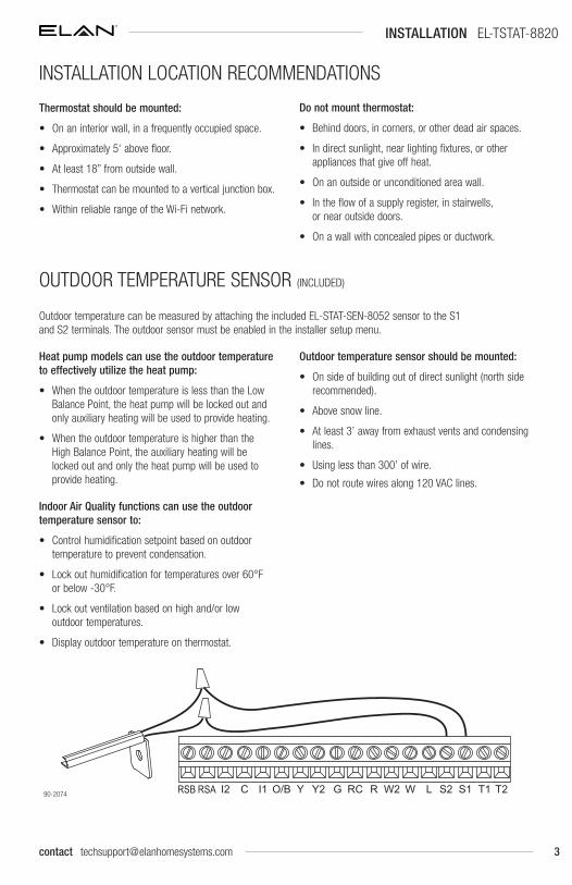
Outdoor temperature can be measured by attaching the included EL-STAT-SEN-8052 sensor to the S1 and S2 terminals. The outdoor sensor must be enabled in the installer setup menu.
Heat pump models can use the outdoor temperature to effectively utilize the heat pump:
• When the outdoor temperature is less than the Low Balance Point, the heat pump will be locked out and only auxiliary heating will be used to provide heating.
• When the outdoor temperature is higher than the High Balance Point, the auxiliary heating will be locked out and only the heat pump will be used to provide heating.
Indoor Air Quality functions can use the outdoor temperature sensor to:
• Control humidification setpoint based on outdoor temperature to prevent condensation.
• Lock out humidification for temperatures over 60°F or below -30°F.
• Lock out ventilation based on high and/or low outdoor temperatures.
• Display outdoor temperature on thermostat.
Outdoor temperature sensor should be mounted:
• On side of building out of direct sunlight (north side recommended).
• Above snow line.
• At least 3’ away from exhaust vents and condensing lines.
• Using less than 300’ of wire.
• Do not route wires along 120 VAC lines.
GY2YO/BI1 WRC R W2 S2LC S1 T1 T2I2RSARSB90-2074
INSTALLATION LOCATION RECOMMENDATIONS
Thermostat should be mounted:
• On an interior wall, in a frequently occupied space.
• Approximately 5‘ above floor.
• At least 18” from outside wall.
• Thermostat can be mounted to a vertical junction box.
• Within reliable range of the Wi-Fi network.
Do not mount thermostat:
• Behind doors, in corners, or other dead air spaces.
• In direct sunlight, near lighting fixtures, or other appliances that give off heat.
• On an outside or unconditioned area wall.
• In the flow of a supply register, in stairwells, or near outside doors.
• On a wall with concealed pipes or ductwork.
OUTDOOR TEMPERATURE SENSOR (INCLUDED)

4 www.elanhomesystems.com
INSTALLATION EL-TSTAT-8820
A remote temperature sensor can be used for control if the thermostat is to be mounted in a concealed location or a remote sensor can be averaged with the thermostat sensor to control a large space. An EL-TSTAT-SEN-8051 remote flush mount temperature sensor or EL-TSTAT-SEN-8083 remote flush mount temperature and humidity sensor can be attached to the T1 and T2 terminals and mounted in a recommended area. The remote sensor must be enabled in the installer setup menu, and once enabled will override or be averaged with the thermostat’s internal temperature sensor, based on the setting.
Do not mount remote sensor:
• Behind doors, in corners or other dead air spaces.
• In direct sunlight, near lighting fixtures, or other appliances that give off heat.
• On an outside or unconditioned area wall.
• In the flow of a supply register, in stairwells, or near outside doors.
• On a wall with concealed pipes or ductwork.
• Near 120 VAC lines.
GY2YO/BI1 WRC R W2 S2LC S1 T1 T2I2RSARSB
Remote temperature sensor should be mounted:
• On an interior wall, in a frequently occupied space.
• Approximately 5‘ above floor.
• At least 18” from outside wall.
• Using less than 300’ of wire.
1. Remove the rear mounting plate from the thermostat.
2. Pull wires through the opening on the back of the rear mounting plate.
3. Position and level the mounting plate of the thermostat on wall and mark the hole locations with a pencil.
4. Drill 1/4” holes and insert supplied anchors (drywall only).
5. Place mounting plate over anchors, insert and tighten screws.
6. Seal wire entry holes to prevent drafts affecting temperature readings.
90-2075
90-2076
REMOTE TEMPERATURE SENSOR (Optional)
THERMOSTAT MOUNTING
5contact [email protected]
INSTALLATION EL-TSTAT-8820
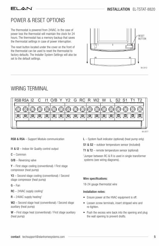
RSB & RSA – Support Module communication
I1 & I2 – Indoor Air Quality control output
C – Common
O/B – Reversing valve
Y – First stage cooling (conventional) / First stage compressor (heat pump)
Y2 – Second stage cooling (conventional) / Second stage compressor (heat pump)
G – Fan
RC – 24VAC supply cooling1
R – 24VAC supply heating1
W2 – Second stage heat (conventional) / Second stage auxiliary (heat pump)
W – First stage heat (conventional) / First stage auxiliary (heat pump)
L – System fault indicator (optional) (heat pump only)
S1 & S2 – outdoor temperature sensor (included)
T1 & T2 – remote temperature sensor (optional)
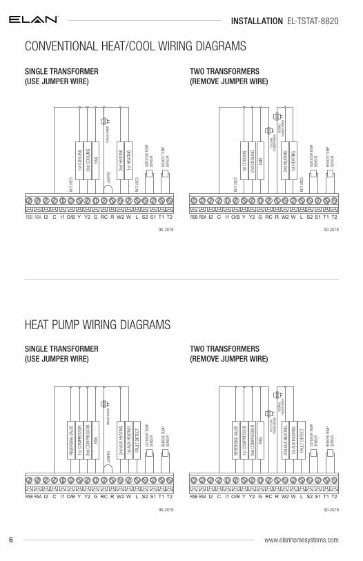
1 Jumper between RC & R is used in single transformer systems (see wiring diagrams).
Wire specifications:
18-24 gauge thermostat wire
Installation notes:
• Ensure power at the HVAC equipment is off.
• Loosen screw terminals, insert stripped wire and re-tighten.
• Push the excess wire back into the opening and plug the wall opening to prevent drafts.
The thermostat is powered from 24VAC. In the case of power loss the thermostat will maintain the clock for 24 hours. The thermostat has a memory backup that saves the thermostat settings in case of power interruption.
The reset button located under the cover on the front of the thermostat can be used to reset the thermostat to factory defaults. The Installer System Settings will also be set to the default settings.
RESETBUTTON
90-2012
GY2YO/BI1 WRC R W2 S2LC S1 T1 T2I2RSARSB
90-2077
WIRING TERMINAL
POWER & RESET OPTIONS
6 www.elanhomesystems.com
SINGLE TRANSFORMER (USE JUMPER WIRE)
TWO TRANSFORMERS (REMOVE JUMPER WIRE)
JUM
PER
OUTD
OOR
TEM
P SE
NSOR
1st H
EATI
NG
1st C
OOLI
NG
FAN
2nd
HEAT
ING
2nd
COOL
ING
NOT
USED
TRAN
SFOR
MER
REM
OTE
TEM
P SE
NSOR
NOT
USED
GY2YO/BI1 WRC R W2 S2LCI2 S1 T1 T2RSB RSA
NOT
USED
2nd
COOL
ING
2nd
HEAT
ING
FAN
1st C
OOLI
NG
1st H
EATI
NG
OUTD
OOR
TEM
P SE
NSOR
COOL
ING
HEAT
ING
REM
OTE
TEM
P SE
NSOR
NOT
USED
TRAN
SFOR
MER TR
ANSF
ORM
ER
GY2YO/BI1 WRC R W2 S2LCI2 S1 T1 T2RSB RSA
SINGLE TRANSFORMER (USE JUMPER WIRE)
TWO TRANSFORMERS (REMOVE JUMPER WIRE)
90-207890-2078
2nd
COM
PRES
SOR
2nd
AUX
HEAT
ING
FAN
1st C
OMPR
ESSO
R
1st A
UX H
EATI
NG
OUTD
OOR
TEM
P SE
NSOR
JUM
PER FA
ULT
DETE
CT
REVE
RSIN
G VA
LVE TR
ANSF
ORM
ER
REM
OTE
TEM
P SE
NSOR
GY2YO/BI1 WRC R W2 S2LCI2 S1 T1 T2RSB RSA
FAUL
T DE
TECT
OUTD
OOR
TEM
P SE
NSOR
1st A
UX H
EATI
NG
1st C
OMPR
ESSO
R
FAN
2nd
AUX
HEAT
ING
2nd
COM
PRES
SOR
TRAN
SFOR
MER
HEAT
PUM
P
HEAT
ING
TRAN
SFOR
MER
REM
OTE
TEM
P SE
NSOR
REVE
RSIN
G VA
LVE
GY2YO/BI1 WRC R W2 S2LCI2 S1 T1 T2RSB RSA
90-207990-2079
INSTALLATION EL-TSTAT-8820
CONVENTIONAL HEAT/COOL WIRING DIAGRAMS
HEAT PUMP WIRING DIAGRAMS

7contact [email protected]
Note: The I1/I2 output is a dry contact closure. The humidifier wiring diagram assumes the control is powering a solenoid valve. The dehumidifier wiring diagram is for a normally open dry contact input. The ventilation diagram assumes the control is for a normally closed damper. Refer to the individual humidifier, dehumidifier or ventilation installation instructions for product specific wiring details.
DEHUMIDIFIER WIRING HUMIDIFIER WIRING
DEHU
MID
IFIE
R
GY2YO/BI1 WRC R W2 S2LCI2 S1 T1 T2RSB RSA
HUM
IDIF
IER
TRAN
SFOR
MER
GY2YO/BI1 WRC R W2 S2LCI2 S1 T1 T2RSB RSA
90-208090-2080
VENTILATION WIRING
NOR
MAL
LY C
LOSE
D DA
MPE
R
TRAN
SFOR
MER
GY2YO/BI1 WRC R W2 S2LCI2 S1 T1 T2RSB RSA
90-2080
INSTALLATION EL-TSTAT-8820
INDOOR AIR QUALITY EQUIPMENT WIRING DIAGRAMS

8 www.elanhomesystems.com
SETUP & TESTING EL-TSTAT-8820
This thermostat has the option of being used in heat pump or heat/cool systems. Switch SW1 located on the back of the thermostat’s face is used to select this option. This setting is displayed in the Installer System Settings under Equipment Type.
HCHP
SW1HEAT/COOL HEAT PUMP
HCHP
EQUIPMENT TYPE SELECTION SWITCH (SW1)
How to enter the installer setup menu AND SELECT EQUIPMENT TO SETUP:
In the Installer Setup menu, Thermostat or Indoor Air Quality (IAQ) setup can be selected. If IAQ setup is selected, the user can then select to set up Air Cleaning, Humidification, Dehumidification or Ventilation.
Press [MODE] to set system to OFF.
Press [MENU] to enter main menu.
Press and hold [SETUP] for seven seconds, [INSTALL SETUP] appears.
Press [INSTALL SETUP] to enter installer setup menu.
Press or to adjust the option.
Press [MENU] to exit.
Press [NEXT] to select option.
Note: If IAQ is selected prior to performing thermostat setup, the Installer System Setting for Outdoor Sensor will be presented prior to entering IAQ setup.
INSTALLER SETUP MENU
Press [NEXT] or [BACK] to page through the settings.
Press or to adjust the setting.
Press [DONE] to save and exit, or [CANCEL] to exit without saving.
The thermostat will discard changes and exit if nothing is pressed within 60 seconds.
To reset the Installer System Settings to the default settings, reset the thermostat by pressing the [RESET] button for 5 seconds.
SETTING NUMBER
SETTING DESCRIPTION
SETTING OPTIONS
CHANGE SYSTEM SETTINGS
9
SETUP & TESTING EL-TSTAT-8820
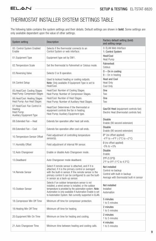
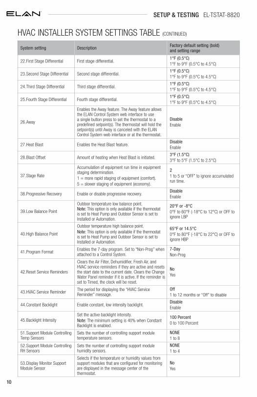
The following table contains the system settings and their details. Default settings are shown in bold. Some settings are only available dependent upon the value of other settings.
System setting Description Factory default setting (bold) and setting range
00. Control System Enabled Enable
Selects if the thermostat connects to an Control System or web interface.
0: ELAN Web Interface1: Control System
01. Equipment Type Equipment type set by SW1.Heat/CoolHeat Pump
02. Temperature Scale Set the thermostat to Fahrenheit or Celsius mode.FahrenheitCelsius
03. Reversing Valve Selects O or B operation.O – On in coolingB – On in heating
04. Control SetupUsed to lockout heating or cooling outputs. Note: Only available if Equipment Type is set to Heat/Cool.
Heat and CoolHeat OnlyCool Only
05. Heat/Cool: Cooling Stages Heat Pump: Compressor Stages
Heat/Cool: Number of Cooling Stages.Heat Pump: Number of Compressor Stages.
One Two
06. Heat/Cool: Heating Stages Heat Pump: Aux Heat Stages
Heat/Cool: Number of Heat Stages.Heat Pump: Number of Auxiliary Heat Stages.
One Two
07. Heat/Cool: Fan Control in Heating Heat Pump: Auxiliary Equipment Type
Heat/Cool: Determines if the thermostat or equipment controls the fan in heating.Heat Pump: Auxiliary Equipment type.
Gas/Oil Heat (equipment controls fan)Electric Heat (thermostat controls fan)
08. Extended Fan – Heat Extends fan operation after heat call ends.DisableEnable (90 second extension)
09. Extended Fan – Cool Extends fan operation after cool call ends.DisableEnable (90 second extension)
10. Temperature Sensor Offset Field adjustment of controlling temperature sensor(s).
0° (no offset applied)-4°F to +4°F (-2°C to +2°C)
11. Humidity Offset Field adjustment of internal RH sensor.0 (no offset applied)-5% to +5%
12. Auto Changeover Enable or disable Auto Changeover mode.DisableEnable
13. Deadband Auto Changeover mode deadband.3°F (1.5°C)2°F to 9°F (1°C to 4.5°C)
14. Remote Sensor
Select if remote sensor is attached, and if it is attached, if it is the primary control or averaged with the built-in sensor. If the remote sensor is the primary control it can be configured to use the built-in sensor as a back-up sensor.
Not installedControl no backupControl with built-in backupAverage with thermostat built-in sensor
15. Outdoor Sensor
Selects if an outdoor temperature sensor is not installed, a wired sensor is installed, or the outdoor temperature is provided by the automation system. Note: Automation is only available if Automation Enable is set to Automation System. Not currently supported in ELAN.
Not installedInstalledAutomation
18. Compressor Min Off Time Minimum off time for compressor protection.5 minutes1 to 5 minutes
19. Heating Min Off Time Minimum off time for heating.2 minutes1 to 5 minutes
20. Equipment Min On Time Minimum on time for heating and cooling.2 minutes1 to 5 minutes
21. Auto Changeover Time Minimum time between heating and cooling calls.4 minutes1 to 5 minutes
THERMOSTAT INSTALLER SYSTEM SETTINGS TABLE
10
System setting Description Factory default setting (bold) and setting range
22. First Stage Differential First stage differential.1°F (0.5°C)1°F to 9°F (0.5°C to 4.5°C)
23. Second Stage Differential Second stage differential.1°F (0.5°C)1°F to 9°F (0.5°C to 4.5°C)
24. Third Stage Differential Third stage differential.1°F (0.5°C)1°F to 9°F (0.5°C to 4.5°C)
25. Fourth Stage Differential Fourth stage differential.1°F (0.5°C)1°F to 9°F (0.5°C to 4.5°C)
26. Away
Enables the Away feature. The Away feature allows the ELAN Control System web interface to use a single button press to set the thermostat to a predefined setpoint(s). The thermostat will hold the setpoint(s) until Away is canceled with the ELAN Control System web interface or at the thermostat.
DisableEnable
27. Heat Blast Enables the Heat Blast feature.DisableEnable
28. Blast Offset Amount of heating when Heat Blast is initiated.3°F (1.5°C)3°F to 5°F (1.5°C to 2.5°C)
37. Stage Rate
Accumulation of equipment run time in equipment staging determination.1 = more rapid staging of equipment (comfort).5 = slower staging of equipment (economy).
21 to 5 or “OFF” to ignore accumulated run time.
38. Progressive Recovery Enable or disable progressive recovery.DisableEnable
39. Low Balance Point
Outdoor temperature low balance point. Note: This option is only available if the thermostat is set to Heat Pump and Outdoor Sensor is set to Installed or Automation.
20°F or -8°C0°F to 60°F (-18°C to 12°C) or OFF to ignore LBP
40. High Balance Point
Outdoor temperature high balance point. Note: This option is only available if the thermostat is set to Heat Pump and Outdoor Sensor is set to Installed or Automation.
65°F or 14.5°C0°F to 80°F (-18°C to 22°C) or OFF to ignore HBP
41. Program Format Enables the 7-day program. Set to “Non-Prog” when attached to a Control System.
7-DayNon-Prog
42. Reset Service Reminders
Clears the Air Filter, Dehumidifier, Fresh Air, and HVAC service reminders if they are active and resets the start date to the current date. Clears the Change Water Panel reminder if it is active. If the reminder is set to Timed, the clock will be reset.
NoYes
43. HVAC Service Reminder The period for displaying the “HVAC Service Reminder” message.
Off1 to 12 months or “Off” to disable
44. Constant Backlight Enable constant, low intensity backlight.DisableEnable
45. Backlight IntensitySet the active backlight intensity.Note: The minimum setting is 40% when Constant Backlight is enabled.
100 Percent0 to 100 Percent
51. Support Module Controlling Temp Sensors
Sets the number of controlling support module temperature sensors.
NONE1 to 8
52. Support Module Controlling RH Sensors
Sets the number of controlling support module humidity sensors.
NONE1 to 4
53. Display Monitor Support Module Sensor
Selects if the temperature or humidity values from support modules that are configured for monitoring are displayed in the message center of the thermostat.
NoYes
SETUP & TESTING EL-TSTAT-8820
HVAC INSTALLER SYSTEM SETTINGS TABLE (CONTINUED)
11contact [email protected]
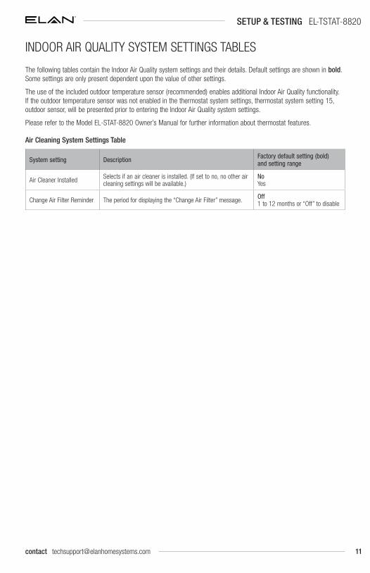
The following tables contain the Indoor Air Quality system settings and their details. Default settings are shown in bold. Some settings are only present dependent upon the value of other settings.
The use of the included outdoor temperature sensor (recommended) enables additional Indoor Air Quality functionality. If the outdoor temperature sensor was not enabled in the thermostat system settings, thermostat system setting 15, outdoor sensor, will be presented prior to entering the Indoor Air Quality system settings.
Please refer to the Model EL-STAT-8820 Owner’s Manual for further information about thermostat features.
Air Cleaning System Settings Table
System setting Description Factory default setting (bold) and setting range
Air Cleaner Installed Selects if an air cleaner is installed. (If set to no, no other air cleaning settings will be available.)
NoYes
Change Air Filter Reminder The period for displaying the “Change Air Filter” message. Off1 to 12 months or “Off” to disable
SETUP & TESTING EL-TSTAT-8820
INDOOR AIR QUALITY SYSTEM SETTINGS TABLES
12 www.elanhomesystems.com
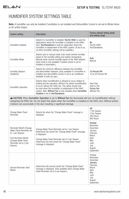
Note: A humidifier can only be installed if ventilation is not installed and Dehumidifier Control is not set to Whole Home or AC w/IAQ Output.
System setting Description Factory default setting (bold) and setting range
Humidifier Installed
Selects if a humidifier is installed. Yes/On HVAC is used for applications where the humidifier is installed on the HVAC duct. Yes/Standalone is used for application where the humidifier is independent of the HVAC system. (If set to no, no other humidifier settings will be available.)
NoYes/On HVACYes/Standalone
Humidifier Mode
Selects auto or manual mode. Auto mode controls humidity based on the humidity setting and outdoor temperature. Manual mode controls humidity based on the %RH setpoint. (Auto mode is only available if outdoor sensor is set to Installed or Automation.)
AutoManual
Humidity Setpoint Deadband
Selects the minimum difference between the humidifier and dehumidifier setpoints. (Only available if a humidifier is installed and dehumidifier control is set to air conditioner. Available in both set-ups.)
10 Percent RH10 to 20 Percent RH
Humidifier Operation
Selects when humidification is allowed to occur relative to heating and fan operation. Without Fan allows humidification to occur without the HVAC fan. This option should only be used when the humidifier is independent of the HVAC system. Note: Without Fan is only available when Humidifier Installed is set to Yes/Standalone.
Heat OnlyHeat or FanForces FanWithout Fan
CAUTION: When Humidifier Operation is set to Without Fan the thermostat will turn on humidification without energizing the HVAC fan. Do not select this option when the humidifier is installed on the HVAC duct. Without airflow moisture can accumulate in the duct resulting in significant damage.
Change Water Panel Reminder
Selects the when the “Change Water Panel” message is displayed.
Off1 Per Season2 Per Season300 Hours600 Hours
Reminder Month (Change Water Panel Reminder set to 1 per Season)
First Reminder Month (Change Water Panel Reminder set to 2 per Season)
Change Water Panel Reminder set to 1 per Season: Determines the month the “Change Water Panel” message is displayed.
Change Water Panel Reminder set to 2 per Season: Determines the first month the “Change Water Panel” message is displayed.
OctoberNovemberDecemberJanuaryFebruaryMarchAprilMayJuneJulyAugustSeptember
Second Reminder Start Month
Determines the second month the “Change Water Panel” message is displayed. (Only available when Change Water Panel Reminder set to 2 per Season.)
OctoberNovemberDecemberJanuaryFebruaryMarchAprilMayJuneJulyAugustSeptember
SETUP & TESTING EL-TSTAT-8820
HUMIDIFIER SYSTEM SETTINGS TABLE
13contact [email protected]
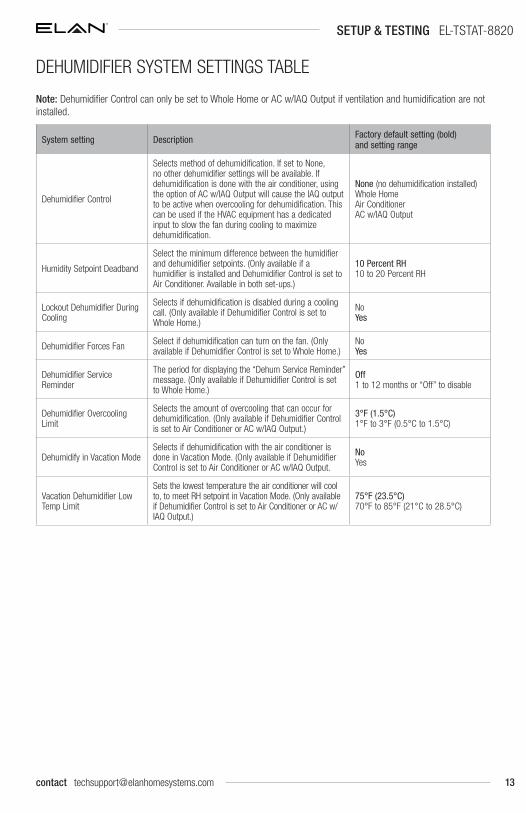
Note: Dehumidifier Control can only be set to Whole Home or AC w/IAQ Output if ventilation and humidification are not installed.
System setting Description Factory default setting (bold) and setting range
Dehumidifier Control
Selects method of dehumidification. If set to None, no other dehumidifier settings will be available. If dehumidification is done with the air conditioner, using the option of AC w/IAQ Output will cause the IAQ output to be active when overcooling for dehumidification. This can be used if the HVAC equipment has a dedicated input to slow the fan during cooling to maximize dehumidification.
None (no dehumidification installed)Whole HomeAir ConditionerAC w/IAQ Output
Humidity Setpoint Deadband
Select the minimum difference between the humidifier and dehumidifier setpoints. (Only available if a humidifier is installed and Dehumidifier Control is set to Air Conditioner. Available in both set-ups.)
10 Percent RH10 to 20 Percent RH
Lockout Dehumidifier During Cooling
Selects if dehumidification is disabled during a cooling call. (Only available if Dehumidifier Control is set to Whole Home.)
NoYes
Dehumidifier Forces Fan Select if dehumidification can turn on the fan. (Only available if Dehumidifier Control is set to Whole Home.)
NoYes
Dehumidifier Service Reminder
The period for displaying the “Dehum Service Reminder” message. (Only available if Dehumidifier Control is set to Whole Home.)
Off1 to 12 months or “Off” to disable
Dehumidifier Overcooling Limit
Selects the amount of overcooling that can occur for dehumidification. (Only available if Dehumidifier Control is set to Air Conditioner or AC w/IAQ Output.)
3°F (1.5°C)1°F to 3°F (0.5°C to 1.5°C)
Dehumidify in Vacation ModeSelects if dehumidification with the air conditioner is done in Vacation Mode. (Only available if Dehumidifier Control is set to Air Conditioner or AC w/IAQ Output.
NoYes
Vacation Dehumidifier Low Temp Limit
Sets the lowest temperature the air conditioner will cool to, to meet RH setpoint in Vacation Mode. (Only available if Dehumidifier Control is set to Air Conditioner or AC w/IAQ Output.)
75°F (23.5°C)70°F to 85°F (21°C to 28.5°C)
SETUP & TESTING EL-TSTAT-8820
DEHUMIDIFIER SYSTEM SETTINGS TABLE

14 www.elanhomesystems.com
Note: Ventilation can only be installed if humidification is not installed and Dehumidifier Control is not set to Whole Home or AC w/IAQ Output.
System setting Description Factory default setting (bold) and setting range
Fresh Air Vent InstalledSelects if ventilation is installed. (If set to No, no other ventilation settings will be available.)
NoYes
Fresh Air Setup Type
Selects if ventilation is configured through the Code setup or Comfort. Comfort setup has more lockout options. Code setting ensures missed lockout time is made up.
ComfortCode
Number of BedroomsSelects the number of bedrooms to be used for the Calculated Minutes per Hour.
3 Bedrooms1 to 10 Bedrooms
Home SizeSelects the size of the home to be used for the Calculated Minutes per Hour.
2500 SQ FT500 to 7500 SQ FT
Measured CFMSelects the ventilation CFM to be used for the Calculated Minutes per Hour.
110 CFM30 to 250 CFM
Calculated Minutes per Hour Displays the Fresh Air Time calculated.NoneRange 6 to 60 Minutes
OverrideManual adjustment of Calculated Minutes per Hour.
(Calculated Minutes per Hour)Range 6 to 60 Minutes
Enable High Vent RH LimitSelects if ventilation is disabled if the indoor RH exceeds the indoor RH limit. (Only available if Fresh Air Setup is set to Comfort.)
YesNo
High Vent RH LimitSets the ventilation indoor RH lockout limit. (Only available if Enable High Vent RH Limit is set to Yes.)
55%45% to 70%
Enable Low Vent RH LimitSelects if ventilation is disabled if the indoor RH exceeds the indoor RH limit. (Only available if Fresh Air Setup is set to Comfort.)
NoYes
Low Vent RH LimitSets the ventilation indoor RH lockout limit. (Only available if Enable Low Vent RH Limit is set to Yes.)
20%10% to 30%
SETUP & TESTING EL-TSTAT-8820
VENTILATION SYSTEM SETTINGS TABLE
15contact [email protected]
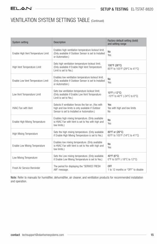
System setting Description Factory default setting (bold) and setting range
Enable High Vent Temperature LimitEnables high ventilation temperature lockout limit. (Only available if Outdoor Sensor is set to Installed or Automation.)
NoYes
High Vent Temperature LimitSets high ventilation temperature lockout limit. (Only available if Enable High Vent Temperature Limit is set to Yes.)
100°F (38°C)85°F to 105°F (29°C to 41°C)
Enable Low Vent Temperature LimitEnables low ventilation temperature lockout limit. (Only available if Outdoor Sensor is set to Installed or Automation.)
NoYes
Low Vent Temperature LimitSets low ventilation temperature lockout limit. (Only available if Enable Low Vent Temperature Limit is set to Yes.)
10°F (-12°C)-10°F to 40°F (-24°C to 6°C)
HVAC Fan with Vent Selects if ventilation forces the fan on. (Yes with high and low limits is only available if Outdoor Sensor is set to Installed or Automation.)
YesYes with high and low limitsNo
Enable High Mixing TemperatureEnables high mixing temperature. (Only available is HVAC Fan with Vent is set to Yes with high and low limits.)
NoYes
High Mixing TemperatureSets the high mixing temperature. (Only available if Enable High Mixing Temperature is set to Yes.)
80°F or (26°C)60°F to 105°F (14°C to 41°C)
Enable Low Mixing TemperatureEnables low mixing temperature. (Only available is HVAC Fan with Vent is set to Yes with high and low limits.)
NoYes
Low Mixing TemperatureSets the Low mixing temperature. (Only available if Enable Low Mixing Temperature is set to Yes.)
40°F (6°C)0°F to 50°F (-18°C to 12°C)
Fresh Air Service ReminderThe period for displaying the “SERVICE FRESH AIR” message.
OFF1 to 12 months or “OFF” to disable
Note: Refer to manuals for humidifier, dehumidifier, air cleaner, and ventilation products for recommended installation and operation.
SETUP & TESTING EL-TSTAT-8820
VENTILATION SYSTEM SETTINGS TABLE (Continued)
16
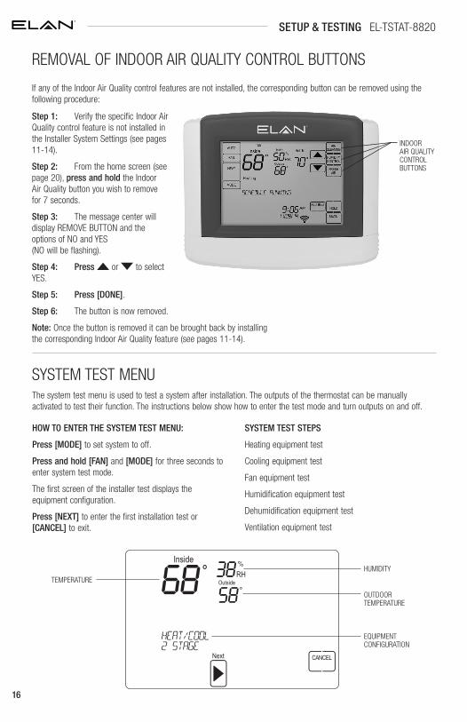
Step 1: Verify the specific Indoor Air Quality control feature is not installed in the Installer System Settings (see pages 11-14).
Step 2: From the home screen (see page 20), press and hold the Indoor Air Quality button you wish to remove for 7 seconds.
Step 3: The message center will display REMOVE BUTTON and the options of NO and YES (NO will be flashing).
Step 4: Press or to select YES.
Step 5: Press [DONE].
Step 6: The button is now removed.
Note: Once the button is removed it can be brought back by installing the corresponding Indoor Air Quality feature (see pages 11-14).
If any of the Indoor Air Quality control features are not installed, the corresponding button can be removed using the following procedure:
INDOOR AIR QUALITY CONTROL BUTTONS
The system test menu is used to test a system after installation. The outputs of the thermostat can be manually activated to test their function. The instructions below show how to enter the test mode and turn outputs on and off.
SYSTEM TEST STEPS
Heating equipment test
Cooling equipment test
Fan equipment test
Humidification equipment test
Dehumidification equipment test
Ventilation equipment test
HOW TO ENTER THE SYSTEM TEST MENU:
Press [MODE] to set system to off.
Press and hold [FAN] and [MODE] for three seconds to enter system test mode.
The first screen of the installer test displays the equipment configuration.
Press [NEXT] to enter the first installation test or [CANCEL] to exit.
TEMPERATURE
HUMIDITY
OUTDOOR TEMPERATURE
EQUIPMENT CONFIGURATION
SETUP & TESTING EL-TSTAT-8820
REMOVAL OF INDOOR AIR QUALITY CONTROL BUTTONS
SYSTEM TEST MENU
17contact [email protected]
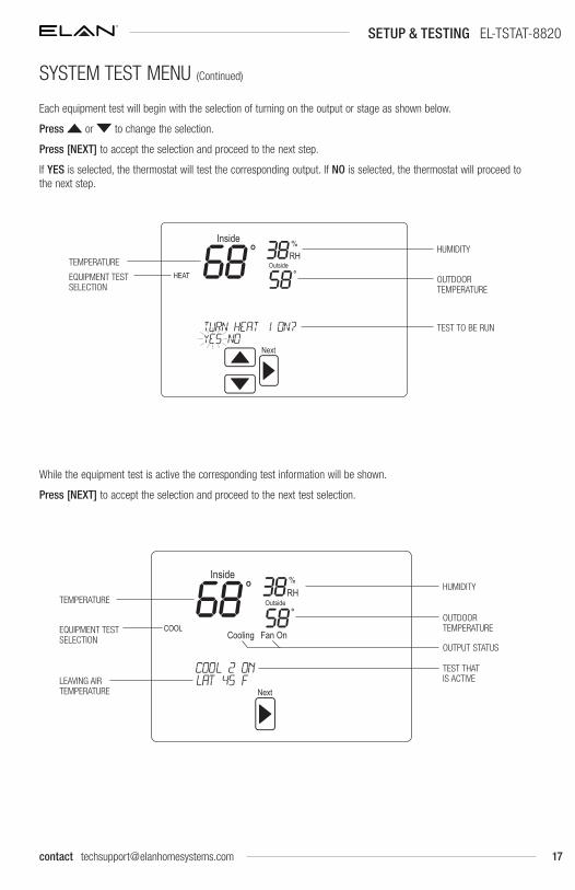
While the equipment test is active the corresponding test information will be shown.
Press [NEXT] to accept the selection and proceed to the next test selection.
Each equipment test will begin with the selection of turning on the output or stage as shown below.
Press or to change the selection.
Press [NEXT] to accept the selection and proceed to the next step.
If YES is selected, the thermostat will test the corresponding output. If NO is selected, the thermostat will proceed to the next step.
TEMPERATURE
EQUIPMENT TEST SELECTION
HUMIDITY
OUTDOOR TEMPERATURE
TEST TO BE RUN
TEMPERATURE
LEAVING AIR TEMPERATURE
EQUIPMENT TEST SELECTION
HUMIDITY
OUTDOOR TEMPERATURE
OUTPUT STATUS
TEST THAT IS ACTIVE
SETUP & TESTING EL-TSTAT-8820
SYSTEM TEST MENU (Continued)

18
HEAT / COOL HEATING EQUIPMENT TESTHeat Type W W2 Y Y2 G
Gas 1st Stage Test ON
Gas 2nd Stage Test ON ON
Electric 1st Stage Test ON ON
Electric 2nd Stage Test ON ON ON
HEAT PUMP HEATING EQUIPMENT TEST (ELECTRIC HEAT)
Compressor Stages
Aux Stages W W2 Y Y2
O/B set to
GO B
1 1 1st Stage Test ON ON ON
1 1 2nd Stage Test ON ON ON ON
2 1 1st Stage Test ON ON ON
2 1 2nd Stage Test ON ON ON ON
2 1 3rd Stage Test ON ON ON ON ON
1 2 1st Stage Test ON ON ON
1 2 2nd Stage Test ON ON ON ON
1 2 3rd Stage Test ON ON ON ON ON
2 2 1st Stage Test ON ON ON
2 2 2nd Stage Test ON ON ON ON
2 2 3rd Stage Test ON ON ON ON ON
2 2 4th Stage Test ON ON ON ON ON ON
Note: System Variable 03, O/B operation selects O or B.
HEAT PUMP HEATING EQUIPMENT TEST (GAS HEAT)
Compressor Stages
Aux Stages W W2 Y Y2
O/B set to
GO B
1 1 1st Stage Test ON ON ON
1 1 2nd Stage Test ON ON
2 1 1st Stage Test ON ON ON
2 1 2nd Stage Test ON ON ON ON
2 1 3rd Stage Test ON ON
1 2 1st Stage Test ON ON ON
1 2 2nd Stage Test ON ON
1 2 3rd Stage Test ON ON ON
2 2 1st Stage Test ON ON ON
2 2 2nd Stage Test ON ON ON ON
2 2 3rd Stage Test ON ON
2 2 4th Stage Test ON ON ON
Note: System Variable 03, O/B operation selects O or B.
SETUP & TESTING EL-TSTAT-8820
SYSTEM TEST TABLES
19contact [email protected]
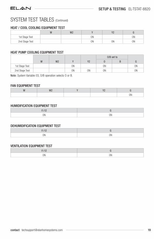
HEAT / COOL COOLING EQUIPMENT TESTW W2 Y Y2 G
1st Stage Test ON ON
2nd Stage Test ON ON ON
HEAT PUMP COOLING EQUIPMENT TEST
W W2 Y Y2
O/B set to
GO B
1st Stage Test ON ON ON
2nd Stage Test ON ON ON ON
Note: System Variable 03, O/B operation selects O or B.
FAN EQUIPMENT TESTW W2 Y Y2 G
ON
HUMIDIFICATION EQUIPMENT TESTI1/ I2 G
ON ON
DEHUMIDIFICATION EQUIPMENT TESTI1/ I2 G
ON ON
VENTILATION EQUIPMENT TESTI1/ I2 G
ON ON
SETUP & TESTING EL-TSTAT-8820
SYSTEM TEST TABLES (Continued)
20 www.elanhomesystems.com
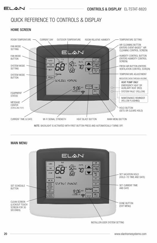
CONTROLS & DISPLAY EL-TSTAT-8820
NOTE: BACKLIGHT IS ACTIVATED WITH FIRST BUTTON PRESS AND AUTOMATICALLY TURNS OFF.
FAN MODE BUTTON
FAN MODE SETTING
SYSTEM MODE BUTTON
SYSTEM MODE SETTING
WI-FI SIGNAL STRENGTHCURRENT TIME & DATE MAIN MENU BUTTONHEAT BLAST BUTTON
TEMPERATURE ADJUSTMENT
AIR CLEANING BUTTON (ENTERS EVENT-BASED™ AIR CLEANING CONTROL SCREEN)
HUMIDITY CONTROL BUTTON (ENTERS HUMIDITY CONTROL SCREEN)
FRESH AIR BUTTON (ENTERS VENTILATION CONTROL SCREEN)
HOLD BUTTON (SETS OR CLEARS HOLD)
HEAT PUMP ONLYEMERGENCY HEAT OR AUXILIARY HEAT (RED)SYSTEM FAULT (YELLOW)
MAINTENANCE REMINDER (YELLOW FLASHING)
INDICATORS SHOW THROUGH HOUSING
EQUIPMENT STATUS
MESSAGE CENTER (SCROLLING TEXT)
ROOM TEMPERATURE CURRENT DAY TEMPERATURE SETTINGOUTDOOR TEMPERATURE ROOM RELATIVE HUMIDITY
SET SCHEDULE BUTTON
INSTALLER/USER SYSTEM SETTING
CLEAN SCREEN (LOCKOUT TOUCH SCREEN FOR 30 SECONDS)
SET VACATION HOLD (HOLD–TO TIME AND DATE)
SET CURRENT TIME AND DATE
DONE BUTTON (EXIT MENU)
QUICK REFERENCE TO CONTROLS & DISPLAY
HOME SCREEN
MAIN MENU

21contact [email protected]
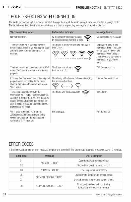
TROUBLESHOOTING EL-TSTAT-8820
TROUBLESHOOTING
DISPLAY IS BLANK
• Check circuit breaker and reset if necessary.
• Make sure power switch at heating & cooling system is on.
• Make sure furnace door is closed securely.
TEMPERATURE SETTINGS DO NOT CHANGE
Make sure heating and cooling temperatures are set to acceptable ranges:
• Heat: 40° to 90°F (4° to 32°C).
• Cool: 50° to 99°F (10° to 37°C).
HEATING SYSTEM DOES NOT RESPOND (“HEATING” APPEARS ON SCREEN)
• Check for 24VAC at the equipment on the secondary side of the transformer between power and common. If voltage is not present, check the heating equipment to find the cause of the problem.
• Check for 24VAC between the heat terminal (W) and the transformer common. If 24VAC is present, the thermostat is functional. Check the heating equipment to find the cause of the problem.
• Check for loose or broken wires between the thermostat and the heating equipment.
COOLING SYSTEM DOES NOT RESPOND (“COOLING” APPEARS ON SCREEN)
• Check for 24VAC at the equipment on the secondary side of the transformer between power and common. If voltage is not present, check the cooling equipment to find the cause of the problem.
• Check for 24VAC between the cooling terminal (Y) and the transformer common. If 24VAC is present, the thermostat is functional. Check the cooling system to find the cause of the problem.
• Check for loose or broken wires between the thermostat and the cooling equipment.
FAN DOES NOT TURN ON IN A CALL FOR HEAT
• Check System Setting 07 (Fan Control), to make sure the fan control is properly set to match the type of system (see page 9).
HEAT PUMP ISSUES COOL AIR IN HEAT MODE, OR WARM AIR IN COOL MODE
• Check System Setting 03 (O/B Operation) to make sure the reversing valve operation matches the heat pump.
HEAT/COOL BOTH ON AT SAME TIME
• Check SW1 (Equipment Type), to make sure it is set to match the installed heating/cooling equipment (see page 8).
• Check to make sure heating and cooling wires are not shorted together.
HEATING EQUIPMENT IS RUNNING IN COOL MODE
• Check SW1 (Equipment Type), to make sure it is set to match the installed heating/cooling equipment (see page 8).
“HEATING” IS NOT DISPLAYED
• Check Installer System Setting number 04 (Control Setup) is set correctly.
• Change the System Mode to Heat, and set the temperature level above the current room temperature.
“COOLING” IS NOT DISPLAYED
• Check Installer System Setting number 04 (Control Setup) is set correctly.
• Change the System Mode to Cool, and set the temperature level below the current room temperature.
HUMIDIFIER DOES NOT OPERATE IN AUTO MODE
• Check Installer System Setting number 15 (Outdoor Sensor) is set to Installed or Automation.
• Verify that the outdoor sensor is functioning correctly or if it is set to Automation that it has not timed out. If the sensor is functioning correctly the outdoor temperature will display in the outdoor temperature location (see Home Screen on page 20 for the location).
22
TROUBLESHOOTING EL-TSTAT-8820
Wi-Fi connection status Radio status indicator Message Center
Normal Operation. Wi-Fi signal strength is indicated by the appropriate number of bars.
No corresponding message
The thermostat Wi-Fi settings have not been entered. Refer to Wi-Fi Setup on page 2 for instructions for entering the Wi-Fi settings.
The frame is displayed and the bars cycle from 0 to 4.
Displays the SSID of the thermostat. Note: The SSID will be used to identify the thermostat when using a smart device to connect the thermostat to your Wi-Fi router.
The thermostat cannot connect to the Wi-Fi router. Verify that the router is functioning properly.
The frame and all bars flash on and off.
WiFi Connection Lost
Indicates the thermostat was not configured properly when connecting to the router. Confirm there is no IP conflict and repeat Wi-Fi setup.
The display will alternate between displaying the frame and all bars.
Internet Connection Lost
There is an internal error with the thermostat Wi-Fi radio. The thermostat will continue to control the HVAC and indoor air quality control equipment, but will not be able to connect to Wi-Fi. Contact an HVAC professional for repair.
The frame will flash on and off. Radio Error
Wi-Fi radio turned off. Refer to the Accessingg Wi-Fi Settings Menu in the Owner’s Manual for information about turning the Wi-Fi radio on.
Not displayed. WiFi Turned Off
If the thermostat enters an error mode, all outputs are turned off. The thermostat attempts to recover every 10 minutes.
Error code Message Error Description
01 “SENSOR ERROR”
Open temperature sensor circuit
02 Shorted temperature sensor circuit
03 “EEPROM ERROR” Error in permanent memory
06“REMOTE SENSOR ERROR”
Open remote temperature sensor circuit
07 Shorted remote temperature sensor circuit
08 “SUPPORT MODULES LOST”All support modules with controlling
temperature sensors are in error
The Wi-Fi connection status is communicated through the use of the radio strength indicator and the message center. The table below describes the various statuses and the corresponding message and radio bar display.
TROUBLESHOOTING WI-FI CONNECTION
ERROR CODES
www.elanhomesystems.com
23
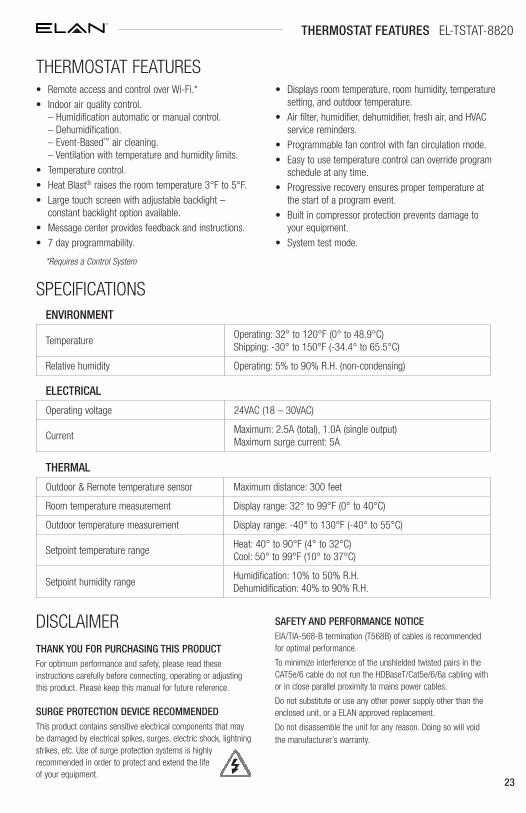
THERMOSTAT FEATURES EL-TSTAT-8820
• Remote access and control over Wi-Fi.*• Indoor air quality control.
– Humidification automatic or manual control. – Dehumidification. – Event-Based™ air cleaning. – Ventilation with temperature and humidity limits.
• Temperature control.• Heat Blast® raises the room temperature 3°F to 5°F.• Large touch screen with adjustable backlight –
constant backlight option available.• Message center provides feedback and instructions.• 7 day programmability.
• Displays room temperature, room humidity, temperature setting, and outdoor temperature.
• Air filter, humidifier, dehumidifier, fresh air, and HVAC service reminders.
• Programmable fan control with fan circulation mode.• Easy to use temperature control can override program
schedule at any time.• Progressive recovery ensures proper temperature at
the start of a program event.• Built in compressor protection prevents damage to
your equipment.• System test mode.
THERMAL
Outdoor & Remote temperature sensor Maximum distance: 300 feet
Room temperature measurement Display range: 32° to 99°F (0° to 40°C)
Outdoor temperature measurement Display range: -40° to 130°F (-40° to 55°C)
Setpoint temperature rangeHeat: 40° to 90°F (4° to 32°C) Cool: 50° to 99°F (10° to 37°C)
Setpoint humidity rangeHumidification: 10% to 50% R.H. Dehumidification: 40% to 90% R.H.
ELECTRICAL
Operating voltage 24VAC (18 – 30VAC)
CurrentMaximum: 2.5A (total), 1.0A (single output) Maximum surge current: 5A
ENVIRONMENT
TemperatureOperating: 32° to 120°F (0° to 48.9°C) Shipping: -30° to 150°F (-34.4° to 65.5°C)
Relative humidity Operating: 5% to 90% R.H. (non-condensing)
SPECIFICATIONS
THERMOSTAT FEATURES
DISCLAIMERTHANK YOU FOR PURCHASING THIS PRODUCTFor optimum performance and safety, please read these instructions carefully before connecting, operating or adjusting this product. Please keep this manual for future reference.
SURGE PROTECTION DEVICE RECOMMENDEDThis product contains sensitive electrical components that may be damaged by electrical spikes, surges, electric shock, lightning strikes, etc. Use of surge protection systems is highly recommended in order to protect and extend the life of your equipment.
SAFETY AND PERFORMANCE NOTICEEIA/TIA-568-B termination (T568B) of cables is recommended for optimal performance.
To minimize interference of the unshielded twisted pairs in the CAT5e/6 cable do not run the HDBaseT/Cat5e/6/6a cabling with or in close parallel proximity to mains power cables.
Do not substitute or use any other power supply other than the enclosed unit, or a ELAN approved replacement.
Do not disassemble the unit for any reason. Doing so will void the manufacturer’s warranty.
*Requires a Control System

10018971 Rev-A0, 10/2017
main:1 (800) 472-5555 - US1 (707) 283-5900 - International1 (707) 283-5901 - Fax
tech support:[email protected]
web:elanhomesystems.com
© 2017 ELAN® is a registered trademark of Core Brands, LLC.