elastic multi body simulation of a multi-cylinder engine · ... fem, gasoline engine dynamics,...
TRANSCRIPT

Send Orders for Reprints to [email protected]
The Open Mechanical Engineering Journal, 2014, 8, 157-169 157
1874-155X/14 2014 Bentham Open
Open Access
Elastic Multi Body Simulation of a Multi-Cylinder Engine D. Siano*,1 and R. Citarella2
1Istituto Motori, CNR, Naples, Italy 1University of Salerno, Department of Industrial Engineering, Via Giovanni Paolo II, 132, 84084 Fisciano (SA), Itlay
Abstract: This paper analyzes the vibration behavior of an in-line 4-cylinder, 4-strokes, internal combustion turbocharged direct injection gasoline engine. A detailed multi-body numerical model of the engine prototype was used to characterize the whole engine dynamic behavior, in terms of forces and velocities. The crank train multi-body model was created starting from engine geometrical data, and the available combustion loads were employed for the Multi-Body Dynamic Simulation (MBDS). A combined usage of FEM and multi body methodologies were adopted for the dynamic analysis: both crankshaft and cylinder block were considered as flexible bodies, whereas all the other components were considered as rigid. The engine mounts were considered as flexible elements with given stiffness and damping. The hydrodynamic bearings were also modelling. The software LMS Virtual Lab (modules PDS and Motion) and ANSYS were used for the simulation.
Keywords: FEM, gasoline engine dynamics, multi body, vibration,
1. INTRODUCTION
Structural and acoustic modelling methods, used to predict the performance in terms of noise and vibration, have become the key tools in the design process [1-4]. The engine dynamics is explored especially in the low frequency range and at low engine speeds, where the direct vibration transmission by the engine mounts is a critical excitation mechanism [5]. This paper analyses the vibration behavior of an in-line 4-cylinder, 4-strokes, internal combustion turbocharged gasoline engine. A multi-body numerical model of the engine prototype was used to characterize the whole engine dynamic behavior, in terms of forces and velocities. The crank train multi-body model was created starting from engine geometrical data, and the available combustion loads were employed for the Multi-Body Dynamic Simulation (MBDS), with both mechanical and combustion forces acting simultaneously on the engine block.
2. PROBLEM DESCRIPTION AND CAD MODEL
The crank train multi-body model of the engine under testing was created first, using the CAD software CATIA, to build up and then simplify the original CAD models (Fig. 1a, b), which were subsequently exported to ANSYS software by means of the IGES (Initial Graphics Exchange Specification) translation format (the selected “Curve and surface type” was the “B-Spline”). Then, the LMS software [6] Powertrain Dynamic Simulator (PDS) and Motion were used for the model setup and dynamic simulation, respectively. A combined usage of FEM and Multi-Body
*Address correspondence to this author at the Istituto Motori - CNR - Naples, Italy; Tel: +39-0817177108; Fax: +39-081.2396097; E-mail: [email protected]
methodologies were adopted for the engine dynamic analysis [5, 7, 8] (Fig. 2). Since an internal combustion engine represents a complex system, which includes crankshaft, block, piston, flywheel, etc., it was modelling as a multi-body structure. In order to better approximate the real engine behavior both crankshaft and cylinder block were modelling as flexible bodies, whereas all the other components (flywheel, pistons and their connecting rods) were considered as rigid. In Motion module the 3D virtual crank train model, created using the PDS module Crank train, was animated as a multi-body model, in which the mechanical component dynamics were taken into account to better understand the kinematics of the system. In particular, the Motion model was solved considering a number of cycles per minute equal to 1000 rpm (the aim here is to just show the procedure). The engine under test is assembled with pitch and roll angle equal to 12 and 0 degrees respectively; the cylinder pitch is equal to 90 mm. The engine characteristics are summarised in Table 1. To obtain a detailed multi-body model which could describe all crankshaft body contacts (piston-liner, shaft-bearing, etc.), information about all engine components in terms of geometrical data and physical properties (like masses and moments of inertia) were requested. A virtual prototype of the engine under test was modelling using PDS, a software application that provides an intuitive and efficient environment to create virtual prototypes of powertrain systems and subsystems. In particular, the crank train multi-body model of the engine includes (Fig. 3): the crankshaft, the flywheel(considered as a separate component clamped to the crankshaft by a specific joint), the four pistons and their connecting rods. The crankshaft and the block are made of steel (n=0.3, E= 210000 MPa, r=7850 kg/m3) and cast iron GH 190 B (n=0.27, E= 105000 MPa, r=7200 kg/m3), respectively.

158 The Open Mechanical Engineering Journal, 2014, Volume 8 Siano and Citarella
Fig. (1a). Original (left) and simplified (right) block CAD model.
Fig. (1b). Crank shaft CAD model.
Fig. (2). Scheme of the hybrid FEM-multibody approach.

Elastic Multi Body Simulation of a Multi-Cylinder Engine The Open Mechanical Engineering Journal, 2014, Volume 8 159 Table 1. Main engine characteristics.
Displaced volume 1740 cc
Stroke 80.5 mm
Bore 83.0 mm
Connecting Rod 148.0 mm
Number of Cylinders 4
Type 4-stroke
Firing Order 1-3-4-2
The engine mounts (Fig. 4) were considered as flexible elements and characterized in terms of translational (Fig. 5) and rotational (k=2000 Nmm/deg and µ=0.1) stiffness and damping [9]. The hydrodynamic bearings were also modelling, using the theoretical approach implemented in the software [6].
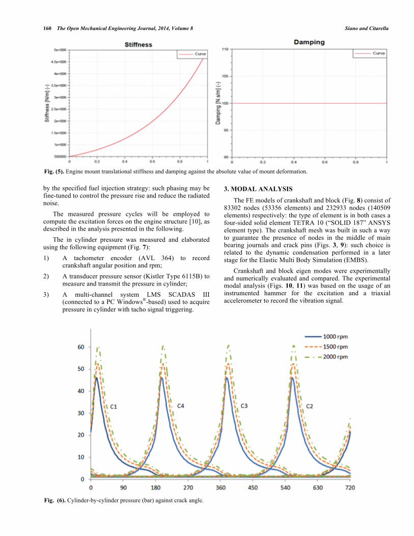
Rigid elements were used in order to maintain unchanged the element relative positions in some regions, for example along piston slides, at main bearing locations (when the hydrodynamic bearings were not explicitly modelling) and at mount locations. Cycle by cycle in cylinder pressure at different engine speeds (1000, 1500, 2000 rpm) under full load conditions, is depicted in Fig. (6). These operating conditions were chosen as excitation force because considered critical in terms of radiated noise. By increasing the rotational speed the burning process advances, the cycle period reduces, and the peak values become higher and higher due to the increased boost level at higher engine speeds. The pressure behavior is considered identical in each cylinder even if small cylinder-by-cylinder variations of the maximum pressure can be observed at the highest speed, depending on the actual filling conditions during the intake stroke. The location of the peak pressure depends indeed on the variable combustion phasing realized
Fig. (3). Cranktrain multi-body model of the 4-cyliner engine with highlight of master nodes for dynamic condensation.
Fig. (4). Engine mounts adopted for the laboratory experimental arrangement.
160 The Open Mechanical Engineering Journal, 2014, Volume 8 Siano and Citarella
by the specified fuel injection strategy: such phasing may be fine-tuned to control the pressure rise and reduce the radiated noise. The measured pressure cycles will be employed to compute the excitation forces on the engine structure [10], as described in the analysis presented in the following. The in cylinder pressure was measured and elaborated using the following equipment (Fig. 7): 1) A tachometer encoder (AVL 364) to record
crankshaft angular position and rpm; 2) A transducer pressure sensor (Kistler Type 6115B) to
measure and transmit the pressure in cylinder; 3) A multi-channel system LMS SCADAS III
(connected to a PC Windows®-based) used to acquire pressure in cylinder with tacho signal triggering.
3. MODAL ANALYSIS
The FE models of crankshaft and block (Fig. 8) consist of 83302 nodes (53356 elements) and 232933 nodes (140509 elements) respectively: the type of element is in both cases a four-sided solid element TETRA 10 (“SOLID 187” ANSYS element type). The crankshaft mesh was built in such a way to guarantee the presence of nodes in the middle of main bearing journals and crack pins (Figs. 3, 9): such choice is related to the dynamic condensation performed in a later stage for the Elastic Multi Body Simulation (EMBS). Crankshaft and block eigen modes were experimentally and numerically evaluated and compared. The experimental modal analysis (Figs. 10, 11) was based on the usage of an instrumented hammer for the excitation and a triaxial accelerometer to record the vibration signal.
Fig. (5). Engine mount translational stiffness and damping against the absolute value of mount deformation.
Fig. (6). Cylinder-by-cylinder pressure (bar) against crack angle.

Elastic Multi Body Simulation of a Multi-Cylinder Engine The Open Mechanical Engineering Journal, 2014, Volume 8 161
The numerical modal analysis was performed with the commercial code ANSYS® 11.0, selecting the PCG (Preconditioned Conjugate Gradient) Lanczos method, obtaining the crankshaft and the block modal parameters, such as natural frequencies (Tables 2 and 3) and numerical mode shapes (Figs. 12a-b, 13a-c).
With reference to Table 2 it is possible to observe the satisfactory correspondence between numerical and experimental outcomes except for the missing 4th and 6th experimental eigen frequencies: this is likely to be a consequence of an accelerometer misplacement (it is unable to detect a given eigen mode e.g. when placed in a nodal
a b c
Fig. (7). Angle Encoder AVL 364 (a), equipped plug Kistler Type 6115B (b) and acquisition system LMS SCADAS III (c).
Fig. (8). Crankshaft (left) and block (right) Finite Element models.
Fig. (9). Crankshaft (left) and block (right) experimental test models.

162 The Open Mechanical Engineering Journal, 2014, Volume 8 Siano and Citarella
point). Moreover, considering that the crankshaft bending eigen modes are evaluated in a free-free configuration (Fig. 10) and consequently significantly underestimate the constrained eigenmodes (those obtained with allowance for
the presence of bearing supports), it is possible to assess that such bending modes are not triggered by the most relevant engine orders.
Fig. (10). Crankshaft experimental set-up for modal analysis with highlight of triaxial accelerometer.
Fig. (11). Block experimental set-up for the modal analysis.
Table 2. Crankshaft modal parameters.
Crankshaft Mode Numerical Eigen Frequency [Hz] Experimental Eigen Frequency [Hz] Relative Error [%]
1- bending (xz plane -1 half-wave) 348.7 350.2 0.43
2- bending (xy plane-1 half-wave) 511.8 497.4 2.82
3- bending (xz plane -2 half-waves) 789.4 817.3 3.54
4- torsional 890.1 --- ---
5- bending (xz plane -3 half-waves) 918.3 959.8 4.52
6- bending (xz plane -4 half-waves) 1204 --- ---
7- bending (xy plane -2 half-waves) 1290 1285 0.38
8 - bending (xy plane -3 half-waves) and locally torsional (around x axis) 1576 1662 5.43

Elastic Multi Body Simulation of a Multi-Cylinder Engine The Open Mechanical Engineering Journal, 2014, Volume 8 163
With reference to Table 3 it is possible to observe a non negligible discrepancy between numerical and experimental natural frequencies with reference to the initial block modal shapes, due to the geometrical modifications on the block model (Fig. 1) and due to the lack of block suspension by low stiffness wires during the experimental test (Fig. 11): in particular the numerical frequencies turn out to be higher than experimental due to the block stiffening produced by the hole filling in the numerical model. Again the problem of missing eigen frequencies appears. From Fig. (14), it is possible to see that the first torsional crankshaft eigen mode at 890.1 Hz is not triggered by the most relevant even engine orders (the 2nd, the 4th and the 6th).
FORCED ANALYSIS RESULTS
The elastic multi body approach for the engine dynamic assessment is illustrated in Fig. (15). FE models of crankshaft and block were used to calculate the related Craig-Bampton modes adopted by the LMS Motion module for the dynamic condensation [11] (the points selected for the dynamic condensation were depicted in orange in Fig. 3). As an example, Figs. (16, 17) show, at 1000 rpm, the color bar plot of the Modal Participation Factors (MPFs) against frequency related to the first six modes of crankshaft and cylinder block respectively. It is possible to observe that at this engine speed (1000 rpm), the most important crankshaft and block mode shape contributions were found
Table 3. Block modal parameters.
Block Mode Numerical Eigen Frequency [Hz] Experimental Eigen Frequency [Hz] Relative Error [%]
1 - torsional (around y axis) 738 --- ---
2 - bending (xy plane, 1 half-wave) 1218 1080 12.8
3 - bending (xz plane) 1486 1335 11.3
4 - bending (xy plane, 2 half-waves) 1800 1682 7.0
5 - bending (xy plane) 2020 1872 7.9
6 - bending (xz plane) 2039 1992 2.4
7 - bending 2092 --- ---
8 - bending (yz plane, 1 half-wave) 2203 --- ---
Fig. (12a). First bending eigen mode (350 Hz): numerical (left) and experimental (right) mode shapes.
Fig. (12b). Third bending (789.4 Hz - left) and fourth torsional (890 Hz - right) crankshaft eigen modes.

164 The Open Mechanical Engineering Journal, 2014, Volume 8 Siano and Citarella
Fig. (13a). First block torsional (around y axis) eigen mode at 738 Hz.
Fig. (13b). Fourth block eigenmode at 1800 Hz (top and bottom view)
Fig. (13c). Fifth block eigen mode at 2020 Hz (top and bottom view).

Elastic Multi Body Simulation of a Multi-Cylinder Engine The Open Mechanical Engineering Journal, 2014, Volume 8 165
in the frequency range 0-100 Hz (first, third and fourth mode) and 0-200 Hz (first, second and sixth mode) respectively. The very low scale values on the right in Figs. (16, 17) describe a vibration phenomenon that, at 1000 rpm, is just moderately influenced by the crankshaft and block flexibility, but, increasing the engine speed (rpm) the importance of allowing for their flexibility gets higher and higher. An experimental campaign by using a Laser Scanning Vibrometer (Polytec) is performed in order to carry out surface vibration measurements restricted to five external block points (Fig. 18).
The experimental velocities in such points (Fig. 19) were compared with the numerical ones (Fig. 20) getting a qualitative consistency (the two scales in Figs. (19, 20) differ by one order of magnitude): a quantitative comparison is still prevented if we consider the relevant simplifications that were still present in the numerical model, which, for example, allow for the cylinder head and for all the remaining upper parts (Fig. 21) by just adding a concentrated mass equal to 490 N with no allowance for the stiffness contribution of such parts. Anyway the expected vibration peaks in correspondence of the even engine orders is correctly forecasted by the numerical analyses whereas the
Fig. (14). Chart highlighting the distance between the first torsional eigen mode and the most relevant even engine orders.
Fig. (15). FEM-Multibody approach for the engine dynamic assessment.
890.091000
1500
2000
2500
3000
3500
4000
4500
5000
5500
6000
0 200 400 600 800 1000
Rpm
[rev
/min
]
Frequency [Hz]
Even engine orders (2, 4, 6)
Multibody system with rigid components
Introduction of flexible models and Craig-Bampton modes
Multibody system with flexible components
EMBS

166 The Open Mechanical Engineering Journal, 2014, Volume 8 Siano and Citarella
Fig. (16). Colorbar plot of the first six crankshaft MPFs vs frequency at 1000 rpm.
Fig. (17). Colorbar plot of the first six cylinder block MPFs vs Frequency, at 1000 rpm.

Elastic Multi Body Simulation of a Multi-Cylinder Engine The Open Mechanical Engineering Journal, 2014, Volume 8 167
lack of peaks at the odd engine orders, in comparison with the experimental outcomes, can be explained by the lack of many important component in the model (Fig. 21) that should be added to progressively improve the simulation accuracy.
CONCLUSION
In the present work a predictive vibration analysis was conducted on a 4-stroke, inline 4-cylinder turbocharged gasoline engine, showing for sake of simplicity only the results related to the engine speed of 1000 rpm.
Fig. (18). Experimental set-up of tested engine with highlight of the five measuring points.
Fig. (19). Experimental velocity spectrum (m/s) against frequency (Hz) in the five considered points.

168 The Open Mechanical Engineering Journal, 2014, Volume 8 Siano and Citarella
Starting from the engine geometrical data, mass and moment of inertia and having measured the in-cylinder pressure curves, the engine vibration behavior was predicted and the crankshaft and cylinder block Modal Participation Factors were computed and analysed. Thanks to the Multi-Body approach, the dynamics of the engine crank train was described taking into account both the
effects of combustion and of inertia forces. Moreover to assess a realistic engine operating behavior, both the crank and the block were considered as flexible bodies. Considering the numerous simplifications in the modelling, an encouraging qualitative agreement between numerical and experimental outcomes is obtained, but, for a quantitative assessment the cylinder head, crack case and oil
Fig. (20). Numerical velocity spectrum (m/s) against frequency (Hz) in the five considered points.
Fig. (21). Highlight of all the powertrain components not explicitly modelling.

Elastic Multi Body Simulation of a Multi-Cylinder Engine The Open Mechanical Engineering Journal, 2014, Volume 8 169 pan are to be added to the considered model (this is the object of current work) because of their non negligible stiffness and inertia impact on the crank train dynamic performance at low frequencies. The dynamics of the engine powertrain and the engine block vibro-acoustic behavior are assessed using LMS Virtual. Lab tools and the FEM commercial code ANSYS.
FUTURE DEVELOPMENTS
Such kind of analysis is needed in order to assess the engine radiated noise (at e.g. 1 meter from the engine vibrating surface according to the standard ISO 3744). With such approach, the influence of each engine resonance on the acoustic behavior, for each tested engine speed, can be analysed. Further activities will concern the engine design optimization in two possible different ways. In the first, in order to decrease the engine vibrations and the radiated noise levels, different engine mounts configurations will be considered. Secondly, a new fuel injection strategy will be analysed. In this latter case, of course, a compromise between engine performance and radiated noise has to be realized. Finally, the effective interior noise reduction in a car vehicle oriented to the passenger comfortwill be verified [12-13].
CONFLICT OF INTEREST
The authors confirm that this article content has no conflict of interest.
ACKNOWLEDGEMENTS
Declared none.
REFERENCES [1] R. Citarella, and D. Siano, “Transmission loss assessment of an air
induction system by BEM” In: Proc. ICAD2006, The 4th
International Conference on Axiomatic Design, Florence, Italy, 2006.
[2] R. Citarella, and M. Landi, “Acoustic analysis of an exhaust manifold by Indirect Boundary Element Method”, Open Mech. Eng. J., vol. 5, pp. 138-151, 2011.
[3] R. Citarella, L. Federico, and A. Cicatiello, “Modal acoustic transfer vector approach in a FEM-BEM vibro-acoustic analysis”, Eng. Anal. Bound. Elem., vol. 31, pp. 248-258, 2007.
[4] E. Armentani, D. De Stefanis, R. Esposito, M. Martorelli, and A. Parente, “Valve cover's numerical vibro-acoustic analysis and experimental correlation”, In: The 6th International Styrian Noise, Vibration & Harshness Congress - Sustainable NVH solutions inspired by ecology and economy, Graz, Austria, 2010.
[5] D. Siano, S. Giacobbe, and F. Bozza, “Noise prediction of a multi-cylinder engine prototype using multi-body dynamic simulation” In: Proc. 10th International Conference on Engines & Vehicles - ICE 2011, Napoli (Italy) 2011, SAE Technical Paper 2011-24-0216.
[6] LMS Virtual. Lab Power Train Dynamic Simulator - LMS International.
[7] E. Armentani, I. Cascella, G. Fioretto, G. Imparato, and M. Pirelli, “Analisi numerica con tecniche multibody delle vibrazioni di un motopropulsore automobilistico”, In: Proc. XXXIX Congresso Nazionale AIAS, Maratea (PZ), Italy, 2010.
[8] Sheng Jiew Hwang, and Jer-Si Chen Yaqun Jiang, “Engine crankshaft system simulation and validation”, In: Proc. North American ADAMS User Conference, Orlando, Florida, 2000.
[9] AVL EXCITE Base Module Reference Manual. [10] S. J. Kim, S. G. Kim, K. S. Oh and S. K. Lee, “Excitation force
analysis of a powertrain based on CAE technology”, Int. J. Automot. Tech., vol. 5, no. 6, pp. 703-711, 2008.
[11] R.R. Craig Jr., M.C.C. Bampton, “Coupling of substructures for dynamic analyses”, AIAA J., vol. 6, no. 7, 1969.
[12] E. Armentani, R. Trapani, R. Citarella, A. Parente and M. Pirelli, “FEM-BEM numerical procedure for insertion loss assessment of an engine beauty cover”, Open Mech. Eng. J., vol. 7, pp. 27-34, 2013.
[13] F.E. Corcione, D. Siano, M. Iadevaia, M. Viscardi, G.E. Corcione, and M. Lavorgna, “Correlation between the acoustic intensity measurements with and without an electronically fuel injection system for a small single cylinder diesel engine”, Acta Acust., vol. 89, (Suppl.), pp. S33, 2003.
Received: February 10, 2014 Revised: May 15, 2014 Accepted: May 15, 2014 © Siano and Citarella.; Licensee Bentham Open.
This is an open access article licensed under the terms of the Creative Commons Attribution Non-Commercial License (http://creativecommons.org/licenses/ by-nc/3.0/) which permits unrestricted, non-commercial use, distribution and reproduction in any medium, provided the work is properly cited.