elec 4319 - senior design project ii smart scooter spring 2020
TRANSCRIPT
ELEC 4319 - Senior Design Project II
Smart Scooter
Spring 2020
Team Members
Nasser Alfadhala
Sauod Alnabti
Lulwah Alsalem
Duyen Nguyen

2 | P a g e
TABLE OF CONTENTS PAGE
I. Contacts 3
II. Abstract 4
III. Design 5
a. Methodology
i. Affinity Analysis
ii. Journey Map
iii. Mind Maps
iv. 6-3-5 Output
b. Constraints
c. Specifications
i. Design requirements
ii. Parts List
IV. Engineering Documents 10
a. System Block Diagram
b. System Software
c. Gantt Chart
V. Computer Design Tools 11
VI. Patent and Standards Research 12
a. Research related to design
b. Similar patents
VII. Proof of Concept 13
a. Object detection
b. Wireless communication
VIII. Marketing Brochure 15
IX. Project Design and Implementations Task and Responsibilities 16

3 | P a g e
I. Contacts
Name: Nasser Alfadhala
Phone: +974 55577989
Email: [email protected]
Name: Sauod Alnabti
Phone: +974 77774957
Email: [email protected]
Name: Lulwah Alsalem
Phone: +965 97395911
Email: [email protected]
Name: Duyen Nguyen
Phone: 720 288 8626
Email: [email protected]
4 | P a g e
II. Abstract
Electric scooter transportation has become more popular in urban areas of the U.S. With
the rise in popularity of scooter usage, the number of safety concerns increases as well.
According to a new Rutgers University study, the number of incidents climbed from 2,325 in
2008 to 6,957 in 2018. A staggering 66% of those treated were not wearing helmets. Through
surveying the major stakeholders Lyft, the Auraria Campus Police Department, and students, the
top concerns decided collectively by our group are: obstacle detection, helmet requirement, and
speed restriction.
This project focuses on using current technology to increase the safety of scooter
transportation in urban areas. Increasing scooter transportation safety includes making it safer for
the rider and for the pedestrians around the rider. To make it safer for the rider, we want to
require the rider to wear a helmet. The helmet will assist the rider in identifying obstacles. It will
have a LED on the left and right side to the helmet. The LED will light up if an obstacle is
detected. This feature will help the rider make better decisions when operating the scooter.
5 | P a g e
III. Design Process
a. Methodology
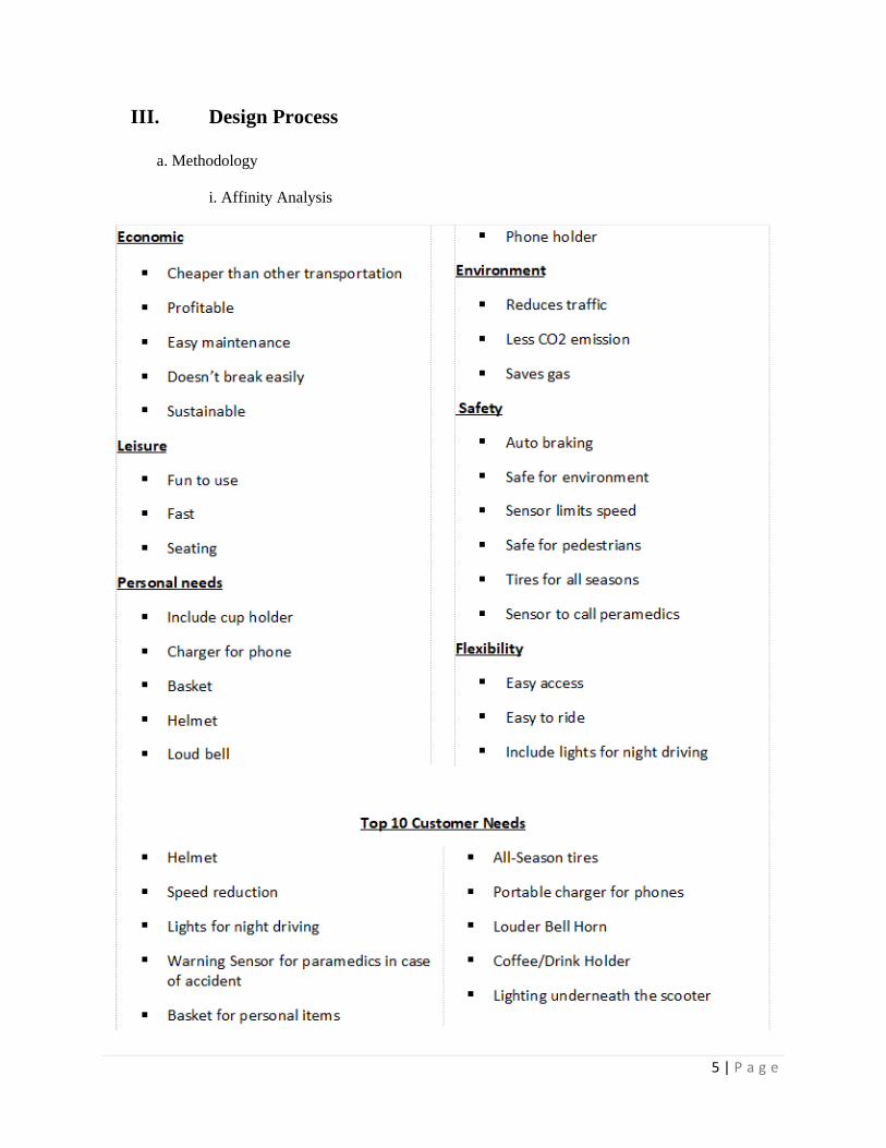
i. Affinity Analysis
6 | P a g e
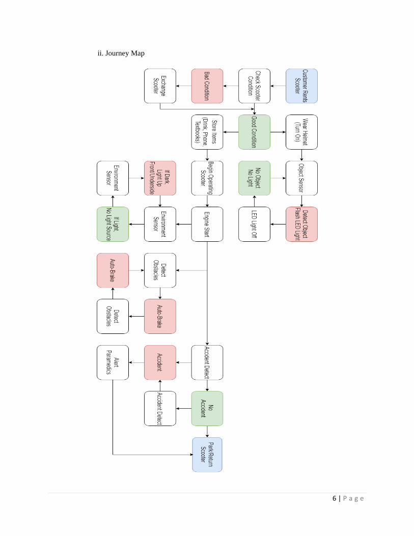
ii. Journey Map

7 | P a g e
iii. Mind Maps

8 | P a g e
iv. 6-3-5 Output

9 | P a g e
b. Constraints
• Affordability (stay within the Senior Design budget)
• Semester time constraint
c. Specifications
i. Design requirements
• Create a helmet to detect obstacles. LEDs on the helmet will indicate if an
obstacle is present.
• Detecting obstacles within a range of 50cm.
• Wireless connection between the helmet and scooter able to
transmitting/receiving data within 5 meters.
ii. Parts list
Part Quantity Unit price Total price
Arduino Uno Starter Kit 1 30 30
Arduino Uno 2 15 30
IR Sensor 2 13 26
Transceiver (NRF24L01) 2 2 4
10 | P a g e
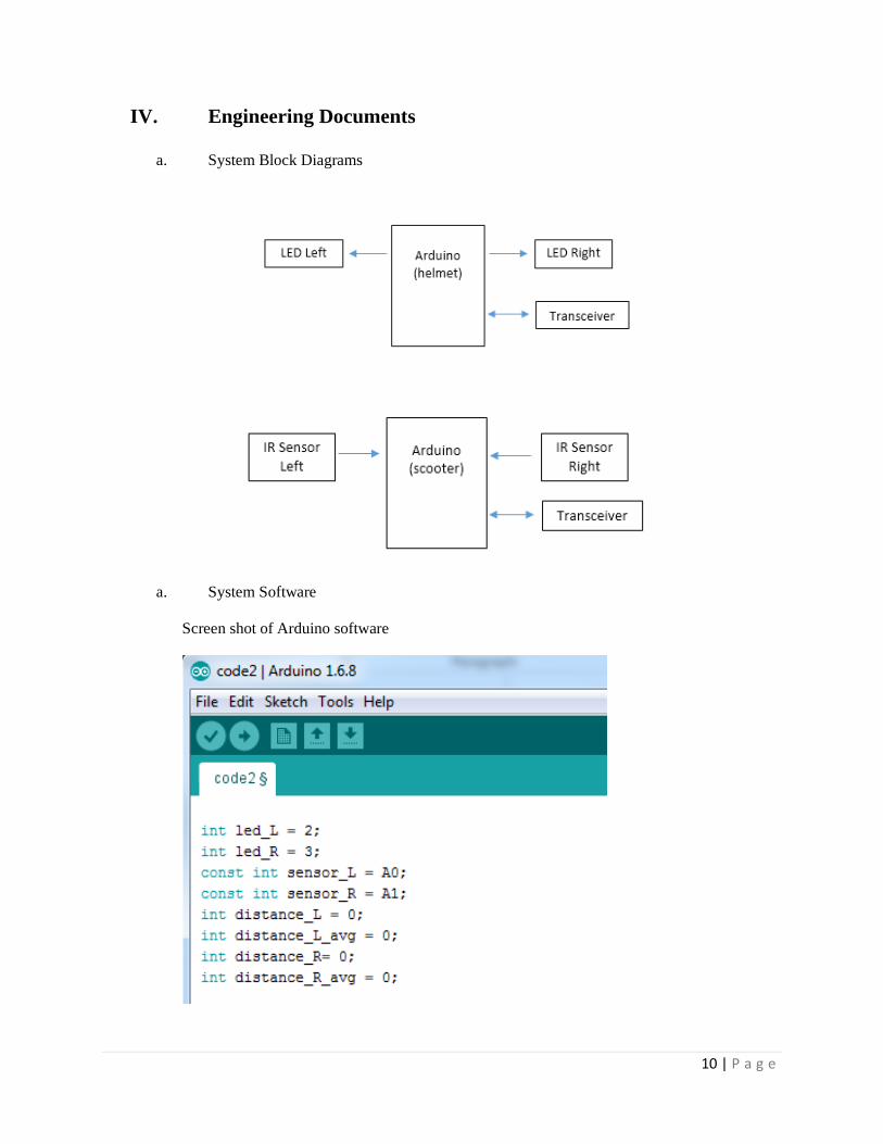
IV. Engineering Documents
a. System Block Diagrams
a. System Software
Screen shot of Arduino software

11 | P a g e
b. Gantt Chart
V. Computer Design Tools
Sample schematic for connecting the NRF24L01 to the Arduino using ORCAD’s PSPICE.
U1
arduino
3.3V1
GND2
PIN73
PIN84
PIN505
PIN516
PIN527
U2
nrf 24l01
VCC1
GND2
CSN3
CE4
SCK5
MOSI6
MISO7

12 | P a g e
VI. Patent and Standards Research
a. Research related to design
Object detection has become a common function nowadays through many devices, such
as security cameras for example, so the idea for adding sensors to a helmet wouldn’t be unheard
of. Many things use sensors to detect movement for many purposes, but the main focus of this
project is for security and safety that detection would bring. The idea for adding obstacle sensing
capabilities to a helmet adds more uniqueness to its overall function. There are countless other
patents for sensors and helmets with various purposes, including some that match the functions
included in this project. Many existing patents involve the use of sensors and lights to notify the
user of incoming objects both inanimate and living.
b. As low as 9,000 and up to 430,000+ similar patents searched through
https://www.google.com/?tbm=pts with keywords ”infrared sensor object detection helmet speed
reduction”
Patent Number Title Description
US8884229B2 Passive infrared range finding
proximity detector
detect infrared radiation emitted
by objects within a detection
area
CA2123296C Passive type moving object
detection system
detection regions for monitoring
a human intruder and a row of
detection regions for detecting a
non-human intruder
WO2017018825A1 Infrared object detecting module
and side view mirror
emits infrared rays and uses
reflected light from the emitted
infrared rays to determine
whether an object is present
EP2732440A2 Method and system for people
counting using passive infrared
detectors
detecting an object transiting an
interrogation zone of an
electronic article surveillance
("EAS") system and determining
whether the object is a person
entering or exiting the facility
US7259658B2 Passive infrared sensor and
obstacle detection system used
in the same
detects the presence of an
intruder in a security area by
receiving the infrared light that
the intruder emits
US8194920B2 Method and system for detecting
objects using far infrared images
a far IR sensor operable to sense
thermal radiation of objects and
surroundings in a field of view
13 | P a g e
US9457709B2 Bicycle helmet with an adaptive
light notification system that
varies brightness
Abstract
adaptive light notification
system and method for
activating turn signals using
sensors
VII. Proof of Concept
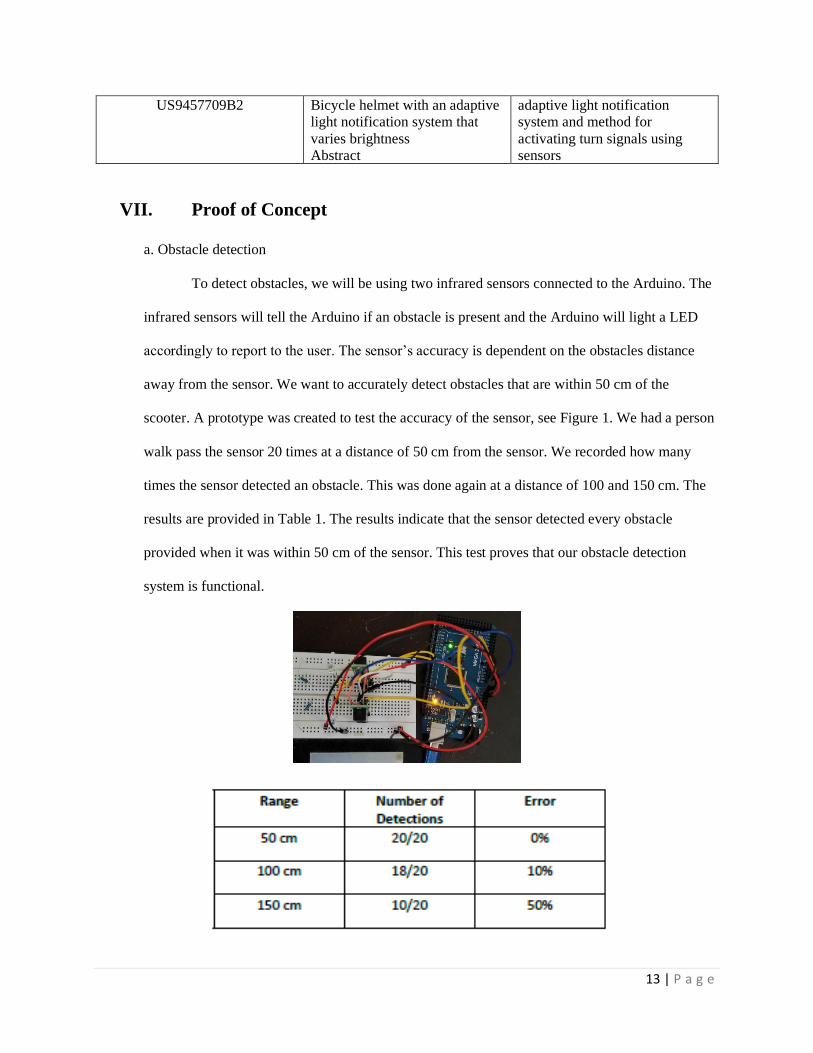
a. Obstacle detection
To detect obstacles, we will be using two infrared sensors connected to the Arduino. The
infrared sensors will tell the Arduino if an obstacle is present and the Arduino will light a LED
accordingly to report to the user. The sensor’s accuracy is dependent on the obstacles distance
away from the sensor. We want to accurately detect obstacles that are within 50 cm of the
scooter. A prototype was created to test the accuracy of the sensor, see Figure 1. We had a person
walk pass the sensor 20 times at a distance of 50 cm from the sensor. We recorded how many
times the sensor detected an obstacle. This was done again at a distance of 100 and 150 cm. The
results are provided in Table 1. The results indicate that the sensor detected every obstacle
provided when it was within 50 cm of the sensor. This test proves that our obstacle detection
system is functional.
14 | P a g e
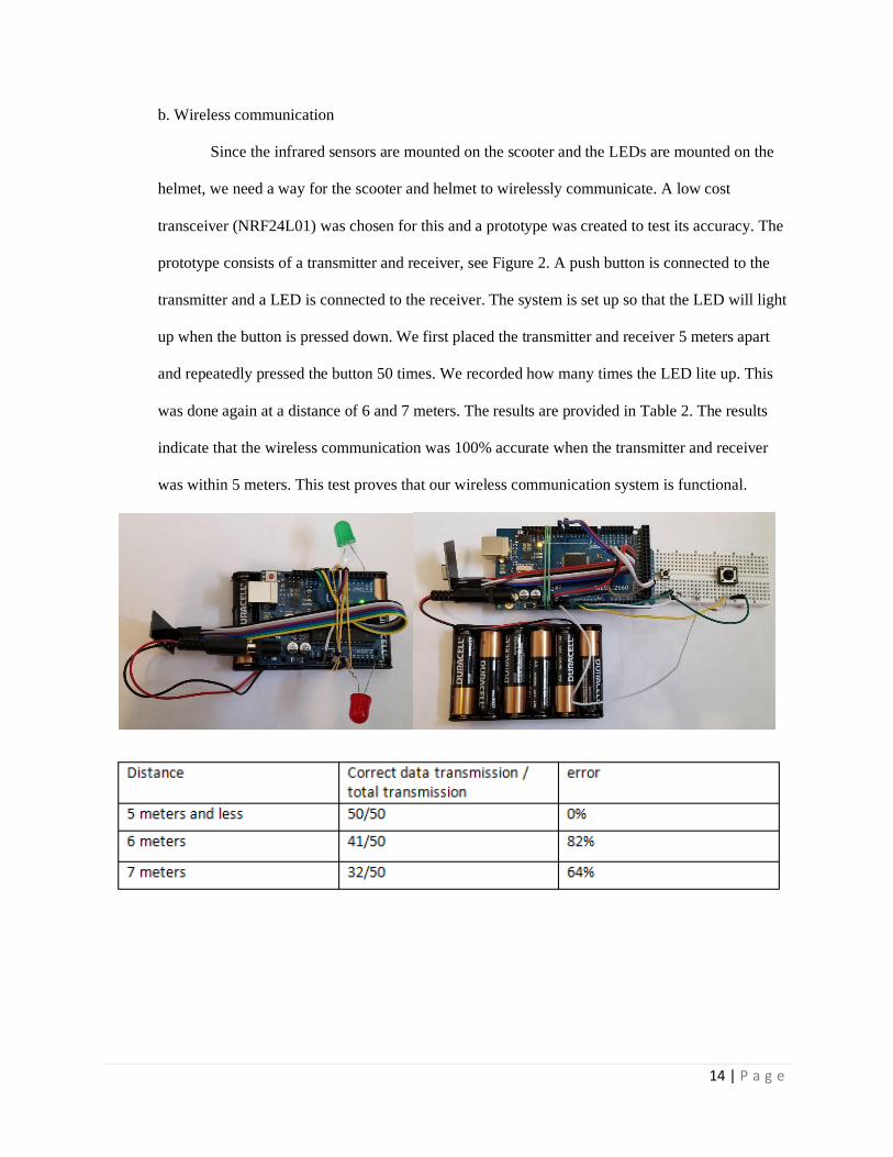
b. Wireless communication
Since the infrared sensors are mounted on the scooter and the LEDs are mounted on the
helmet, we need a way for the scooter and helmet to wirelessly communicate. A low cost
transceiver (NRF24L01) was chosen for this and a prototype was created to test its accuracy. The
prototype consists of a transmitter and receiver, see Figure 2. A push button is connected to the
transmitter and a LED is connected to the receiver. The system is set up so that the LED will light
up when the button is pressed down. We first placed the transmitter and receiver 5 meters apart
and repeatedly pressed the button 50 times. We recorded how many times the LED lite up. This
was done again at a distance of 6 and 7 meters. The results are provided in Table 2. The results
indicate that the wireless communication was 100% accurate when the transmitter and receiver
was within 5 meters. This test proves that our wireless communication system is functional.
15 | P a g e
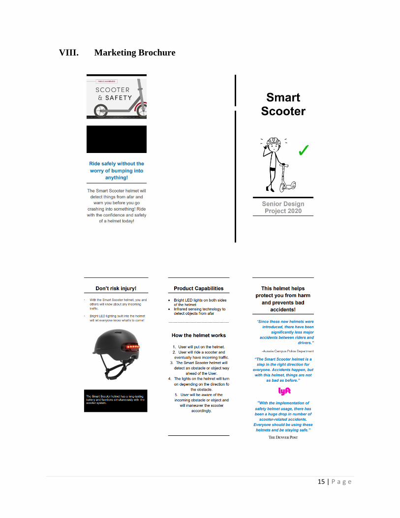
VIII. Marketing Brochure

16 | P a g e
IX. Project Design and Implementations Task and Responsibilities