elecraft xg2 receiver test oscillator xg2 manual rev g.pdf · orient the printed circuit board with...
TRANSCRIPT
ELECRAFT XG2 RECEIVER TEST OSCILLATORR e v G , J a n u a r y 1 6 , 2 0 1 8
Copyright © 2018, Elecraft, Inc., All Rights Reserved
IntroductionThe Elecraft XG2 is a crystal oscillator with accurate 1 µV and 50 µV output levels. It's ideal for receiver test and alignment. The 1-µV output can be used to measure a receiver'ssensitivity, while the 50-µV output is useful for S-meter calibration. Switch-selected output frequencies of 3579, 7040, and 14060 kHz provide convenient test signals on 80, 40, and 20 meters; harmonics of these frequencies can be used for measurements on higher bands. The XG2's unique oscillator stage runs at an extremely low level, eliminating the need for interstage shielding. A red LED is provided to indicate power-onand another red LED is provided to alert the operator to accidental transmit into the XG2's output.
SpecificationsRF Output Level 1 µV (-107 dBm) and 50 µV (-73 dBm) into 50 ohmsOutput Accuracy Better than +/- 2 dB at 25 deg. C (+/- 1 dB typical)Frequency 3579.5, 7040.0 and 14060.0 kHz +/- 2 kHz at 25 deg. C Reverse Protection 5 watts for 4 seconds, 10 watts for 2 seconds (typical; not
guaranteed)Current Drain About 250 µa from on-board 3-V, 220 mA-hr battery (est. life 800
hours)Size PC board: 3"L x 1.5"W; 4.3"L including BNC connector
Parts Inventory
Ref Qty Description Part #R2 1 Res, 18.7 k 1% (brn, gry, vio, red, brn) E500127
R3 1 Res, 16.5 Ω 1% (brn, blu, grn, gold, brn) E500122
R4 1 Res, 348 Ω 1% (org, yel, gry, blk, brn) E500124
R5 1 Res, 57.6 Ω 1% (grn, vio, blu, gold, brn) E500124
R6, R7 2 Res, 52.3 Ω 1% (grn, red, org, gold, brn) E500123
R8 1 Res, 1.24 k 1% (brn, red, yel, brn, brn) E500126(parts inventory continues on next page)
Elecraft • www.elecraft.com • 831 763-42111
Ref Qty Description Part #
R1, R9 2 Res, 10 k 5% (brn, blk, org) E500015
R13 1 Res, 5.6K 5%, (grn,blu,red) E500007
C2, C5 2 Mono Cap, 47 pF (47 or 470) E530014
C1 1 Mono Cap, 18 pF (18 or 180) E530212
C3, C4 2 Mono Cap, .047 µF (473) E530131
C6 1 Mono Cap, 33 pF (33 or 330) E530013
D5 1 Red LED, round E570025
D2 1 Red LED, rectangular E570007
D1, D4 2 Diode, 1N4148 E560002
U1 1Ref. Diode, 1.22 V, ZXRE125DR or ZXRE1004D
E600081
Q1 1 Transistor, 2N3904 E580017
X1 1 Crystal, 14060 kHz E850211
X2 1 Crystal, 7040 kHz E660023
X3 1 Crystal, 3579.545 kHz E660029
BT1 1Lithium 3V battery, CR2032 (Inside envelope E850058)
E980039
S1 1 Miniature slide switch E640009
J1 1 BNC Connector E620020
S2 1 Large slide switch E640019
S3 1 Rotary switch, 3 position E640027
Misc. 3 Self-adhesive mounting feet E700024
Misc. 1 Battery Holder E980086
Misc. 1 XG2 Printed Circuit Board E100255
Assembly
Sort the resistors by value. Some of the color bands may be hard to read; use a magnifying glass if necessary. A Digital Multimeter (DMM) should be used to confirm the values.
2

Orient the printed circuit board with the silk-screened side up and the title “XG2” at the bottom.
Install the following resistors in their indicated positions, starting at the top of the PC board and working down. (Complete the left column, below, then the right column.) Note: The XG2's output level accuracy depends on each resistor being installed in the correct location.
Sort the small ceramic capacitors by value. Install the capacitors listed below: __ C3, .047µF (473)
__ C4, .047µF (473) __ C2, 47pF (470)
__ C1, 18pF (180) __ C5, 47pF (470) __ C6, 33pF (330)
Using your DMM, measure the resistance to ground at each of the points listed below. Any incorrect reading could indicate that you have one or more resistors installed incorrectly.
__ junc. of R7, R8: 48-52 ohms __ junc. of R6, R8: 48-52 ohms __ junc. of C4, R4: 385-425 ohms __ junc. of C1, C2, R2: 18-19 k
Install diode D1 (1N4148) with the banded end nearest resistor R7. NOTE: The silk-screened outline and band on the Rev A board is backwards!
Install diode D4 (1N4148). The outline for this diode is correct. Align the banded end with the band on the silk-screened outline. The band will be at the end nearest the edge ofthe board.
Install the Red LED at D2. Insert the long lead into the square pad.
Install the small round LED at D5. Insert the long lead into the square pad.
Install J1, the BNC connector, on the edge of the board as shown by its outline (see right side photo on page 8).
Install the battery holder for BT1.
Install switches S1, S2 and S3 in their indicated positions.
3
__ R7, 52.3 Ω, 1% (grn, red, org, gold, brn)__ R8, 1.24 k, 1% (brn, red, yel, brn, brn)__ R6, 52.3 Ω, 1% (grn, red, org, gold, brn)__ R5, 57.6 Ω, 1% (grn, vio, blu, gold, brn)__ R4, 348 Ω, 1% (org, yel, gry, blk, brn)
__ R3, 16.5 Ω, 1% (brn, blu, grn, gold, brn)__ R2, 18.7 k, 1% (brn, gray, vio, red, brn)__ R1, 10 k, 5% (brn, blk, org)__ R9, 10 k, 5% (brn, blk, org)__ R13, 5.6k 5% (grn, blu, red)

Install U1 and Q1. Align the flat side of the packages with the flat side shown on the component outline. Note: When U1 is correctly installed, its labeled side will face away from S2.
Mount the crystals, X1, X2 and X3 in their indicated positions.
Solder a scrap of wire to the top of each crystal case, and solder the other end of this wireto the square pads near BT1. Limit soldering time to 3 seconds, since excessive heat maydamage the crystal.
Install 3 mounting feet on the back side of the board as shown in the left side photo on page 8.
Initial Test
Set S1 (small slide switch) to the OFF position.
Set S3 to the “40” position.
Set S2 (large slide switch) to the 50 µV position.
Install the Lithium battery into its holder. Make sure that the (+) side of the battery is UP.
If the unit to be tested is a transceiver, set its power output for minimum and disconnect the key, keyer, and microphone to prevent accidental transmit into the XG2's output jack.
Connect the output of the XG2 to the antenna jack of the receiver or transceiver.
Tune the receiver to 7040 kHz. DO NOT TRANSMIT.
Turn on the XG2. The round red LED will light.
The XG2 output should be heard on the receiver.
Turn the XG2 off to conserve battery life.
4

Using the XG2
Indicator LEDs
Power-on LED (red): Turns ON when the XG2 is in use and the battery voltage is satisfactory. Turns OFF if the battery voltage falls below about 2.4 volts. If this happens, change the battery to ensure accurate output levels.
Transmit warning LED (red): Turns ON as a warning if you accidentally transmit into the XG2's output jack at 100 milliwatts or more. Note: Some protection is provided by the back-to-back diode limiter formed by D2 (red LED) and D1. This circuit has been tested at up to 10 watts for 2 seconds.
5

Applications
A 50-µV signal is a commonly-accepted level for "S9," and a 1-µV signal is often used to measure signal-to-noise ratio to evaluate the sensitivity of a receiver (see procedures starting on next page). The XG2 can be used to evaluate a new receiver, check the condition of an old receiver, or check a receiver after exposure to lightning or other traumatic events. A homebrew receiver’s sensitivity is easily measured, and design choices can be evaluated to improve the design. Since the XG2 is self-powered, lightweight and small in size, it's an ideal tool to take to a flea market to evaluate used gear.
Receiver Sensitivity Testing (Using 1 µV Signal)
The XG2 can be used to test absolute receiver sensitivity, providing a means of comparing various receivers or transceivers. The instructions below apply to any type of receiver or transceiver, but we've included settings for the Elecraft K1 and K2. 1. If you're testing a transceiver, turn its power output level to minimum as a precaution, and disconnect the key or keyer and mic. If you're using an ATU, put it into bypass mode (CAL or CALS on Elecraft tuners).
2. Connect the XG2 to the antenna jack on the receiver (or transceiver). You can connect the XG2directly to receiver or transceiver using a suitable adapter, such as our model BNC-MM .
NOTE: Keep your hands and other objects away from the XG2 during measurements, as this may affect the output signal level, especially at the 1-microvolt setting.
3. Turn AGC OFF if possible. (K2, hold PRE+AGC switches. K1, use AGC menu entry.)
4. Set RF GAIN to maximum.
5. Turn off the attenuator.
6. Turn on the preamp. NOTE: Preamp OFF tests may also be useful.
7. Select CW mode, narrow passband if available ("CW-N" on some rigs).
8. If possible, set the filter bandwidth for about 500 Hz, the standard for lab receiver tests. (K2, use FLx = 0.70, which corresponds to about 500 Hz. For the K1, use FLx = 500.)
9. Turn off, bypass, or widen the audio filter if applicable. (K2: see KAF2 or KDSP2 manual.)
10. Connect the probes of a digital multimeter (DMM) across the speaker terminals. Set the DMM for 2 or 3 volts AC (or RMS) full-scale. (K2: Connect the DMM across the internal speaker or the external speaker jack. If you use the headphone jack, don't plug in headphones at the same time, since this will form voltage dividers with R35 and R36, lowering the AC voltage reading.)
6

11. Set the receiver or transceiver for about the XG2 output frequency that you have selected.
12. Turn on the XG2 and set it for 1 microvolt output. Replace the battery if the power-on LED does not light.
13. Locate the XG2 signal with the receiver. Peak the signal in the crystal filter passband.
NOTE: BFO settings can affect sensitivity. If the passband peak occurs at a pitch well outside theexpected range (typically 500-800 Hz), you may need to realign your BFO settings using an appropriate method (K2: see application notes on our web site).
14. Set the AF GAIN control fully clockwise (if this results in a signal that is loud enough to damage the speaker or cause distortion, use a reduced setting, but make sure you use the same setting each time).
15. Note the DMM's reading: _______ Vrms (this is the S+N, or signal+noise reading). NOTE: This value is useful for comparing overall receiver gain with that of a reference receiver.
16. Turn off the XG2 and note the new reading: _______ Vrms (this is the N or noise reading).
Signal-to-Noise And MDS Calculations
Using the results from the previous page, you can calculate the signal-to-noise to noise ratio (S+N/N) at 1 microvolt, and estimate the MDS (minimum discernable signal) as follows:
A. Divide S+N by N; call the resulting ratio R.B. Take the base-10 logarithm of R ("log" key on most calculators).C. Multiply the result by 20 to obtain the S+N/N ratio at 1 microvolt, in dB.D. If the S+N/N is greater than 10 dB, then the MDS is approximately equal to the result from (C) subtracted from -107 dBm.
Example: DMM readings of 1.0 Vrms (XG2 on), and 0.030 Vrms (XG2 off).
A. R = 1.0/.03 = 33B. log(33) = 1.52C. 20 x 1.52 = about 30 dB (this meets the requirement for step D)D. MDS = -107 dBm - 30 dB = -137 dBm
A K2 should produce a S+N (XG2 on) reading of roughly 0.4-0.8 Vrms, and more importantly, an MDS of about -135 dB or better. With an audio filter installed, the S+N and N readings may be higher, especially if you've modified the gain settings, but the MDS should be about the same. Many factors can affect the S+N and N readings, including whether a KSB2 or KNB2 is installed,which band is selected, how the band-pass filters and BFOs are aligned, how L34 is adjusted, andwhether the 2nd XFIL modification has been made (already present in K2s with S/N 3000 and
7
higher). If the estimated MDS value is lower than expected, make sure that you have the preamp on, AGC off, ATU in bypass mode, and RF GAIN set fully clockwise.
A K1 should produce a S+N (XG2 on) reading of roughly 0.1-0.2 Vrms, and an MDS of about -130 dB.
S-Meter Calibration (Using 50 µV Signal)
50 microvolts is widely used as the standard for an S-meter reading of "S-9". The manufacturer ofyour receiver or transceiver may prefer a different level; consult its manual. Also note that S-meter readings are relative. On some transceivers, including the Elecraft K2, turning the preamp off or the attenuator on will drop the indicated value. (The K1 adds one bar to the reading if the attenuator is turned on.)
To align your S-meter at 50 microvolts:
1. Set up the receiver or transceiver as indicated in steps 1-13 on the previous page. In this case, there's no need to turn AF GAIN to maximum.
2. Turn the AGC on (K2, hold PRE+AGC switches. K1, use AGC menu entry).
3. Switch the XG2 to its 50-microvolt setting.
4. Adjust the S-meter "scale" value such that the S-meter indicates S-9. (K2, use CAL S HI function. K1, use SIG menu entry, "H" parameter. The K1 does not have a labeled S-meter scale; use 4 bars for S-9.)
5. Turn the XG2 off. The S-meter reading should now drop to approximately zero (1 bar may be flickering on/off). If not, adjust the S-meter's "zero" value. (K2, use CAL S LO. K1, use SIG, "L"parameter.) Repeat steps 4 and 5 if necessary.
Circuit Description
The XG2 produces a signal at with very accurate amplitude. Unlike most signal generators capable of accurate 1-µV output, the XG2 requires no shielding. This is due to the extremely low power level of the crystal oscillator, as well as careful PC board layout and component selection. The output of the oscillator (-50 dBm or 10 nanowatts into 50 ohms) is attenuated by 23 dB to obtain the 50-µV test signal. An additional 34 dB attenuator stage is placed in series with the signal path by switch S2 when an output level of 1 µV is needed. Output accuracy is determined by the precision voltage regulator and 1% resistors.
8
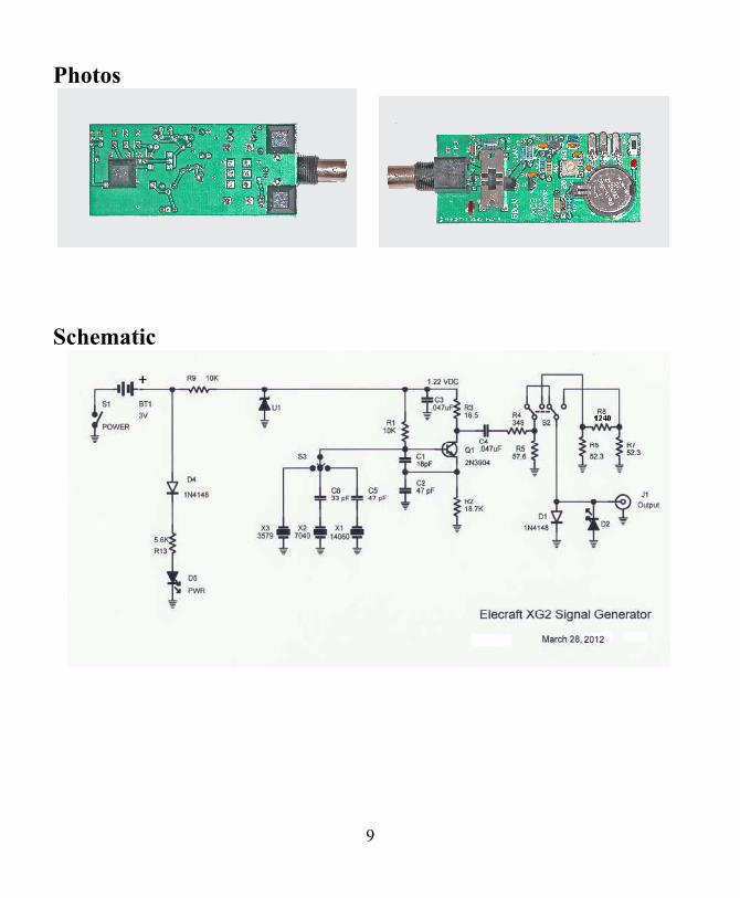
Photos
Schematic
9