electric circuits basics. electricity basics electricity starts with electrons. every atom contains...
TRANSCRIPT
ELECTRIC CIRCUITS BASICS
Electricity Basics
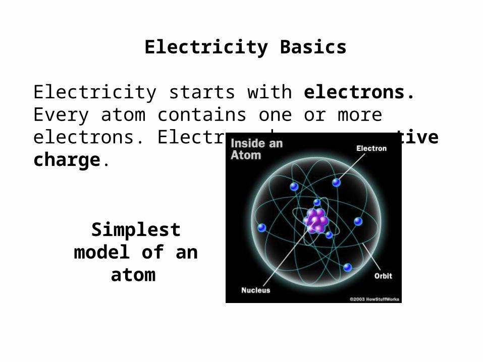
Electricity starts with electrons. Every atom contains one or more electrons. Electrons have a negative charge.
Simplest model of an atom

A Copper Atom
Electrons (29 total)
Protons (29 total)Valence Ring(Outer Ring)
Atoms will have the same number of Electrons in the orbit as there are Protons in the center.
But most metals have electrons that can detach from their atoms and move around. These are called free electrons. Gold, silver, copper, aluminum, iron, etc., all have free electrons. The loose electrons make it easy for electricity to flow through these materials, so they are known as electrical conductors. They conduct electricity. The moving electrons transmit electrical energy from one point to another.
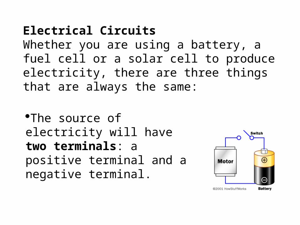
Electrical CircuitsWhether you are using a battery, a fuel cell or a solar cell to produce electricity, there are three things that are always the same:
The source of electricity will have two terminals: a positive terminal and a negative terminal.
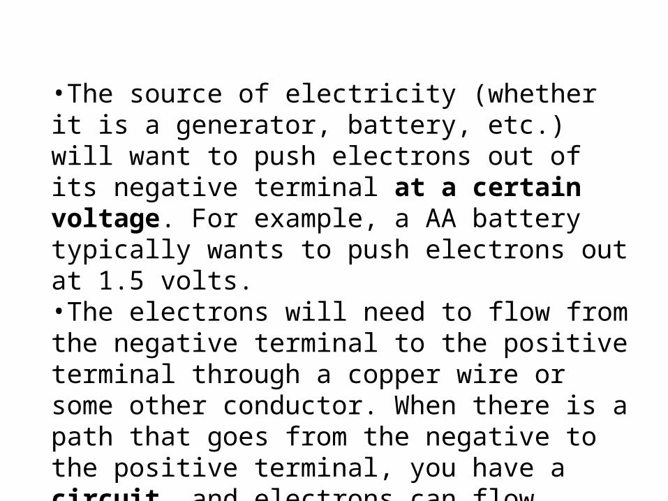
•The source of electricity (whether it is a generator, battery, etc.) will want to push electrons out of its negative terminal at a certain voltage. For example, a AA battery typically wants to push electrons out at 1.5 volts.•The electrons will need to flow from the negative terminal to the positive terminal through a copper wire or some other conductor. When there is a path that goes from the negative to the positive terminal, you have a circuit, and electrons can flow through the wire.
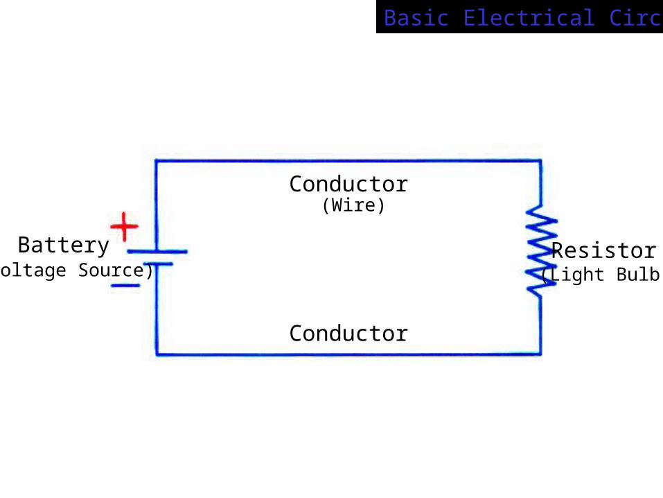
Basic Electrical Circuits
Battery
Conductor
Conductor
Resistor(Voltage Source) (Light Bulb)
(Wire)

+++
- -
-
+++
- -
-
+++
- -
-
+++
- -
-
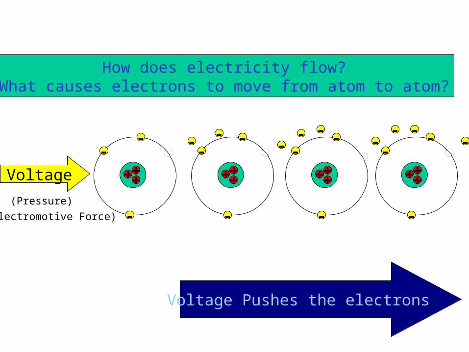
Voltage
(Pressure)
(Electromotive Force)
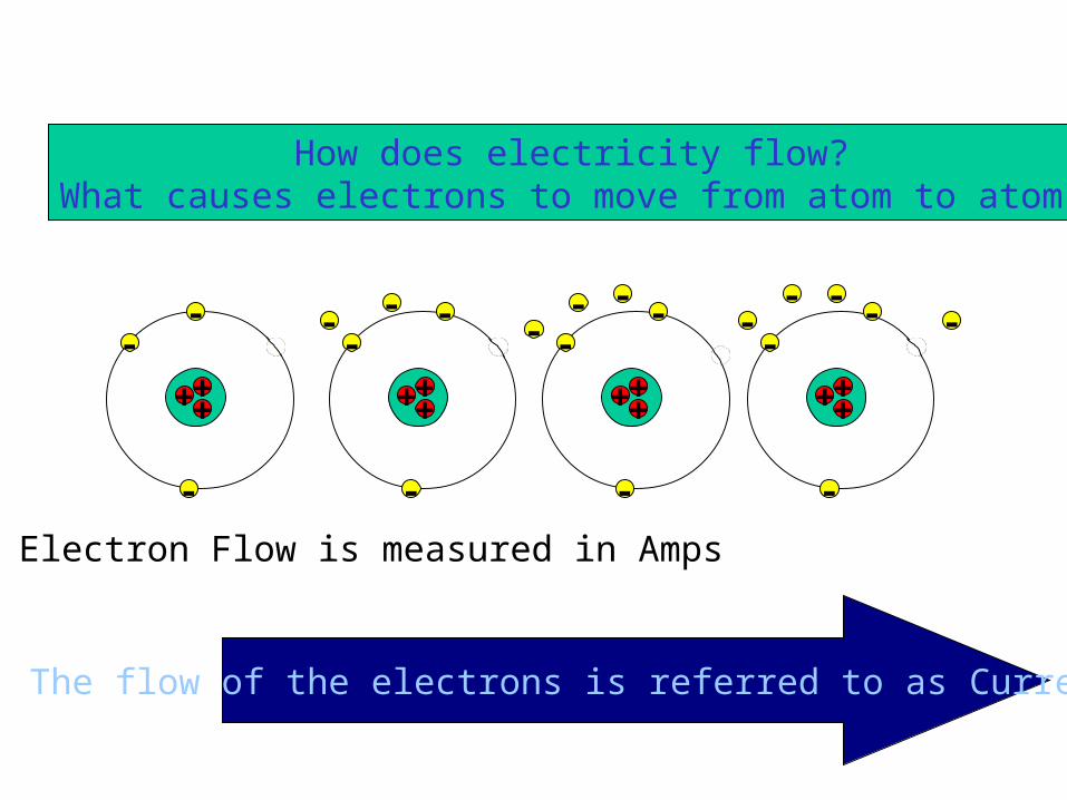
How does electricity flow?What causes electrons to move from atom to atom?
Voltage Pushes the electrons Voltage Pushes the electrons Voltage Pushes the electrons Voltage Pushes the electrons Voltage Pushes the electrons
+++
-
-
+++
-
-
+++
-
-
+++
-
-
Voltage
(Pressure)
(Electromotive Force)
--
- - -- -
- - --
-- - -
--
Voltage Pushes the electrons
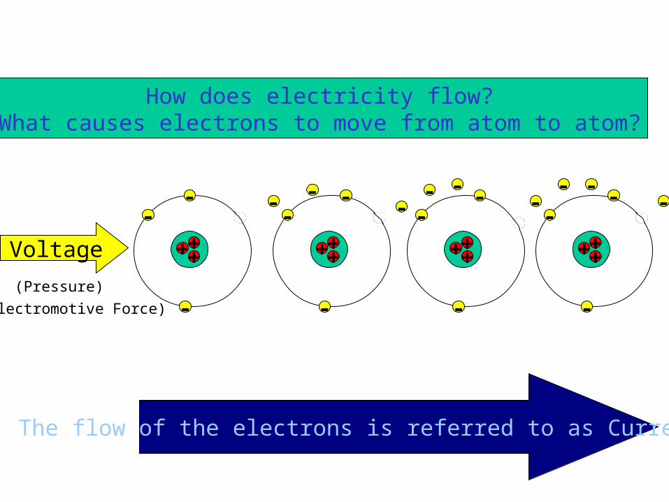
How does electricity flow?What causes electrons to move from atom to atom?

+++
-
-
+++
-
-
+++
-
-
+++
-
-
--
- - -- -
- - --
-- - -
--
Voltage Pushes the electrons
How does electricity flow?What causes electrons to move from atom to atom?
+++
-
-
+++
-
-
+++
-
-
+++
-
-
Voltage
(Pressure)
(Electromotive Force)
--
- - -- -
- - --
-- - -
--
The flow of the electrons is referred to as Current
How does electricity flow?What causes electrons to move from atom to atom?
+++
-
-
+++
-
-
+++
-
-
+++
-
-
--
- - -- -
- - --
-- - -
--
How does electricity flow?What causes electrons to move from atom to atom?
The flow of the electrons is referred to as Current
Electron Flow is measured in Amps
Electric Circuits
Now that we have the concept of voltage, we can use this concept to understand electric circuits.
Just like we can use pipes to carry water, we can use wires to carry electricity. The flow of water through pipes is caused by pressure differences, and the flow is measured by volume of water per time.
Electric CircuitsIn electricity, the concept of voltage will be
like pressure. Water flows from high pressure to low pressure; electricity flows from high voltage(higher potential) to low voltage(lower potential).
But what flows in electricity? Charges!
How do we measure this flow? By Current:
current = I = q / t
UNITS: Amp(ere) = Coulomb / second

Electrical Network• A combination of various electric
elements (Resistor, Inductor, Capacitor, Voltage source, Current source) connected in any manner what so ever is called an electrical network. We may classify circuit elements in two categories, passive and active elements.
Active Elements• The elements that supply energy to the
circuit is called active element. Examples of active elements include voltage and current sources, generators, and electronic devices that require power supplies.

Passive Elements• The element which receives energy (or
absorbs energy) and then either converts it into heat (R) or stored it in an electric (C) or magnetic (L ) field is called passive element.
18
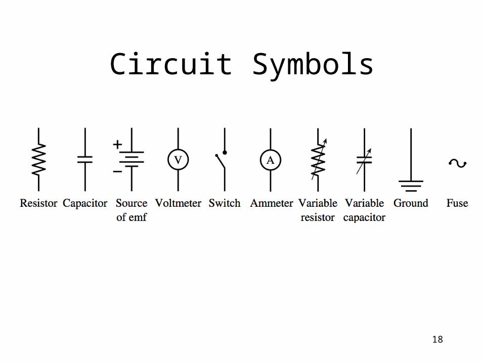
Circuit Symbols
Voltage Sources:batteries and power supplies
A battery or power supply supplies voltage. This is analogous to what a pump does in a water system.
Question: Does a water pump supply water? If you bought a water pump, and then plugged it in (without any other connections), would water come out of the pump?
Question: Does the battery or power supply actually supply the charges that will flow through the circuit?

Voltage Sources:batteries and power supplies
Just like a water pump only pushes water (gives energy to the water by raising the pressure of the water), so the voltage source only pushes the charges (gives energy to the charges by raising the voltage of the charges).
Just like a pump needs water coming into it in order to pump water out, so the voltage source needs charges coming into it (into the negative terminal) in order to “pump” them out (of the positive terminal).
Circuit ElementsIn this first part of the course we will consider two
of the common circuit elements:
resistor capacitor
inductor
The resistor is an element that “resists” the flow of electricity.
The capacitor is an element that stores charge for use later (like a water tower).
Inductor stores charge in the form of magnetic field
Resistance
Current is somewhat like fluid flow. Recall that it took a pressure difference to make the fluid flow due to the viscosity of the fluid and the size (area and length) of the pipe. So to in electricity, it takes a voltage difference to make electric current flow due to the resistance in the circuit.
Resistance
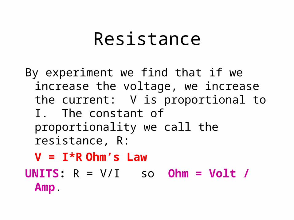
By experiment we find that if we increase the voltage, we increase the current: V is proportional to I. The constant of proportionality we call the resistance, R:
V = I*R Ohm’s Law
UNITS: R = V/I so Ohm = Volt / Amp.
Resistance
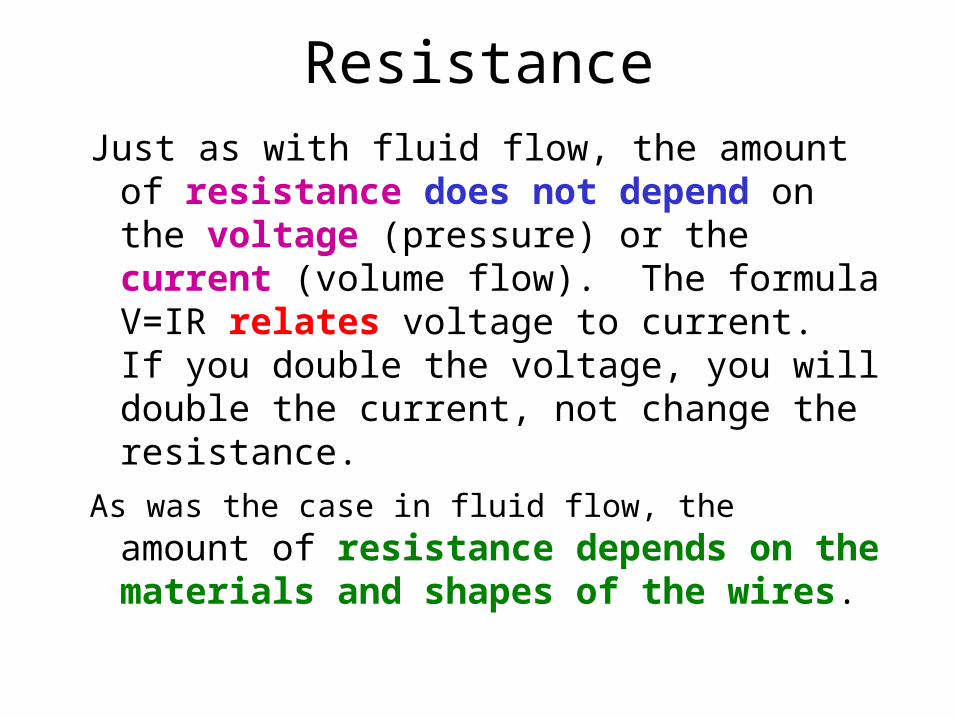
Just as with fluid flow, the amount of resistance does not depend on the voltage (pressure) or the current (volume flow). The formula V=IR relates voltage to current. If you double the voltage, you will double the current, not change the resistance.
As was the case in fluid flow, the amount of resistance depends on the materials and shapes of the wires.

Resistance
The resistance depends on material and geometry (shape). For a wire, we have:
R = L / A
where is called the resistivity (in Ohm-m) and measures how hard it is for current to flow through the material, L is the length of the wire, and A is the cross-sectional area of the wire. The second lab experiment deals with Ohm’s Law and the above equation.
Electrical Power
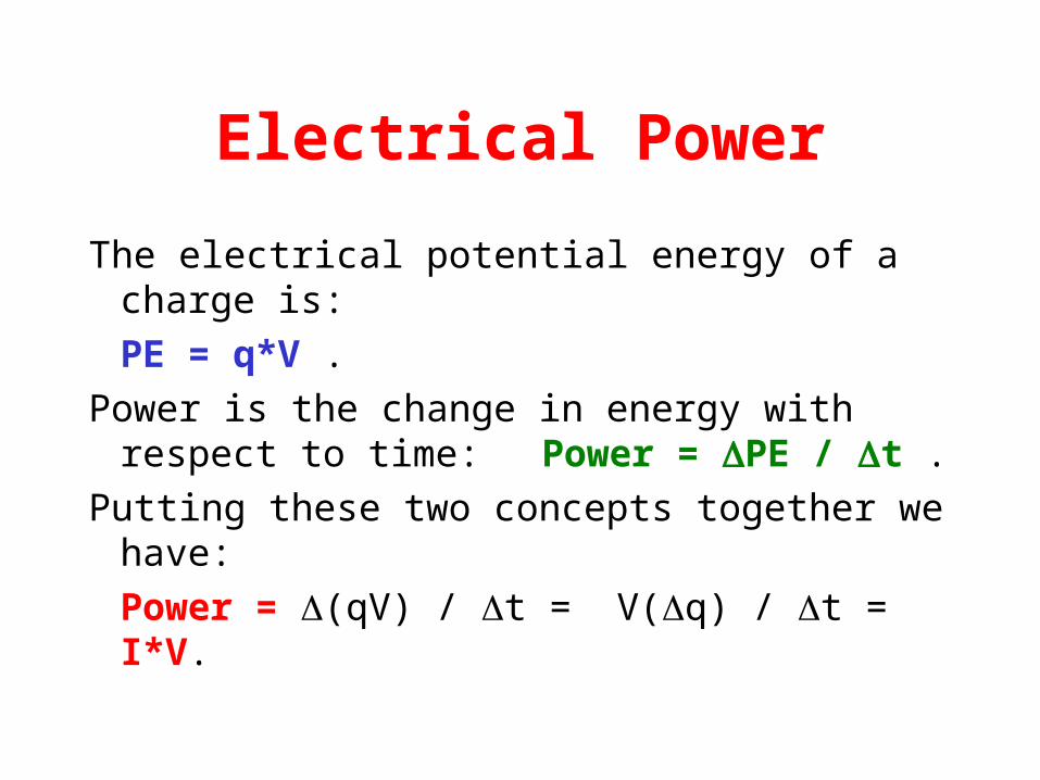
The electrical potential energy of a charge is:
PE = q*V .
Power is the change in energy with respect to time: Power = PE / t .
Putting these two concepts together we have:
Power = (qV) / t = V(q) / t = I*V.
Electrical Power
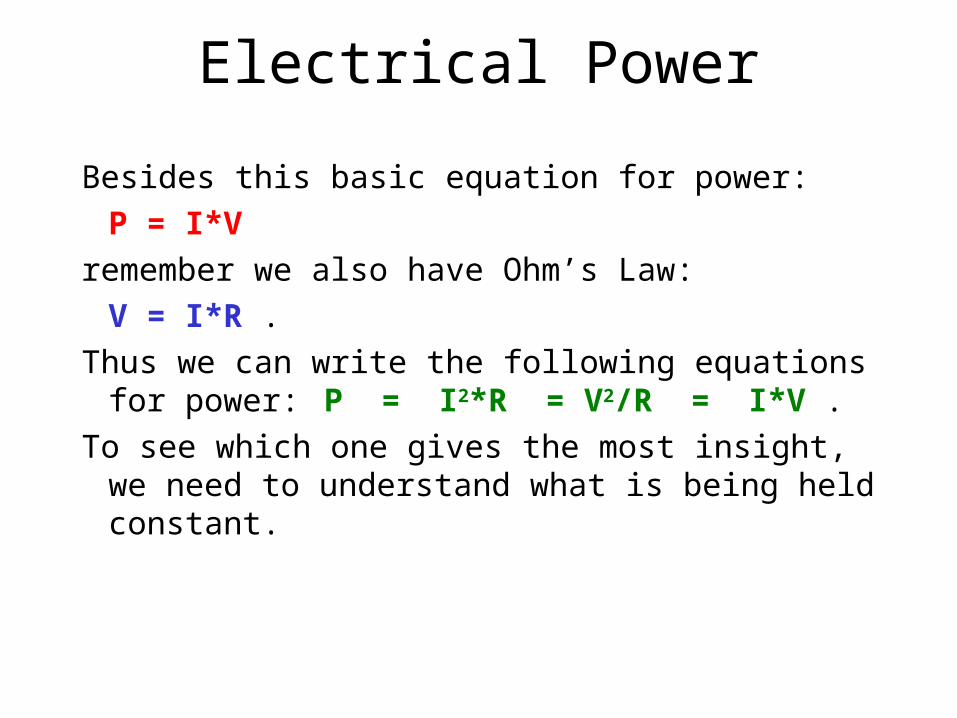
Besides this basic equation for power:
P = I*V
remember we also have Ohm’s Law:
V = I*R .
Thus we can write the following equations for power: P = I2*R = V2/R = I*V .
To see which one gives the most insight, we need to understand what is being held constant.
Example
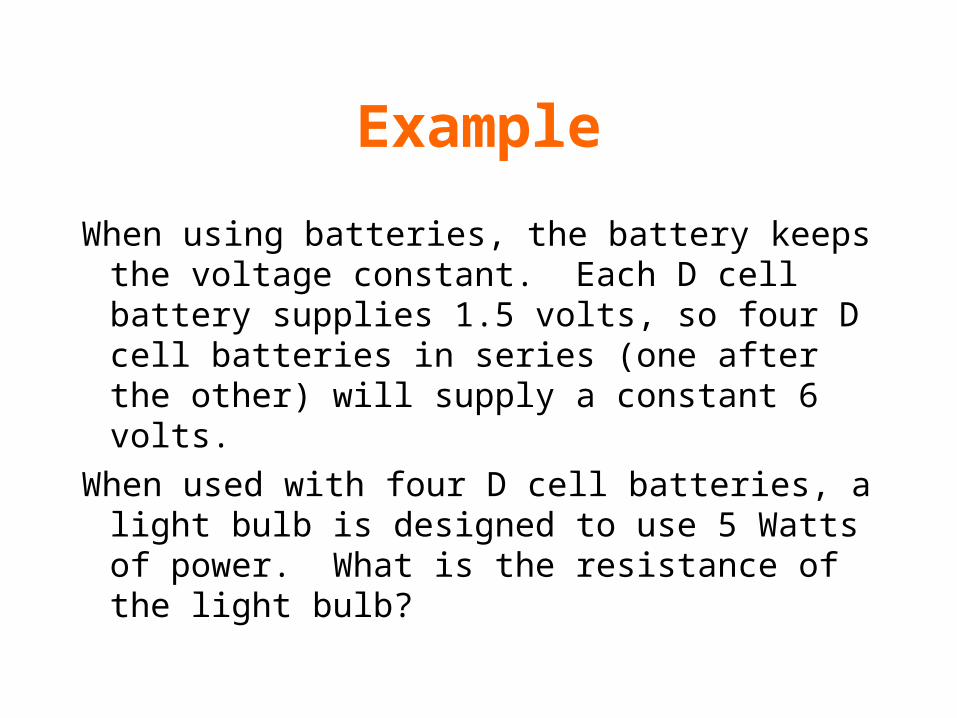
When using batteries, the battery keeps the voltage constant. Each D cell battery supplies 1.5 volts, so four D cell batteries in series (one after the other) will supply a constant 6 volts.
When used with four D cell batteries, a light bulb is designed to use 5 Watts of power. What is the resistance of the light bulb?
Example
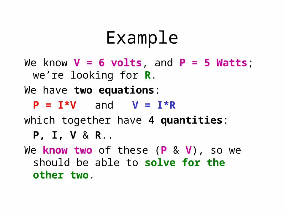
We know V = 6 volts, and P = 5 Watts; we’re looking for R.
We have two equations:
P = I*V and V = I*R
which together have 4 quantities:
P, I, V & R..
We know two of these (P & V), so we should be able to solve for the other two.
Example
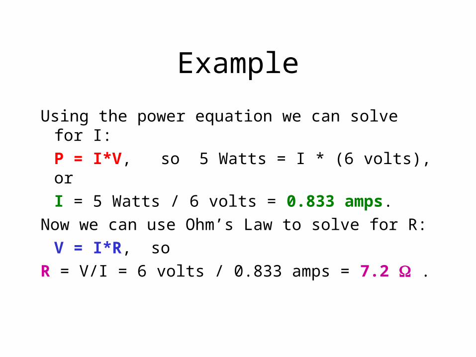
Using the power equation we can solve for I:
P = I*V, so 5 Watts = I * (6 volts), or
I = 5 Watts / 6 volts = 0.833 amps.
Now we can use Ohm’s Law to solve for R:
V = I*R, so
R = V/I = 6 volts / 0.833 amps = 7.2 .
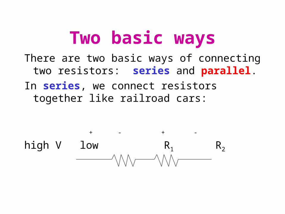
Two basic waysThere are two basic ways of connecting two resistors:
series and parallel.
In series, we connect resistors together like railroad cars:
+ - + -
high V low R1 R2
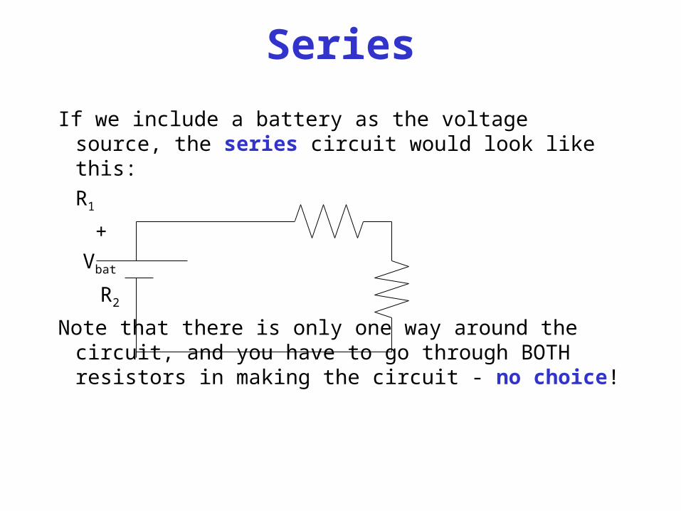
Series
If we include a battery as the voltage source, the series circuit would look like this:
R1
+
Vbat
R2
Note that there is only one way around the circuit, and you have to go through BOTH resistors in making the circuit - no choice!
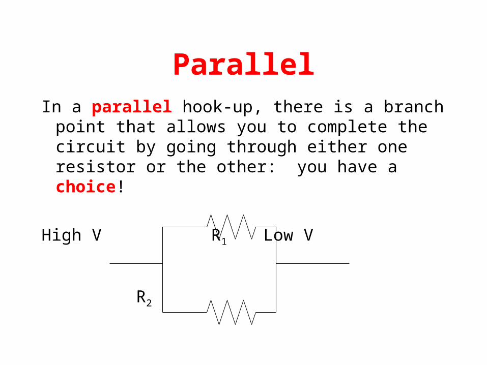
ParallelIn a parallel hook-up, there is a branch point that
allows you to complete the circuit by going through either one resistor or the other: you have a choice!
High V R1 Low V
R2
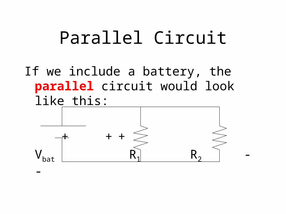
Parallel Circuit
If we include a battery, the parallel circuit would look like this:
+ + +
Vbat R1 R2
- -
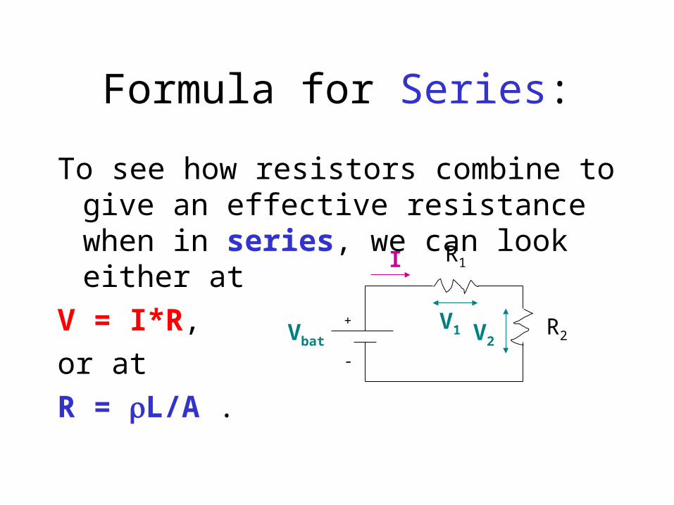
Formula for Series:
To see how resistors combine to give an effective resistance when in series, we can look either at
V = I*R,
or at
R = L/A .Vbat
R1
R2+
-
I
V1 V2
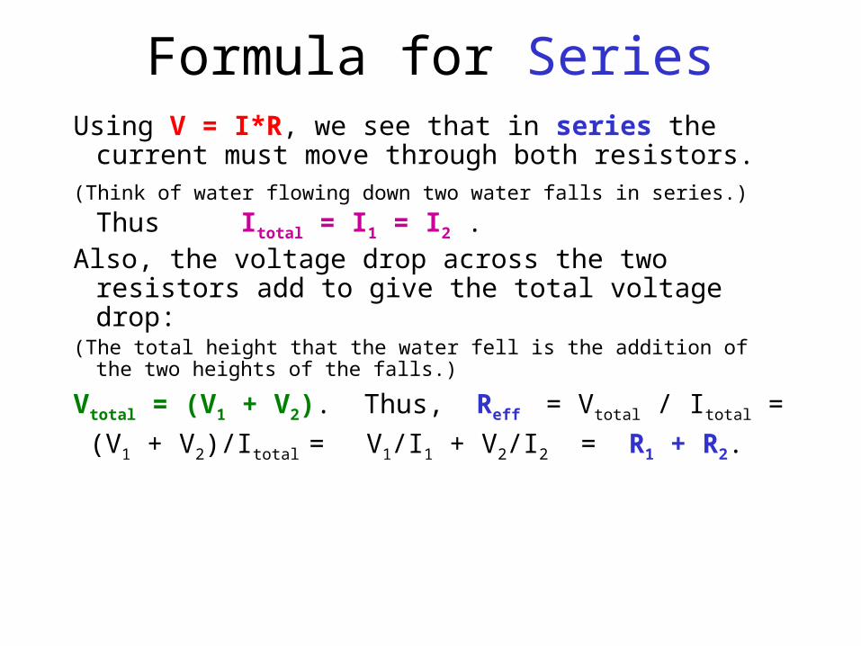
Formula for SeriesUsing V = I*R, we see that in series the current must
move through both resistors. (Think of water flowing down two water falls in series.) Thus
Itotal = I1 = I2 .Also, the voltage drop across the two resistors add to
give the total voltage drop:(The total height that the water fell is the addition of the two heights of
the falls.)
Vtotal = (V1 + V2). Thus, Reff = Vtotal / Itotal =
(V1 + V2)/Itotal = V1/I1 + V2/I2 = R1 + R2.
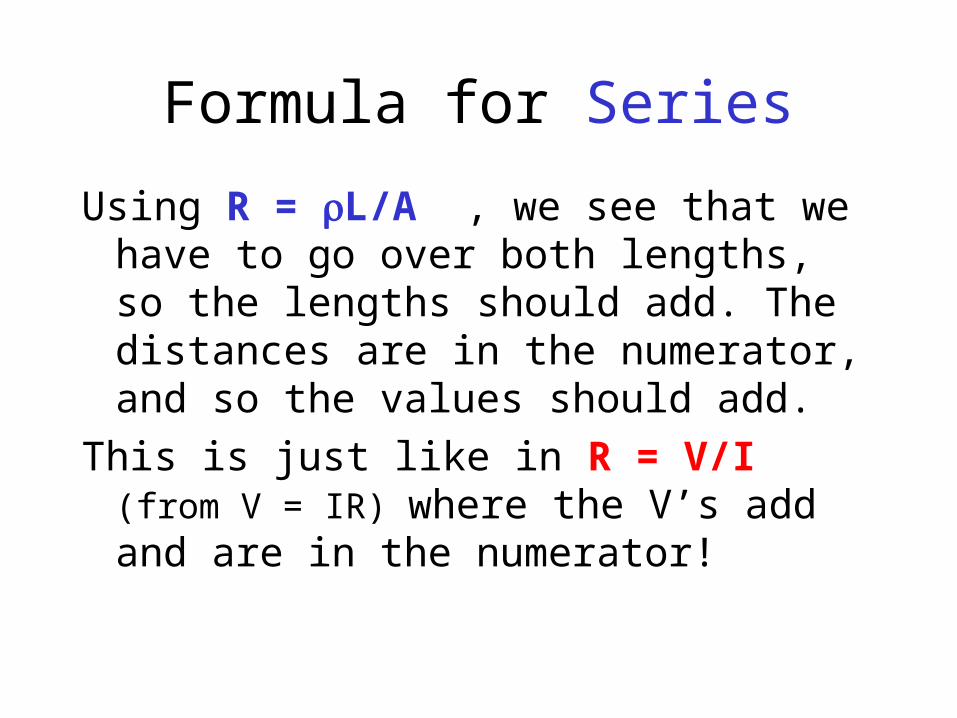
Formula for Series
Using R = L/A , we see that we have to go over both lengths, so the lengths should add. The distances are in the numerator, and so the values should add.
This is just like in R = V/I (from V = IR) where the V’s add and are in the numerator!
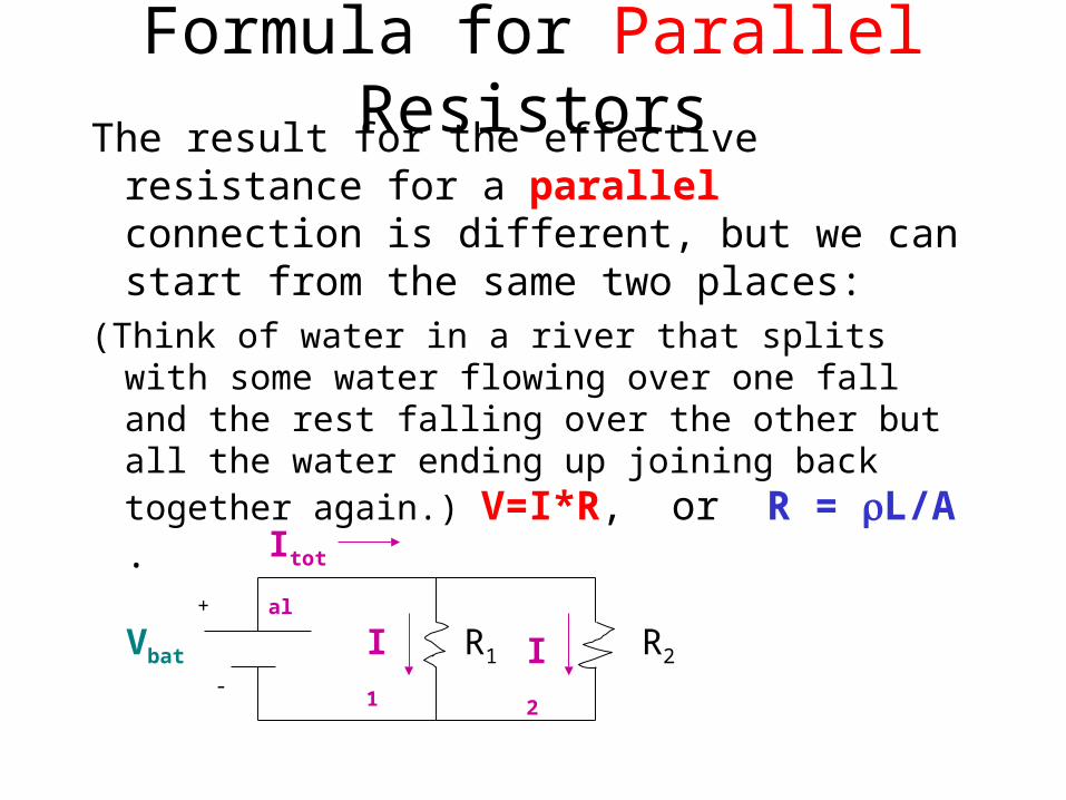
Formula for Parallel ResistorsThe result for the effective resistance for a
parallel connection is different, but we can start from the same two places:
(Think of water in a river that splits with some water flowing over one fall and the rest falling over the other but all the water ending up joining back together again.) V=I*R, or R = L/A .
+
-
Vbat R1 R2
Itotal
I1 I2
Formula for Parallel Resistors
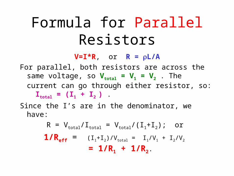
V=I*R, or R = L/A
For parallel, both resistors are across the same voltage, so Vtotal = V1 = V2 . The current can go through either resistor, so: Itotal = (I1 + I2 ) .
Since the I’s are in the denominator, we have:
R = Vtotal/Itotal = Vtotal/(I1+I2); or
1/Reff = (I1+I2)/Vtotal = I1/V1 + I2/V2 = 1/R1 + 1/R2.
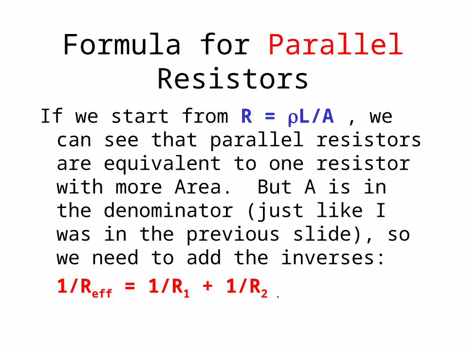
Formula for Parallel Resistors
If we start from R = L/A , we can see that parallel resistors are equivalent to one resistor with more Area. But A is in the denominator (just like I was in the previous slide), so we need to add the inverses:
1/Reff = 1/R1 + 1/R2 .
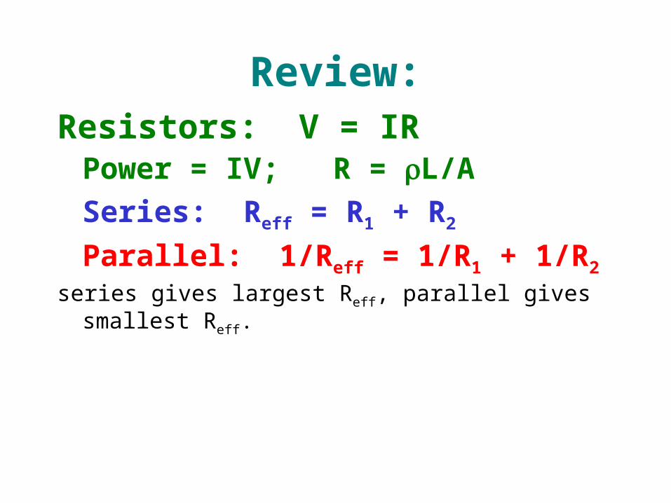
Review:Resistors: V = IR
Power = IV; R = L/A
Series: Reff = R1 + R2
Parallel: 1/Reff = 1/R1 + 1/R2
series gives largest Reff, parallel gives smallest Reff.
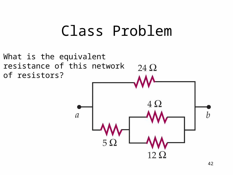
Class Problem
42
What is the equivalentresistance of this networkof resistors?
Capacitance
A water tower holds water. A capacitor holds charge.
The pressure at the base of the water tower depends on the height (and hence the amount) of the water. The voltage across a capacitor depends on the amount of charge held by the capacitor.
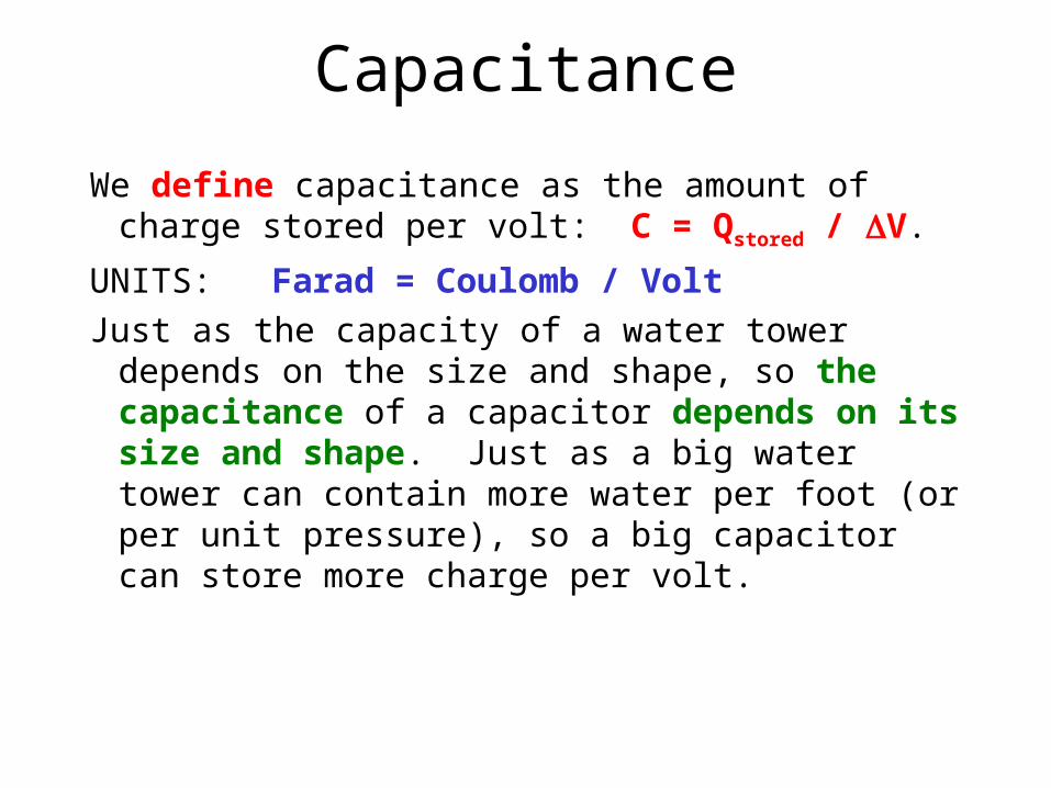
Capacitance
We define capacitance as the amount of charge stored per volt: C = Qstored / V.
UNITS: Farad = Coulomb / Volt
Just as the capacity of a water tower depends on the size and shape, so the capacitance of a capacitor depends on its size and shape. Just as a big water tower can contain more water per foot (or per unit pressure), so a big capacitor can store more charge per volt.
Energy Storage
Note that previously we had:
PE = q*V ,
and now for a capacitor we have:
E = (1/2)*Q*V .
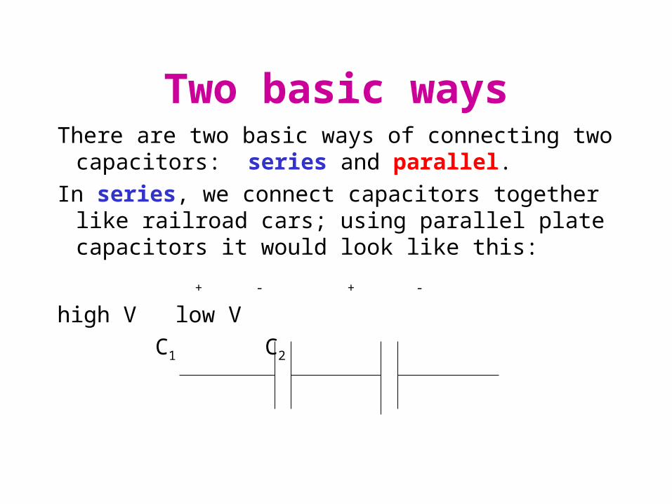
Two basic waysThere are two basic ways of connecting two capacitors:
series and parallel.
In series, we connect capacitors together like railroad cars; using parallel plate capacitors it would look like this:
+ - + -
high V low V
C1 C2
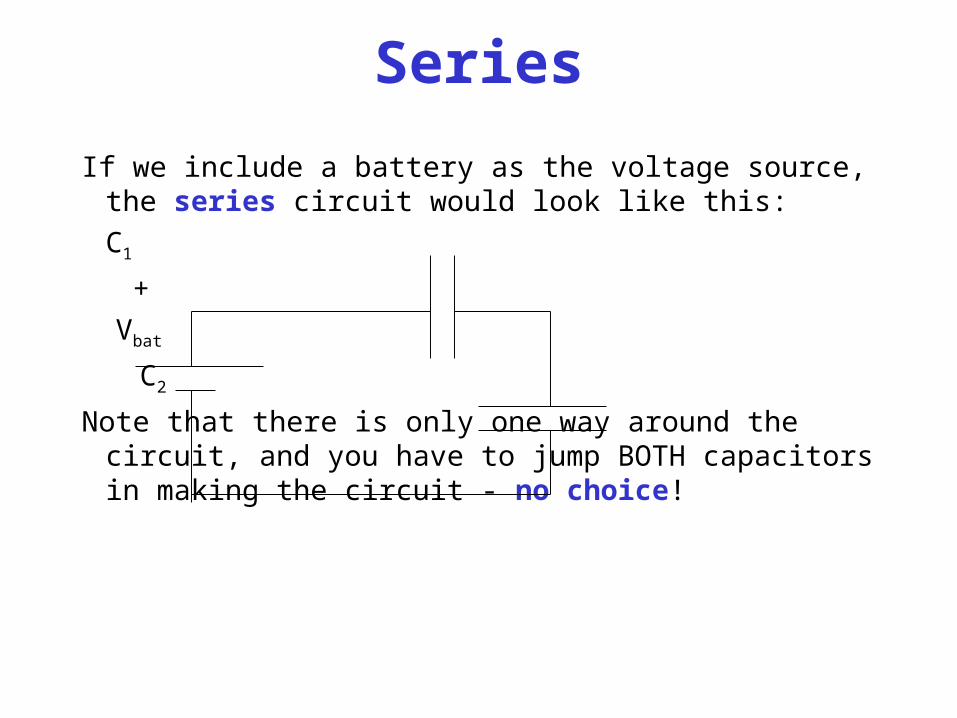
Series
If we include a battery as the voltage source, the series circuit would look like this:
C1
+
Vbat
C2
Note that there is only one way around the circuit, and you have to jump BOTH capacitors in making the circuit - no choice!
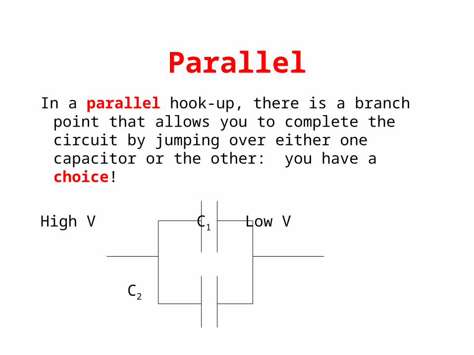
ParallelIn a parallel hook-up, there is a branch point that
allows you to complete the circuit by jumping over either one capacitor or the other: you have a choice!
High V C1 Low V
C2

Parallel Circuit
If we include a battery, the parallel circuit would look like this:
+ + +
Vbat C1 C2
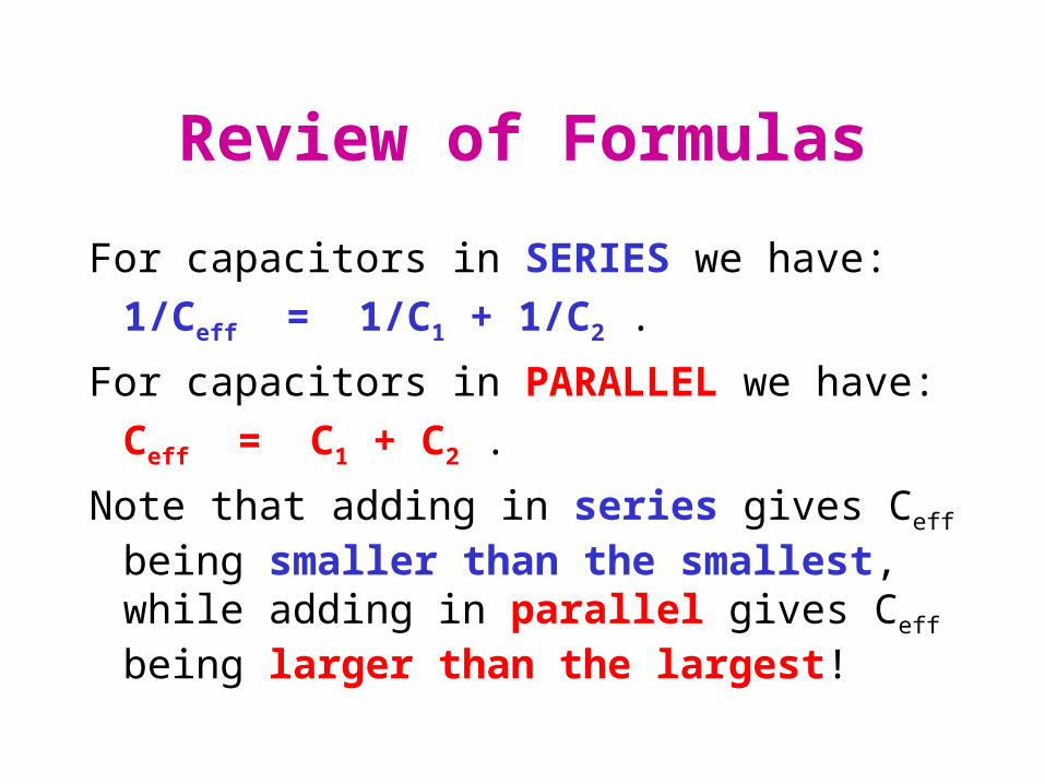
Review of Formulas
For capacitors in SERIES we have:
1/Ceff = 1/C1 + 1/C2 .
For capacitors in PARALLEL we have:
Ceff = C1 + C2 .
Note that adding in series gives Ceff being smaller than the smallest, while adding in parallel gives Ceff being larger than the largest!
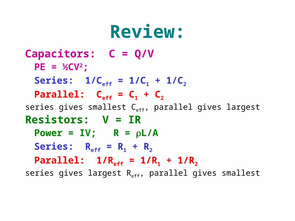
Review:Capacitors: C = Q/V
PE = ½CV2;
Series: 1/Ceff = 1/C1 + 1/C2
Parallel: Ceff = C1 + C2
series gives smallest Ceff, parallel gives largest
Resistors: V = IR Power = IV; R = L/A
Series: Reff = R1 + R2
Parallel: 1/Reff = 1/R1 + 1/R2
series gives largest Reff, parallel gives smallest
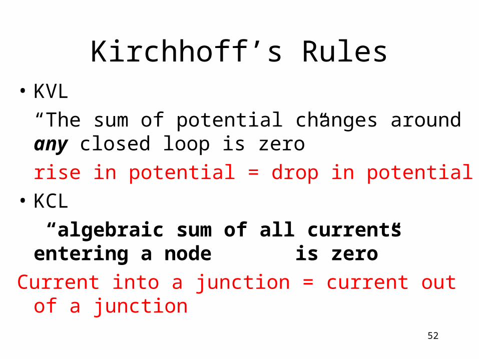
Kirchhoff’s Rules• KVL
“The sum of potential changes around any closed loop is zero”
rise in potential = drop in potential
• KCL
“algebraic sum of all currents entering a node is zero”
Current into a junction = current out of a junction
52
• KCL states that at any node (junction) in a circuit the algebraic sum of currents entering and leaving a node at any instant of time must be equal to zero. Here currents entering(+ve sign) and currents leaving (-ve sign) the node must be assigned opposite algebraic signs.
• KVL states that in a closed circuit, the algebraic sum of all source voltages must be equal to the algebraic sum of all the voltage drops.