electric field propulsion concepts from independent
TRANSCRIPT
theory CHARLES A. YOST
Electric field propulsion concepts from independent researchers
TWENTY-FOUR POSTER PAPERS WERE PRESENTED TO NASA AT THE BREA HROUG PROPULSION PHYSICS WORK-
SHOP. AUGUST 12-14, 1997. ONE PAPER PRESENTED MATERIALS SUBMITIED B
TO THE USE OF INTERACTIVE ELECTRODYNAMIC FIELDS FOR PROPULSIO
ELECTROSTATIC POTENTIAL WAVES WOULD BE GENERATED AND TRA
SURFACE OF ELECTRODES. INTENSE NON-LINEAR POLARIZING WAVES
ROUNDING SPACE, AND IT IS POSSIBLE THAT A PRECISION SYSTEM C
OUS £Sj NETWORKERS PERTAINING
I G TO ONE CONCEPT, PULSED
LO GITUDINAL FORM FROM THE
ER.EBY EXTEND INTO THE SUR-
E 0 OIRECT THEM TO
DEVELOP REACTION FORCES ON SURROUNDING OBJECTS, MEDIA 0 S :ACE E S.
CLASSIC EFFECTS
In the earlier publications of ESJ, much attention was
devoted to investigating T.T. Brown's claims of a connec
tion between electricity and gravity. Experiments
conducted by T.T. Brown indicated that suspended
capacitors underwent linear thrust when a voltage was
applied. (See Fig. 1.) In other experiments, Brown showed
that aluminum saucers, 11/2-2' in diameter, suspended
from tethers on opposite ends of a rotatable bar, would
move rapidly when connected to a 50-15okv source.
(See Fig. 2.) Brown and Bahnson did not establish an
electrogravitics connection, and subsequent testing
of Brown's devices, which tried to eliminate coulomb
forces1 and ion winds, have led to two definitive conclu
sions: (1) The coulomb forces and ion wind were all but
impossible to negate, but when they were nearly elimi
nated, little or no force remained. (2) Transient discharge
of the high voltage terminals resulted in increased thrust levels, indicative of an electrical phenomenon, and not
the electrogravitics interaction that Brown and Bahnson
had sought. Still, the action of intense electric pulsing
continues to be of interest.
ELECTRICAL BEAMS
Schlieren imaging of the region between Wimshurst
electrodes by Yost has shown how electrostatic forces
I Coulom b forces hove been sho wn to be capa ble of levitotmg
small o bjects. (See Figs. 3-5.)
24 Electric Spacecraft Issue 22 Apr/May/jun 1997
alter the density of the surrounding air. Sparks produce
cumuliform pressure bursts from both terminals. When
the negative terminal is fitted with a point or a small
ball, a coherent thread-like stream is emitted. (See Fig. 6.)
A single thread could also be made to emanate from the
positive terminal. but threads from the positive terminal
were substantially weaker than threads with negative
origins. The dual threads do not seem to interact with
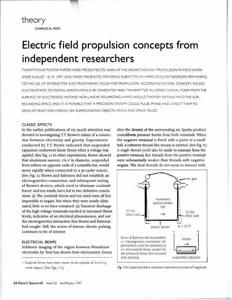
� -orc gop --- �+ I I I I I
movement to ward smaller
rod
• 1/s" dio. 3/s" dio. brass tu be +- brass tu be
�P--"""!"----u , .__ 1 -· plastic spacer L\ = 0.1 0"
motion
+
Brown & Bohnson did not esta blish on electrogravitic connection. All phenomena could be attri buted to ion and coulom b forces, except for the enhanced forces that occurred
with sparking. suspended capacitor
Fig. I Arc pulsed pendulum enhances movement one order of magnitude.

ELECTRIC FIELD PROPULSION CONCEPTS FROM INDEPENDENT RESEARCHERS
rotary saucers 150.000 VDC
Fig. 2 TT Bro wn's Electrogravitic Thruster
Fig. 3 Stationary Levitation
Fig. 4 Mid-or biting Levitation
Fig. 5 High-or biting Levitation
levitated cone
field spread by dielectric shield
HALLfKULBA
each other. Subsequent experiments revealed that the
movement of the thread was not influenced by the
location or movement of the other electrode, ground, or
a neodymium magnet moved in close proximity. A wire
probe connected to a DC microammeter registered a
current of 50 JlA in the stream, and nothing immediately
outside it. A mechanical wind vane, similarly, remained
stationary except in positions intercepting the stream,
where it would spin rapidly. While the stream had
momentum and current, it seemed to be electrically
neutral. It showed slight perturbations when a small
steel ball placed near was suddenly whipped away.
Electrical beams with different properties have been
generated by other means. Morton created a beam by
placing a glass tube having a metal end plate on a
charged Van de Graaff terminal. (See Fig. 7.) He observed
that a spark jumped from the Van de Graaff to the end
plate, which then emitted a beam. The beam charged a
metal target at which it was aimed, as well as every
thing else in its path. Later, based on Morton's observa
tions, Schlecht recreated the phenomenon with a more
sophisticated device at the University Karlsruhe,
Germany. (See Fig. 8.) This pulse device has generated
energy beams which have been able to levitate talcum
powder for brief instances. These beams were accompa
nied by electrostatic field effects and an obvious change
in air pressure noted by experimenters at a distance of
4 m. This beam was not believed to be ion wind because
a neon lamp was 25% ignited and test balls exhibited
slo w-moving convection waves
Fig. 6 A neutral coherent thread, 8"-1 2" long, emitted from
electrode, made visible by schlieren optics
Leicester, North Carolina 28748 USA 25
ELECTRIC FIELD PROPULSION CONCEPTS FROM INDEPENDENT RESEARCHERS
attraction-repulsion behavior when placed in its path,
and its ignition spark was not of the characteristic color
and form of conventional ion propulsion sparks. The
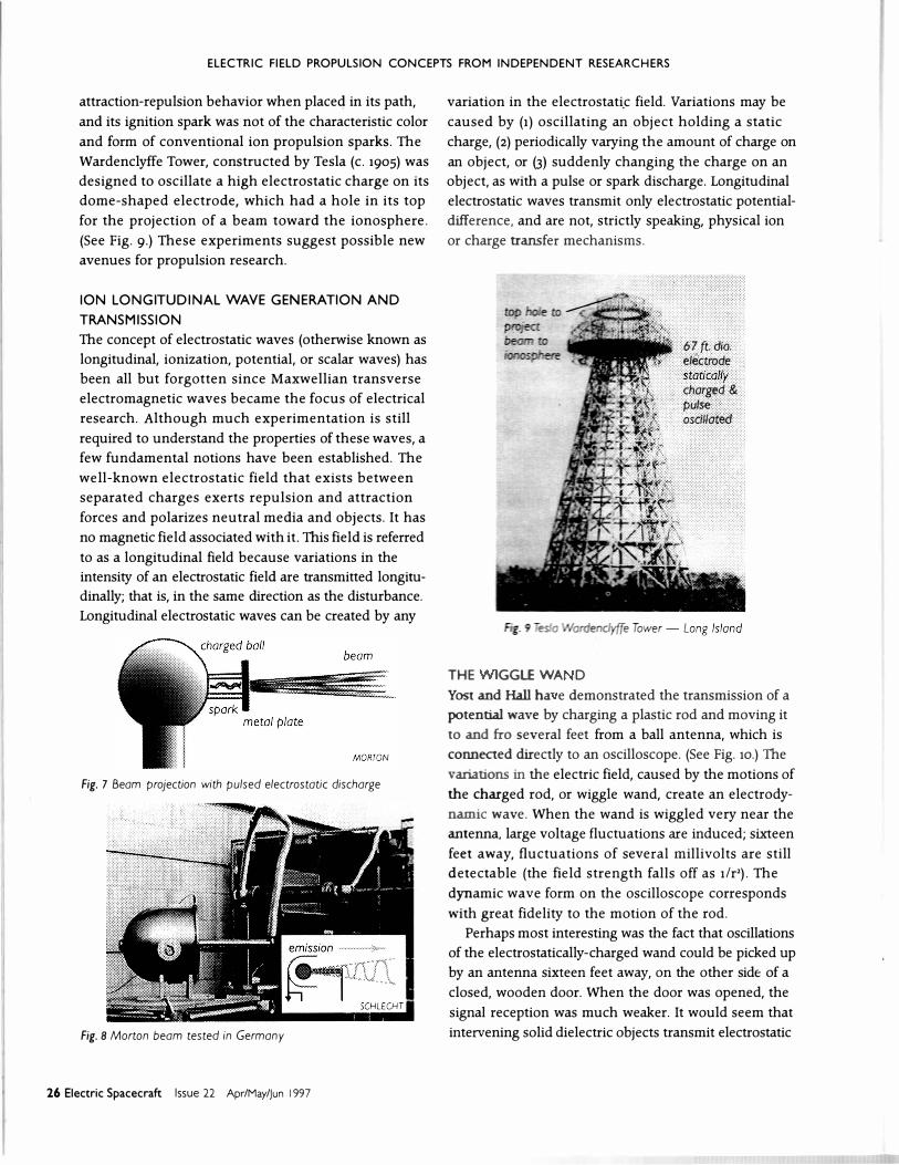
Wardenclyffe Tower, constructed by Tesla (c. 1905) was
designed to oscillate a high electrostatic charge on its
dome-shaped electrode, which had a hole in its top
for the projection of a beam toward the ionosphere.
(See Fig. g.) These experiments suggest possible new
avenues for propulsion research.
ION LONGITUDINAL WAVE GENERATION AND
TRANSMISSION
The concept of electrostatic waves (otherwise known as
longitudinal, ionization, potential, or scalar waves) has
been all but forgotten since Maxwellian transverse
electromagnetic waves became the focus of electrical
research. Although much experimentation is still
required to understand the properties of these waves, a
few fundamental notions have been established. The
well-known electrostatic field that exists between
separated charges exerts repulsion and attraction
forces and polarizes neutral media and objects. It has
no magnetic field associated with it. This field is referred
to as a longitudinal field because variations in the
intensity of an electrostatic field are transmitted longitu
dinally; that is, in the same direction as the disturbance.
Longitudinal electrostatic waves can be created by any
Fig. 7 Beam projection with pulsed electrostatic discharge
Fig. 8 Morton beam tested in Germany
26 Electric Spacecraft Issue 22 Apr/May/jun 1997
variation in the electrostati.c field. Variations may be
caused by (1) oscillating an object holding a static
charge, (2) periodically varying the amount of charge on
an object, or (3) suddenly changing the charge on an
object, as with a pulse or spark discharge. Longitudinal
electrostatic waves transmit only electrostatic potential
difference, and are not, strictly speaking, physical ion
or charge transfer mechanisms.
THE GGL£ WA D
67ft. dia. eliktrode staticallY charged & pulse oscillated
Yost and Hall ha e demonstrated the transmission of a
potential wave by charging a plastic rod and moving it
to and fro several feet from a ball antenna, which is
connected directly to an oscilloscope. (See Fig. 10.) The
variations in the electric field, caused by the motions of
the charged rod, or wiggle wand, create an electrody
namic wave. When the wand is wiggled very near the
antenna, large voltage fluctuations are induced; sixteen
feet away, fluctuations of several millivolts are still
detectable (the field strength falls off as 1/r2). The
dynamic wave form on the oscilloscope corresponds
with great fidelity to the motion of the rod.
Perhaps most interesting was the fact that oscillations
of the electrostatically-charged wand could be picked up
by an antenna sixteen feet away, on the other side of a
closed, wooden door. When the door was opened, the
signal reception was much weaker. It would seem that
intervening solid dielectric objects transmit electrostatic
ELECTRIC FIELD PROPULSION CONCEPTS FROM INDEPENDENT RESEARCHERS
force with less dispersion, just as metal conductors
trartsmit current with very little loss. In air artd vacuum,
the electrostatic force falls off according to the inverse
square law. In solid dielectrics, however, charges polarize,
facilitating the trartsmission of electric fields, much like
conducting materials have been presumed to conduct
electric charge. Deavenport also showed that a light bulb
would oscillate in response to an electrostatic field on
the other side of either a lf4'' thick Plexiglas'" plate, or a
Ifs" thick glass dome.
These experiments support early claims made by Tesla
that electrical energy can be transmitted by means of
longitudinal electrostatic forces, the ground serving as
the current conductor, artd the air acting as a dielectric
for the displacement current. The electrostatic field has
the ability to polarize all atoms (metallic and dielectric).
In the case of conductors, the polarization will cause a
current to flow if the conductive material is in the form
of a closed circuit. Thus, as Tesla suggested, potentials
can be developed as standing waves on the earth, artd
power cart be tapped by putting up a metal antenna.
Electrostatic longitudinal forces are believed to be
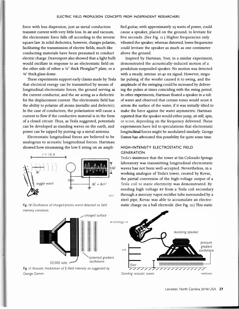
analogous to acoustic longitudinal forces. Hartman
showed how strumming the low E string on an ampli-
r= 1 6ft
Fig. I 0 Oscillations of charged plastic wand detected as field
intensity variations.
/charged surface
YOST
fied guitar, with approximately 25 watts of power, could
cause a speaker, placed on the ground, to levitate for
five seconds. (See Fig. 11.) Higher frequencies only
vibrated the speaker, whereas distorted, lower frequencies
could levitate the speaker as much as one centimeter
above the ground.
Inspired by Hartman, Yost, in a similar experiment,
demonstrated the acoustically-induced motion of a
pendulum-suspended speaker. No motion was detected
with a steady, intense 20-40 Hz signal However, singu
lar pulsing of the woofer caused it to swing, and the
amplirude of the swinging could be increased by deliver
ing the pulses at times coinciding with the swing period.
In other experiments, Hartman floated a speaker in a tub
of water artd observed that certain tones would scoot it
across the surface of the water, if it was initially tilted to
make the force against the water asymmetric. Hartman
reported that the speaker would either jump, sit still, spin,
or scoot, depending on the frequency delivered. These
experiments have led to speculations that electrostatic
longitudinal forces might be modulated similarly. George
Damm has advocated this possibility for quite some time.
HIGH-INTENSITY ELECTROSTATIC FIELD
GENERATION
Tesla's insistence that the tower at his Colorado Springs
laboratory was trartsmitting longitudinal electrostatic
waves has not been well-accepted. Nevertheless, in a
working artalogue of Tesla's tower, created by Kovac,
the partial conversion of the high-voltage output of a
Tesla coil to static electricity was demonstrated. By
sending high voltage RF from a Tesla coil secondary
through a mercury vapor rectifier tube surrounded by a
steel pipe, Kovac was able to accumulate an electro
static charge on a ball electrode. (See Fig. 12.) This static
+-analogy�
50,000 volts
""'potential gradient oscillations
Fig. I I Acoustic modulation of E-field intensity as suggested by
George Damm.
em
Standing acoustic waves
levitating speaker
HARTMAN
Leicester, North Carolina 28748 USA 27

ELECTRIC FIELD PROPULSION CONCEPTS FROM INDEPENDENT RESEARCHERS
field was, in turn, modulated into a waveform, repre
senting the combination of an 8 Hz component and a
wo Hz component, by means of mechanical switches.
The RF rectifier technique allows for higher power
outputs from an electrostatic wave transmitter. This
technique also permits the potential on an antenna to
be modulated, indicating that it might be possible to set
up resonant waves. Timing the electrostatic waves in
a closed system, such as on the earth sphere, allows
transmitted, longitudinal electrostatic polarizations to
be reflected and to return to reinforce the excitation.
Research with Tesla coils has been a constant source
of fascination for experimenters. Hall observed attrac
tive and repulsive responses, for a variety of plastic and
metallic objects suspended near a Tesla coil secondary,
that led him to conclude that the objects were acquiring
a static charge. (See Fig. 13-)
As early as 1991, Hull and his group, known as the
Tesla Coil Builders of Richmond, noticed a buildup and
retention of electrostatic charge on insulated coils and
metallic objects located near an operating Tesla coil.
Controlled experiments were therefore devised by Hull
to quantify the charge buildup on a distant, insulated,
conductive target. Charges of 20 kv were accumulated at
distances up to nine feet away. (See Fig. 14.) Experiments
set up with a fan positioned so as to blow the airborne
charges toward, and then away from, the collector
showed that charging was at least partially due to the
flow of ions, but that perhaps another, faster charging
mechanism was operating as well.
Hull repeated the experiments, replacing the Tesla
coil with a Van de Graaff generator. The instant the Van
de Graaff was turned on, a voltage of 15 kv appeared on
the remote collector. But, it was discovered that in a
steady static field, the collector barely picked up a
charge. It was then supposed that a spark or other rapid
field variation might be responsible for setting up a wave
of charge transmission. Electrical waves propagating
with speeds far in excess of those attainable by ionic
motio1_1s have been researched in-depth. An experiment
in 1930 (Lagarkov and Rutkevich-1993) revealed that a
luminous wave, created by applying 180 kv across a long
vacuum tube at 20 torr, moved with a speed of 5 x 10⁹
cm/s. Because ions cannot move this rapidly, the high
velocity was attributed to the propagation of an electric
potential wave. A Russian patent application by
Avramenko and Avramenko refers to the oscillations of
free charges as the displacement current or longitudinal
28 Electric Spacecraft Issue 22 Apr/May/jun 1997
ft
ft
ft
mercury vapor tu be
strong charge on electroscope
rotary pulse modulator
KOVAC
Fig. 12 Tesla coil RF recti fied to static charge with mercury vapor tu be
·HALL
Fig. 13 Suspended ball s wings and rotates near Tesla coil secondary
1'------- 3 (t - 9 (t ---� meta/ toroid charged to + 20,000 volts
Fig. 1 4 RF arcs electrostatically charge distant conductor
HULL

ELECTRIC FIELD PROPULSION CONCEPTS FROM INDEPENDENT RESEARCHERS
electrical wave, capable of efficiently transmitting power.
Jackson devotes only two sentences in his classic
electrodynamics text to longitudinal electrostatic fields.
Damm has speculated that Tesla incorporated acous
tic resonant criteria in the design and modulation of his
tower at Shoreham, Long Island. The dimensions of the
tower's components and their acoustic resonant frequen
cies are well-matched to the earth's electrical resonant
frequencies. Tesla's notes mention that an electric pulse
would traverse the earth's diameter and return with a
period of 0.08484 seconds. He also claimed that lightning
could resonate the earth electrically. In an investigation
of multiple-stroke lightning, Yost discovered, as Tesla
suggested, that the periods between flashes corre
sponded precisely to simple harmonics of the earth's
diameter; 1/4-, 112-, and %-diameter time periods being
most prevalent. (See Fig. 15.) This suggests that the earth
behaves as a giant dipole antenna, and that the electro
static resonance of the earth was indeed a possibility.
Tesla intended to trartSmit potential differences over the
earth and build them up as resonant standing waves.
__,
5 2 !._4 __
6 7 8 9 10
J.lll�,l1J':l'Y"'J� l-��l�l� Time between strokes
corresponds to earth diameter harmonics. 0 50 100
- time (ms) ---+
Fig. 15 Earth Electrostatic Resonance - Lightning
SPARK DISCHARGES
OGAWA
The spark discharge method of producing pulsed
electrostatic waves is simple, most promising, and little
understood. It is in this pulsed wave form that T.T.
Brown's electrogravitic effects were thought to be
enhanced. Recent developments with spark discharges
have been made possible by engineering advancements
with the Tesla magnifier made by Hull. (See Figs. 16 and
17.) The Tesla magnifier is a third coil, which Tesla used
with some of his traditional coil setups. The magnifier
serves as a free-resonance transformer for creating
extremely high voltages at very low amperages. The
magnifier coil is driven by the Tesla coil secondary. Very
small magnifier coils, on the order of 4" in diameter by
Fig./6 6000 watt Testa magnifier
'/. � :; ceiling suspension
::::
2.5 million volts
42" toroid 9.6' spark
Fig. 1 7 Power input to primary 20kV @ 6kW
HULL
HULL
12" long, are capable of producing to-foot sparks,
without heating or shorting, from a 6ooo watt power
source. Their output consists dominantly of an alternating
electrostatic potential field.
Hull conducted a series of experiments involving the
capacitive loading of Tesla coils. In one experiment, a
coil was loaded until no sparking would occur. When the
coil was turned on, a distant toroid used to collect
electrostatic charge remained electrically neutral, while a
neon tube at the same distance glowed intensely. When
a thumbtack was placed on the terminal of the transmit
ting coil, sparks broke out, the collector toroid registered
an immediate increase in charge, and the neon tube
remained unlit. It became evident that spark discharges
were necessary if the electrostatic transmission effects
were to be observed. It is now believed that the Tesla coil
can serve as a field emitter of pulsed potential to its
surroundings. It is not difficult to produce by this means
megavolts of potential and megawatts of impulse energy.
Further experiments by Hull with capacitive loadings
suggested that capacitive coupling might be occurring.
A coil system was set up so as not to spark. Nearby, a
Leicester, North Carolina 28748 USA 29
ELECTRIC FIELD PROPULSION CONCEPTS FROM INDEPENDENT RESEARCHERS
similarly-loaded, grounded coil, tuned to the frequency
of the transmitting coil, was passively placed as a
receiver and made to produce large sparks. Rotating the
resonator through goa resulted in no change in inten
sity, thereby demonstrating that the sparking was not
due to electromagnetic induction. It was further noticed
that the capacitive loading on the coils had a direct
bearing on the degree of sparking. This indicated that
tuned radio communication was not the sole means of
energy transmission between the coils. In yet another
experiment, two separated, ungrounded, passive,
capacitively-loaded coils were conductively connected
at their bases. (See Fig. 18.) When the active coil was
operated nearby, sparking took place between the passive
coils, which were acting as receivers, and an alternating
current flowed through their connecting base wire. These
phenomena demonstrate a potential for remote charg
ing, which might be applicable to a craft and its
immediate surroundings.
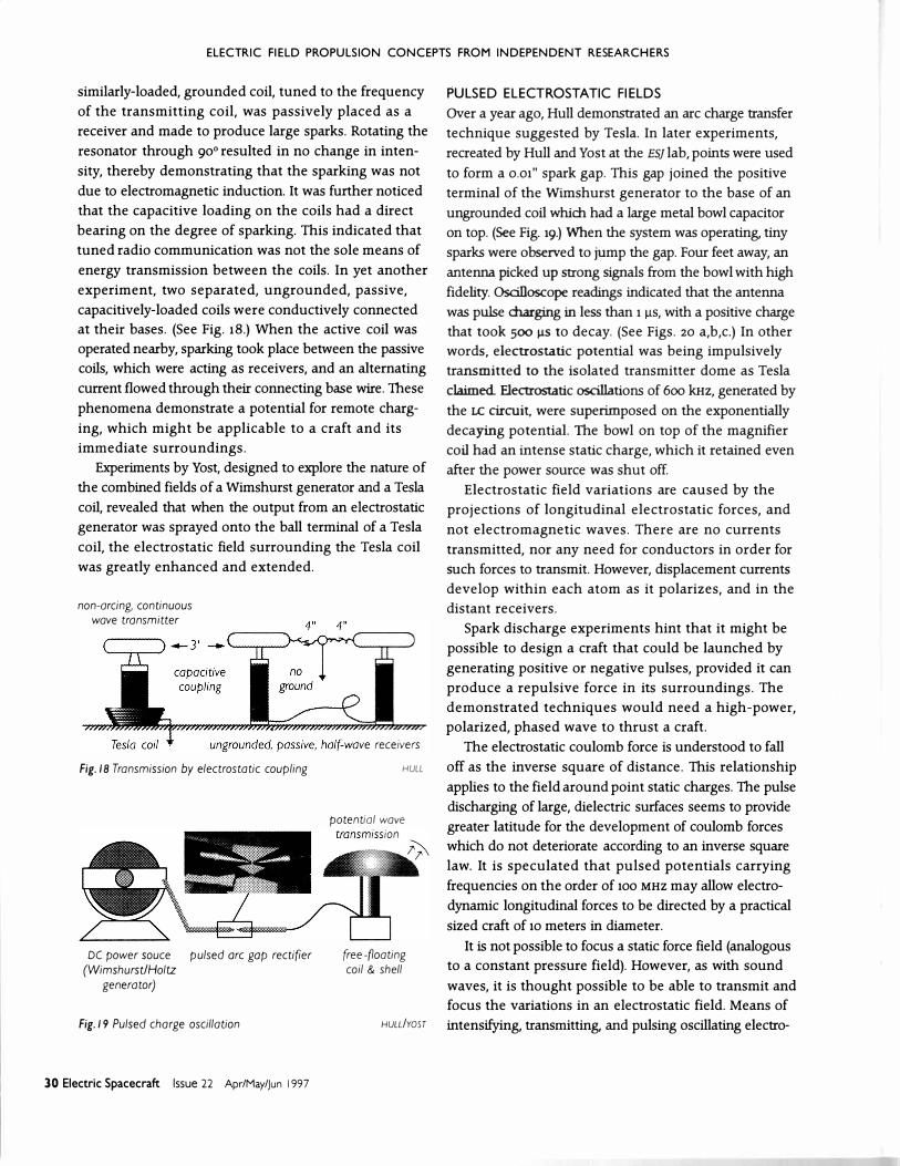
Experinlents by Yost, designed to explore the nature of
the combined fields of a Wimshurst generator and a Tesla
coil, revealed that when the output from an electrostatic
generator was sprayed onto the ball terminal of a Tesla
coil, the electrostatic field surrounding the Tesla coil
was greatly enhanced and extended.
non-arcing, continuous wove transmitter
Fig./8 Transmission by electrostatic coupling
DC po wer sauce pulsed or e gop rectifier (Wimshurst!Holtz
generator)
Fig./9 Pulsed charge oscillation
30 Electric Spacecraft Issue 22 Apr/May/jun 1997
HULL
potential wove
(ree-noating coil & shell
HULL!YOST
PULSED ELECTROSTATIC FIELDS
Over a year ago, Hull demonstrated an arc charge transfer
technique suggested by Tesla. In later experiments,
recreated by Hull and Yost at the ESJ lab, points were used
to form a 0.01" spark gap. This gap joined the positive
terminal of the Wimshurst generator to the base of an
ungrounded coil which had a large metal bowl capacitor
on top. (See Fig. 19.) When the system was operating, tiny
sparks were observed to jump the gap. Four feet away, an
antenna picked up strong signals from the bowl with high
fidelity. Oscilloscope readings indicated that the antenna
was pulse charging in less than 1 J.l.S, with a positive charge
that took 500 J.lS to decay. (See Figs. 20 a,b,c.) In other
words, electrostatic potential was being impulsively
transmitted to the isolated transmitter dome as Tesla
claimed. Flectrostatic oscillations of 6oo kHz, generated by
the LC circuit, were superimposed on the exponentially
decaying potential. The bowl on top of the magnifier
coil had an intense static charge, which it retained even
after the power source was shut off.
Electrostatic field variations are caused by the
projections of longitudinal electrostatic forces, and
not electromagnetic waves. There are no currents
transmitted, nor any need for conductors in order for
such forces to transmit. However, displacement currents
develop within each atom as it polarizes, and in the
distant receivers.
Spark discharge experiments hint that it might be
possible to design a craft that could be launched by
generating positive or negative pulses, provided it can
produce a repulsive force in its surroundings. The
demonstrated techniques would need a high-power,
polarized, phased wave to thrust a craft.
The electrostatic coulomb force is understood to fall
off as the inverse square of distance. This relationship
applies to the field around point static charges. The pulse
discharging of large, dielectric surfaces seems to provide
greater latitude for the development of coulomb forces
which do not deteriorate according to an inverse square
law. It is speculated that pulsed potentials carrying
frequencies on the order of 100 MHZ may allow electro
dynamic longitudinal forces to be directed by a practical
sized craft of 10 meters in diameter.
It is not possible to focus a static force field (analogous
to a constant pressure field). However, as with sound
waves, it is thought possible to be able to transmit and
focus the variations in an electrostatic field. Means of
intensifying, transmitting, and pulsing oscillating electro-
ELECTRIC FIELD PROPULSION CONCEPTS FROM INDEPENDENT RESEARCHERS
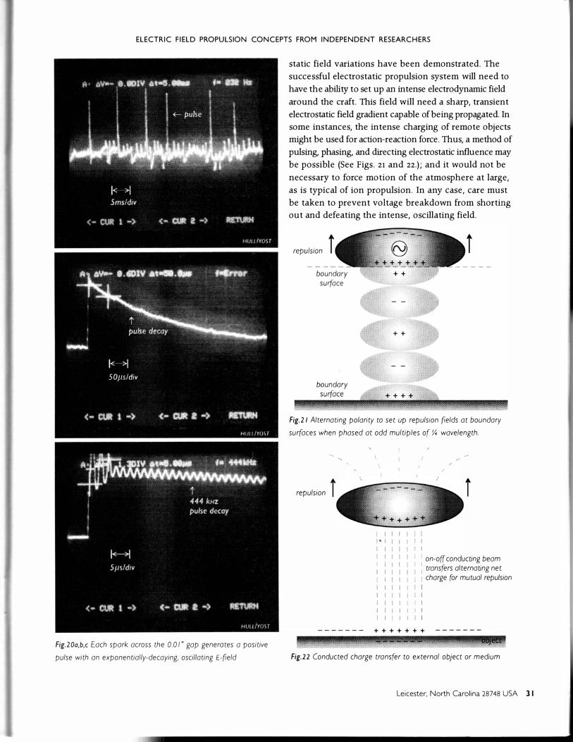
Fig.20a,b,c Each spark across the 0.0 I" gap generates a positive
pulse with an exponentially-decaying, oscillating E-(ield
static field variations have been demonstrated. The
successful electrostatic propulsion system will need to
have the ability to set up an intense electrodynamic field
around the craft. This field will need a sharp, transient
electrostatic field gradient capable of being propagated. In
some instances, the intense charging of remote objects
might be used for action-reaction force. Thus, a method of
pulsing, phasing, and directing electrostatic influence may
be possible (See Figs. 21 and 22.); and it would not be
necessary to force motion of the atmosphere at large,
as is typical of ion propulsion. In any case, care must
be taken to prevent voltage breakdown from shorting
out and defeating the intense, oscillating field.
Fig.21 Alternating polarity to set up repulsion (lelds at boundary
surfaces when phased at odd multiples of Y. wavelength.
'
repulsion i
! I I i-=! I
I I ! I I
i I I I I
! I I ! I I '
I I
! I I I
i
i on-off conducting beam : transfers alternating net i charge for mutual repulsion
+++++++
Fig.22 Conducted charge transfer to external o bject or medium
Leicester, North Carolina 28748 USA 31

ELECTRIC FIELD PROPULSION CONCEPTS FROM INDEPENDENT RESEARCHERS
Aerovironment "Centurion Test Flighf' ESJ 2 I : 36. Alzofon, FE, "Anti-Gravity with Present Technology." I 7th Annual AIAA/SAE/ASME Joint
Propulsion Conference, Colorado Springs, july 27-29, 198 1 I 'The Unity of Nature and the Search for a Unified Reid Theory." Physics Essays, / 99 3, Vol. 6, No.4, pp. 599-6081 'The Origin of the Gravitational Reid," Advances in the Astronautical Sciences 5, NY: Plenum Press, 1960 I 'The Alzofon Popers," ESJ 13:7- 14.
Avromenko, S and Avromenko, K "Longitudinal Electrical Transmission," /nternotiona/ potent application. Moscow 19931 "Russian Potent on: Longitudinal Electrica/Tronsmission," ESJ / 2:20-24
Bohnson,A}r, unpublished lob notebooks I "Electrical Thrust Producing Device," US Potent 3,223,038.
Brown, IT. 'TT Brown Notebooks," partially published by William Moore Publications. no longer available I "How I Control Gravity." Science and Invention Magazine. August /929 I "How I Control Gravity." Anti-Gravity and the Unified Field, ed. DH Childress, / 990, chop. 3 I "Electrostatic Motor." US Potent 1,974,483. 1934 I "Electrokinetic Apparatus," US Potent 2, 949,550 I "Electrokinetic Transducer." US Potent 3,0 18,394 I "Electrokinetic Generator." US Potent 3,022,430 I "Electrokinetic Apparatus," US Potent 3, I 87,206 I ''A Method of and on Apparatus or Machine for Producing Force or Motion," British Patent 300,3 1 1.
Carroll, RL Beyond the Farthest Star, VA Carro// Research Institute I''ESJ Forum," ESJ / 9: I 0-1 I I 'The Photon," ESJ / 9: 14- 15 I 'The Perpetuation of Error." ESJ 2 I: 14- 1 B.
Corum,}, " I 00 Years of Cavity Resonator Development" 1990 Teslo Symposium, ITS I Corum, J and Corum, K, "A Physical Interpretation of the Colorado Springs Data," 1984 Teslo Symposium, ITS I "Reproducing Colorado Springs Coi/,"TCBA News, vo/. 7, no. 21 'Technical Analysis of Extra Coil as a Slow Wove Helical Resonator." 1986 Tes/o Symposium, ITS I 'Teslo Coil - An RF Power Processing Tutorial for Engineers," 1988 Teslo Symposium, ITS I 'Transmission Theory." TCBA
News, vol. 8, no. 41 Corum, K, "Concerning Cav•ty Q," / 988Teslo Symposium, ITS I ''A Rediscovery ofTeslo's RFTechniques," / 990 Teslo Symposium, ITS.
Cox,} E. "Dipolar Force Field Propulsion System," US Pacem #4,663, 9 32 I "Dipole Accelerating Means & Method," US Potent #4,89 1,600 I 'Toroidal Spark Gap Engine," ESJ 5:6- / 0 I "Dipolar Force Reid Propulsion System," ESJ 5, I 1- 1 3 I "Shuttle Propulsion Using Eleccromognedc Force Fields," AIAA 17th Joint Propulsion Conference, Colorado Springs, CO July 27-29, 198 I I 'The Space Drive Handbook." Pomona, CA 196 1 I 'Toroidal Spark Gop Engine Tests," ESJ / /:26-29.
Damm, GW. 'The Teslo Longitudinal Wave," ESJ / 5:23-26. Deovenport. L. 'TT Brown Experiment Replicated." ESJ 16:34-36 I"E/ectroscoeic ion Thrust
Experiments," ESJ / 7:7-9 I "Dielectric Field Force," ESJ 2 / :32. Froning. HD & Barrett, TW, "Inertia Reduction - and Possibly Impulsion - by Conditianmg
Electromagnetic Fields," 33ndAIAA/ASMEISAEIASEEJoint Propulsion Conference & Exhib•t Seattle, july 6-9, 1997.
Groneou, P, "Electro/Magnetic Jet-Propulsion in the Direction of Current Flow." Nature, vol. 295,Jonuory 28, / 9821 Ampere-Neumann Electrodynamics of Metal� Nonantum, MA Hodronic Press, 1985 I "Estimating the Strength of Water Arc Explosions," Galilean
Electrodynamics 2, no. I ,jon/Feb 199 / I 'The Anomalous Strength o(Wocer-Piosmo Explosf()(lS. •
The MIT Cold Fusion Symposium, jon. 2 I , / 99 5 I Letter co the editor. ESJ I 7:5 I Azevedo, R Groneou, P, and Millet C, "Powerful Water Plasma Explosions," Physics Letters A July 28, 1986 I Groneou, P; Pappas, PT; Ruscok,lj; & Swollom, DW. "Electrodynamic Water Arc Gun.· The 4th Symposium on Electromagnetic Launch Technology. University ofTexos. Apri( 1988 I Groneou, P, & Graneou, N. Newton versus Einstein, NY: Carlton Press, / 99 3 I Newtonian
Electrodynamic� River Edge, NJ:World Scientific Publishing. 1996. Hall, RS, 'Tes/o Coil Electric Field T hrust Experiments," ESJ 5:2 /-25 I "Morph•ng the
Electrostatic Generator for Flight and Other Experiments," ESJ / 6:20-23 I "E/eccrosraoc Transmission in Air." ESJ / 7: I 0- 13 I 'The Electrokinetic Works o(TT Brown," ESJ I :6- 1 1.1 Hal( RS and Kulbo, LA "Eieccroscadc Experiments," ESJ I 8:2 1-26.
Hortman,}, "Field Resonance Concept" ESJ 5:36 I "Acoustic Radiation Test Usmg an Electric Guitar." ESJ 6:4 3-44 I "Levitating Electromagnetic Spheres," ESJ 8:40-4 I I "Gwcor Thruster." ESJ / 7:25.
Hathaway, GD, PhD, 'T he Hutchison Effect" ESJ 4:6- / 2 I laboratory notes & Vfdeo documentation I Letter co the editor. ESJ 6:7 I 'The Hutchison Effect - A Life and DISrupuve System," Proceedings of the 3rd New Energy Technology Symposium. A Michrowsi<J. ed Ontario: Planetary Association (or Clean Energy. I 988.
Hull, R laboratory notes & video documentation I "Activity Update," ESJ 6:2 I "Activity Update," ESJ 8:4 I 'Tes/o Coils and Electrostatics," ESJ 9:7- 13 I 'Tes/a Magnifier Basics," ESJ 10:7- 121 "New Innovations from Lose or Abandoned Technology." ESJ / / : 13-34 I'Woter Arc Exp/osions," ESJ 14:7- 151 'Water Arc Experiments," ESJ / 5:371 'TCBOR Transmissions," ESJ 17: 6 I 'Teslo Coils, Electric Gradients and Electrostatics," ESJ I 8:27-3 1 I ''ESJ Forum," ESJ / 9: I 3 I "Electrostatics and its Measurement" ESJ 20: 8- 14.
32 Electric Spacecraft Issue 22 Apr/May/jun 1997
Hutchison,}, "Hutchison Lab Serup. • ESj 7:43 I 'The Hutchison Effect Apparatus," ESJ 9:2 / -28. JePmenko, OD, Causality. Electromagnetic Induction and Gravitation, ScarOty. WV: Electret
Scientific Co., 1992 (esp. p. 28) I Lecrer to the editor. ESJ /7:51 Electricity and Magnetism. Scar City. WV: Electret Scienofic Co. 1989 I''E.Sj Forum." ESJ / 9: 9.1 Electromagnetic Retardation
and Theory of Relativity. Star 0ty. WV:Eleccret Soenufic Co., / 997. Jero/e, LF. "Migrating Soap Bubbl� • ESj /9:29. Kovac, R 'The Power Wave (1899-1991)". ESj 3:6- /71 "Electrostatic Life Experiments,"ESJ
5: 14-20 I Private lob notebooks I and I. December /990 co May 199 1 I "Plasma Shaping: An Atomic Transmutation Concept"ESJ 14·16-23.
Kulbo, LA "c=(c,p,)"." ESj 18:6-121 Brown's Rock Electricity." ESJ 20:2 / -25. Lororkov, AN & Rudcrvich, 1M. lonu:a on Waves in Electrical Breakdown of Gase�
NY: Springer-Verlag. 199 3 LaViolette, PA. PhD. �� Bode o the Future." ESJ 4:23-28 I "A Theory of
Eleccrogravrucs," ESJ 8:33-361" 1-'anemode Power Supply (or Electrogrovitics," ESJ 8:37-39 I "A Tesla Wave Physa foro Fre! £nerw lhverse. "I 990 lncemationo/Teslo Society Conference, Colorado Springs, CO I� US Squadron," Electrogravitics Systems, Integrity Res. /nst. 1994.
Lee. TP, "Ofi Fi Ex ESJ 22:25.
ts. • ESI I 29-30 I"E/ectrostotico//y Charging Powders,"
Morton, a "Morton's Spoao o.-_· ESj 4 35-38
Moers, II< "Arlop. ·US l I 990 I " ovel A•rship Design," ESJ 9:34-35 I
"EJ�wed Orowo.T. book of Atmospherics, Vol. I , Boca Raton:
CRC Pre.s:s. I 9 0/uess, EC � Vehode." US Potent #3,464.207. Overbey, RG. "()..ebey Mas:e-'s 1heszs on Brown's Electrokinetics." ESJ 16:38. Ph#s, TE. �Venoes: Mathemaucal Themes in Physical Description, Urbano, /L :
OOSSICOI Non-&Jnn � I 8 I "ESS Forum," ESJ /9:9- / 0. Schlecht. /( Taley. RL � Cenrury Propulsion Concept" /, II, and Ill prepared for Philips
l..oborotay.Ar fctce � Command Propulsion Directorate, Edwards AFB, CA 9 35 2 3 with Vencay edvJolow. he.. PO Box 305, East Amherst NY 1405 I, April 1998, September 1988, and May I
Tesla, Colorado Spnngs ot� 1899- 1900. Prepared for publication by the Nikolo eslo MusaJm &ogrodYugosJOVfO: No/it / 978 I Nikola Tesla-Lectures. Patents, Article�
pref)<nd and pdJiished by the Nikolo Tesla Museum, Beograd. Yugoslavia, No/it / 956, pp. L-68-1..-091 Complete Patents Mil/brae. CA:Teslo Book Company. 1983, p. 4321 Nikola Tesla
on His with Alternating Currents and Their Application to Wireless Telegraphy.
T� & T ranstrission of Power, ed. by Leland Anderson, Denver: Sun Publishing of Denver. I 991 I The lr?.oentions. Researches and Writings of Nikola Tesla Martin Lindsay. pub. 1988 I Tesla: Lecture before the New York Academy of Science� Leland Anderson, ed., 8recketv>oge. CO 21st Century Books. 1994.
�. T. ed. Electnogravitics Systems: Reports on a New Propulsion Methodology,
�DC: Integrity Research /nsticute I 'TT Brown's Electrogravitics," ESJ / 4:24-29. v.blcemon,A. 'Toroidal Vortex Flow." ESJ 3:45 I "Energy Synthesis," ESJ 2 / :6- / 3. Wolton, G. ed. Special Relativity Letter, Nos. 1-3. Whittaker, ET. "On the Partial Differentia/ Equations of Machemocicol Physics," thematische Annalen. 57. 1903:333-55 I"On an Expression of the Electromagnetic Reid
Due ID Electrons by Means of Two Scalar Potential Functions," Proceedings of the London Mathemaocol Society. I, 2nd se<, 1904:367-72.
Yost, CA "High Voltage Concentric Reid Generator Design," lncernoeional Teslo Symposium, /990 I''Eiectroscodc Concentric Field Generator Experiments,"ESJ I :27-331 "Roller Magnets," ESj I :371"/on-Propelled Ring Ship,"ESJ I :42 I 'TT Brown and the Bohnson Lob Experiments,"ESJ 2:f>.12I"Con Hoc Surfaces Be Cooled E/ectrico//y."ESJ 2:25-261 "Electric Propulsion Research," ESj 3:37-39 I"Osci//oscope-E/ectric Field Measurement During Nearby Tomado,"ESJ 5:43-44. I "Electrostatic Longitudinal Waves," ESJ 8:7- 13 I "Possibilities of Electric Field Propulsion," proceedings of the /ntemotiono/ Symposium on New Energy. Denver: April / 6- / 8, 199 3 I "Auc/io Speaker Thrust" ESJ 8:40 I "Speculations Related co Electric Reid Propulsion," ESJ I 0:25-32 I'T he Seccorless Wimshursc Electrostatic Generator." ESJ I I : 15- 1 8 I "On the Nature ofRelds," ESJ / 1:331 "Longitudinal ElectroclynomicWave Experiments,"ESJ 12: I 8- 191/aborocory notes & video documentation I "Coherent T hreadlike Emission Discovered," ESJ / 6:6 I "Electrostatic Force Flow Visualization," ESJ / 6:7- / 9 I 'T Townsend Brown Notebooks," ESJ 18: 13- 17 I "Electrostatic Force Experiments," ESJ I 8:32-37.
Note: A paper by F. Znidorsik was provided by NASA as a handout

CHARLES A. YOST Electric Spacecraft, Inc. 322 Sunlight Drive Leicester, NC 28748
Electric weather Forces
Tel: 828-683-0313 828-683-2617
Fu: 828-683-3511 E-m• II: [email protected] Website:
In spite of Earth's immense size, lightning signature data is shown"
to have voltage pulses at periods coincident with harmonics of
Earth's diameter. This suggests that the earth behaves like a giant
dipole antenna. Nikola Tesla concluded this from his studies of
lightning electrical wave nodes at Colorado Springs in 1899.
Nikola Tesla proposed to transmit electrical power over the entire Earth without wires. This proposal was based on his belief that the entire Earth could be electrically resonated. The primary purpose of this report is to examine Tesla's concept of Earth electrical resonance, the ramifications of which would lead to an entirely new understanding of global weather forces.
BACKGROUND
When Nikola Tesla proposed that lightning was an earth resonance phenomenon, he also stated that the resonance would occur at wavelengths corresponding to 1,4 and other odd quarter multiples of the earth's diameter, such as%, 5/4, etc. This report presents the results of lightning signature data analysis designed to test these considerations. In addition, it draws attention to certain implications Earth electrical resonance may have for global weather.
The measurements of time intervals between the distinct flashes and pulse periods of lightning wave traces seem to indicate the presence of wavelengths corresponding to Earth electrical resonance. The evidence appears in both photographic and electrical measurements of time periods. Thus, some types of lightning appear to operate in accordance with resonance conditions associated with the earth's dimensions. The existence of multiple stroke lightning could therefore be explained by electric fields beyond the clouds themselves; fields of a global nature.
It is worth noting that the fundamental 0.08484 sec period, as quoted by Tesla, is the time it would take light to travel through the earth's diameter and reflect back. This clearly suggests that he thought electrical impulses could travel direccly through the earth. This was and still is looked upon as rather incredible and unlikely; but certainly is a possibility.
If we assume, as shown in Figure 1 , an electric pulse to expand radially in all directions, it would travel both the surface and the diameter distances in the same time. We see the surface distance to be 1t/z times further. As a result, the surface velocity would appear to be 7t/z times faster than the speed of light, or 47 1 ,240 km/sec, which is what Tesla said.
(surface distance/ t) (2 x diameter/ t)
(1rDit) _" 2Dit -2
The natural condition of Earth electrical resonance caused by lightning would indicate that man-made Earth resonance could also be imposed using the techniques developed b Tesla. While the part electricity plays in forming our global weather has not been used in forecasting, irs dfecr is becoming increasingly evident from the continued research results of many space scientists. One is led to consider the real possibilities of weather modification b the imposition of electrical forces.
Lighming is a common event, but still a mystery in the decli.ls o irs production. In 1 899 Tesla performed experiments to produce lightning effects of an earth scale and claimed ro have succeeded. Even today, 1 00 years after Teslas experimentation, there are skeptics who question his claim abouc Earth elecuical resonance, mainly because of their focus on the predictions of Maxwell's electromagnetic wave theory. flecuostatic impulse, polarization waves and the properties of electrostatic/ electrodynamic impulses raise
questions not presently answered by Maxwellian theory.
TESLA'S PATENT #787,412
Tesla srated the basic requirement for Earth resonance in his Parent"' 8 ,4 1 2, filed May 1 6, 1 900, and issued on April 18, 1905 (Tesla 1 905) . The patent states in part:
... The planer behaves like a perfectly smooth, polished conducror of inappreciable resistance with capacity and self-induction uniformly disuibuted along the axis of symmetry of wave propagation and aansmining slow electrical oscillations without sensible distortion and attenuation.
. .. Three requirements seem to be essential to the establishment of the resonating condition.
Fmr. The Earth's diameter passing through the pole should be an odd multiple of the quarter wavelength; that is, of the ratio between the velocity of light and four times the frequency of the currents.
Second. It is necessary to employ oscillations in which the rate of radiation of energy into space in the form of hertzian or electro mag-
Leicester, North Carolina 287 48 USA 11
netic waves is very small . . . I would say, that the frequency should be smaller than rwenty thousand per second . . .
Third. The most essential requirement is, however, that irrespective of frequency, the wave or wave train should continue for a certain interval of time, which I have estimated to be not less than one-rwelfth or probably 0.08484 of a second and which is taken in passing to and returning from the region diametrically opposite the pole over the earth's surface with a mean velocity of about four hundred and seventy-one thousand rwo hundred and forty (47 1 ,240) kilometers per second.
TH E E LECTRIC WAVE
Little is said about properties of a purely electric wave. Nevertheless, some thoughts are herein entertained about the nature of the electric wave. Scientific nomenclature is often vague about making a distinction between electric waves, electrodynamic waves and electromagnetic waves. The waves we are considering are not electromagnetic, since such waves are not likely to travel through the earth, and do not transmit currents. Tesla was also definite about this point.
The electric wave would need to have predominantly longitudinal electrostatic properties, and is essentially a force and a polarization wave. An electrostatic field intensity can change with very little magnetic induction, since there is no
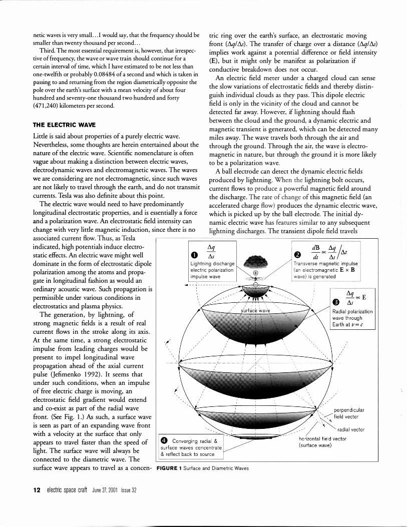
tric ring over the earth's surface, an electrostatic moving front (D.ql D.s) . The transfer of charge over a distance (D.ql D.s) implies work against a potential difference or field intensity (E) , but it might only be manifest as polarization if conductive breakdown does not occur.
An electric field meter under a charged cloud can sense the slow variations of electrostatic fields and thereby distinguish individual clouds as they pass. This dipole electric field is only in the vicinity of the cloud and cannot be detected far away. However, if lightning should flash between the cloud and the ground, a dynamic electric and magnetic transient is generated, which can be detected many miles away. The wave travels both through the air and through the ground. Through the air, the wave is electromagnetic in nature, but through the ground it is more likely to be a polarization wave.
A ball electrode can detect the dynamic electric fields produced by lightning. When the lightning bolt occurs, current flows to produce a powerful magnetic field around the discharge. The rate of change of this magnetic field (an accelerated charge flow) produces the dynamic electric wave, which is picked up by the ball electrode. The initial dynamic electric wave has features similar to any subsequent lightning discharges. The transient dipole field travels
associated current flow. Thus, as Tesla �----;:::============;---------=================�-� indicated, high potentials induce electrostatic effects. An electric wave might well dominate in the form of electrostatic dipole polarization among the atoms and propagate in longitudinal fashion as would an ordinary acoustic wave. Such propagation is permissible under various conditions in electrostatics and plasma physics.
The generation, by lightning, of strong magnetic fields is a result of real current flows in the stroke along its axis. At the same time, a strong electrostatic impulse from leading charges would be present to impel longitudinal wave propagation ahead of the axial current pulse Qefimenko 1 992) . It seems that under such conditions, when an impulse of free electric charge is moving, an electrostatic field gradient would extend and co-exist as part of the radial wave front. (See Fig. 1 .) As such, a surface wave is seen as part of an expanding wave front with a velocity at the surface that only appears to travel faster than the speed of light. The surface wave will always be connected to the diametric wave. The
0 Lig htn i ng d i scharge e lectr ic po lar izat ion impu lse wave
surface wave appears to travel as a concen- FIG U R E 1 Surface and D iametr ic Waves
1 2 e lectric space craft J une 27, 2001 Issue 32

The Earth po la r reg ion 20 kV-80 kV
mag netic po le
i onosphere p lasma 50- 1 50 km th ick conductive layer with strong e lectr ic cu rrents in var ied patterns acts as a buffer s h ie ld
da i ly revo l ut ion of ax is �w orb it p lasmapause f ie ld & Earth f ield merge at po les � tropopause (th i n dark l i n e)
�· 0- 1 2 km th ick � - go% of atmosphere conta i ns
- wh ite band �. al l observed c louds & weather ..-/ 20-40 km th ick , <» ..-/
co ld , d ry, cond uctive \ /. i nteractive reg ion
eo.:.:,�\ol
-------------- ·� ........--- \
FIG U R E 2 The Ionosphere and Tropopause
through all forms of media and is portrayed to be independent of the traveling electromagnetic field radiated.
Tesla indicated that these high potential waves would reflect from the anti-pole. Near perfect conductivity can be achieved by a polarization wave, whether it is carried by a dielectric or a metal conductor, since there is no current flow associated with polarization. This is like the "displacement current" of a capacitor as defined by Maxwell.
The polarization wave is a result of an electrostatic field intensity E (volts/meter) being suddenly imposed, varied or discharged. If no electric charge is transferred between atoms in the process, no current is generated between atoms. Nevertheless, an electric wave transient - a polarization wave - will propagate. This is particularly true of good insulators since the electrons will not transfer. On the other hand, polarization waves will even pass through metals, which shift electrons easily. An ungrounded metal will not stop polarization waves from passing through. A polarization wave will pass through anything . . . metals, insulators, air, plasma, wood - anything; but metals can be used to redirect the path of a polarization wave to ground. The concept of ground becomes less meaningful when talking about the whole Earth as the conductor, or an otherwise solitary electrical system.
Theoretically, the polarization wave can even pass through the earth's diameter. The polarization wave is confined to the earth body and projected radially from the E-field source. Thus, an electric field pulse intensity (E) will diminish as its front widens, and then begin to increase again as the front approaches the pole opposite its origin. If there were no losses , the E-field would return to its original source intensity, by reflection. Tesla said that it took 250 h .p . to overcome the losses while traveling the earth, which he attributed to water evaporation as the wave passed over the surface!
ec l i pt ic
WAVE D ETECTION
Two kinds of lightning data were obtained and analyzed in search of Earth electrical resonance.
1 . Time-based photographs of multiple-stroke lightning flashes, and
2. Oscilloscope recordings of electrodynamic potential pulses generated by lightning.
If Earth resonance exists, it should show in photographs as
specific time intervals between flashes; and it should show in voltage signatures as regular time intervals between sudden impulses on wave features. The time intervals sought would be determined by the dimensions of the earth and the speed at which potential waves travel. By hypothesis, we assume a wave to travel the surface of the earth and through the earth's diameter. The electrical wave is presumed to travel at the speed of light.
A signal propagated through the earth's diameter and back again to the point of the initial lightning would determine a fundamental radial wave period. For harmonics, this diametric wave could be divided into lA, Y2,% or other time intervals. The times defined by the radial wave periods can then be compared to the measurements taken from lightning photographs and voltage signature data.
Tesla's objective at Colorado Springs was to verify that the earth could be electrically resonated. He did not strive to produce arcs of lightning. (Nonetheless , his experiments are remembered for their awesome lightning displays; and, ironically, the primary effort of most Tesla coil enthusiasts today is to see how big they can make the spark.) Tesla continued his Colorado Springs experiments in order to determine how to prevent the sparks since they represented a breakdown in the electric fields he was trying to control . He concluded his investigation with the impression that he had indeed learned how to control the wild spark.
Leicester, North Carolina 28748 USA 1 3

travel d i stance travel t ime reflection travel d i stance travel t ime reflection Returning to New York, Tesla
started to build his new design for Earth electrical resonance: the Wardenclyffe Tower on Long Island. It was different from any of his previous designs, and papers from the archives of Leland Anderson have only recently revealed some of his methods (ES] 26: 5- 1 0) . Part of the reason I went to Belgrade in 1 978 was to search for some answers about the specifics of the Wardenclyffe
(d iameter u n its) i nterval (sec) frequency (Hz) (c ircumference un its) interval (sec) frequency (Hz)
5 D 0.2 1 25 4 D 0. 1 700 3 D 0. 1 275 2 D 0.0850 7/4 D 0.0744 312 D 0.0637 5/4 D 0.053 1 1 D 0.0425 3/4 D 0.03 1 9 1 /2 D 0.02 1 2 1 /4 D 0.0 1 06 1 /8 D 0.0053 1 / 1 6 D 0.0026
design. The Corum's have done TAB LE 1 The L ig ht-Tim e Tab le
likewise a number of times . The half circle pictured in Figure 2 represents the earth. The
line making this circle represents the atmosphere, but it is drawn three times too thick for the scale of the drawing. On this small scale, the storm clouds are buried in the hairline thickness of the atmosphere. As you can see, the earth's atmosphere is very thin, and it would be easily dominated by the electrical forces of space that surround it. Such electrical forces are naturally imposed by electrical charge emissions from the Sun and the earth's magnetic field which traps these charges in its magnetosphere. Electric forces surrounding the earth could be the cause of global atmospheric high and low pressure systems. But even today, pressure systems are only measured and reported to describe the weather. When the pressures change it is without any explanation!
LIG HT·TI M E PERIODS The time intervals that should exist for specific harmonics of the earth's diameter can be calculated. Measurements of the lightning waveform pulses should show distinct features at these calculated time intervals.
In the computation of a fundamental Earth electrical period: 1 . The Earth's diameter is given as 1 2 ,742 km, and 2. The speed of light (c) is given as 299,792 km/sec.
The fundamental time interval for a wave to independently travel twice the earth's diameter at light speed c is :
tv = 2D = 2 X 12,742 km 0.0850 sec ( 1 1 .76 Hz) . c 299,792 km/sec
This is very close to the 0.08484-second value suggested by Tesla, and represents nearly l/12 of a second.
The fundamental time interval for an electric wave to independently travel via the earth's surface (S) to the anti-pole and return when moving at the speed of light is:
t = tcD = tc X l 2,742 km = 0. 1 335 sec = (7.49 Hz) . 5 c 299,792 km/sec
14 e lectric space craft June 27. 2001 Issue 32
4.7 1 4 s 0.5340 1 .87 5.88 3 s 0.4005 2.49 7.84 2 s 0.2670 3.74
1 1 .76 1 s 0. 1 335 7.49 1 3.44 7/8 s 0. 1 1 68 8.56 1 5.70 3/4 s 0. 1 000 9.99 1 8.83 5/8 s 0.0834 1 1 .98 23.53 1 /2 s 0.0667 1 4.98 3 1 .35 3/8 s 0.0500 1 9.97 47. 1 7 1 /4 s 0.0333 29.96 94.34 1 /8 s 0.0 1 67 59.9 1
1 88.68 1 / 1 6 s 0.0083 1 1 9.8 384.6 1 1 /32 s 0.00 4 1 239.6
The light-time table is a list of the fundamental and harmonic periods for electromagnetic radiation travelling the diameter and circumference of the earth. (See Table 1 . ) The time values are based on the average Earth diameter. The equivalent number of reflections per second (frequency) is listed next to each light-time period. Surface waves are notable in that there appears to be a near 60 cycle per second harmonic at VsS. Other integer harmonics appear likely at %S ( 1 0 Hz) , %S ( 1 2 Hz) , Y2S ( 1 5 Hz) , %S (20 Hz) , 'AS (30 Hz) , and l/ t 6S ( 1 20 Hz) .
A comparison of diametric periods and circumferential periods does not show any exact matches. However, a few compared periods are close:
2D @ 0.0850 sec compares to %S @ 0 .0834 sec; the difference is 0 .00 1 6 sec.
%D @ 0.03 1 9 sec compares to 'AS @ 0.0333 sec; the difference is 0 .00 1 4 sec.
These time differences, while only differing by about one thousandth of a second, represent light travel distances of about 250 miles . Thus, it does not appear that independent circumference and diameter waves could reinforce each other. The possibility of some phase reinforcement exists within the 250-mile regions, though. Higher wave harmonics could make the time differences smaller.
Surface wave periods and harmonics did not correlate well with the data measured and are therefore not discussed further in this report.
DATA COLLECTION AN D M EASU R E M E NT Except for the literature references cited, the data used in this report comes from storms I recorded in the Asheville, North Carolina area (Yost 1 985) . The specific lab site and antenna are shown in Figure 3. Initially, in 1 983, the antenna signals were
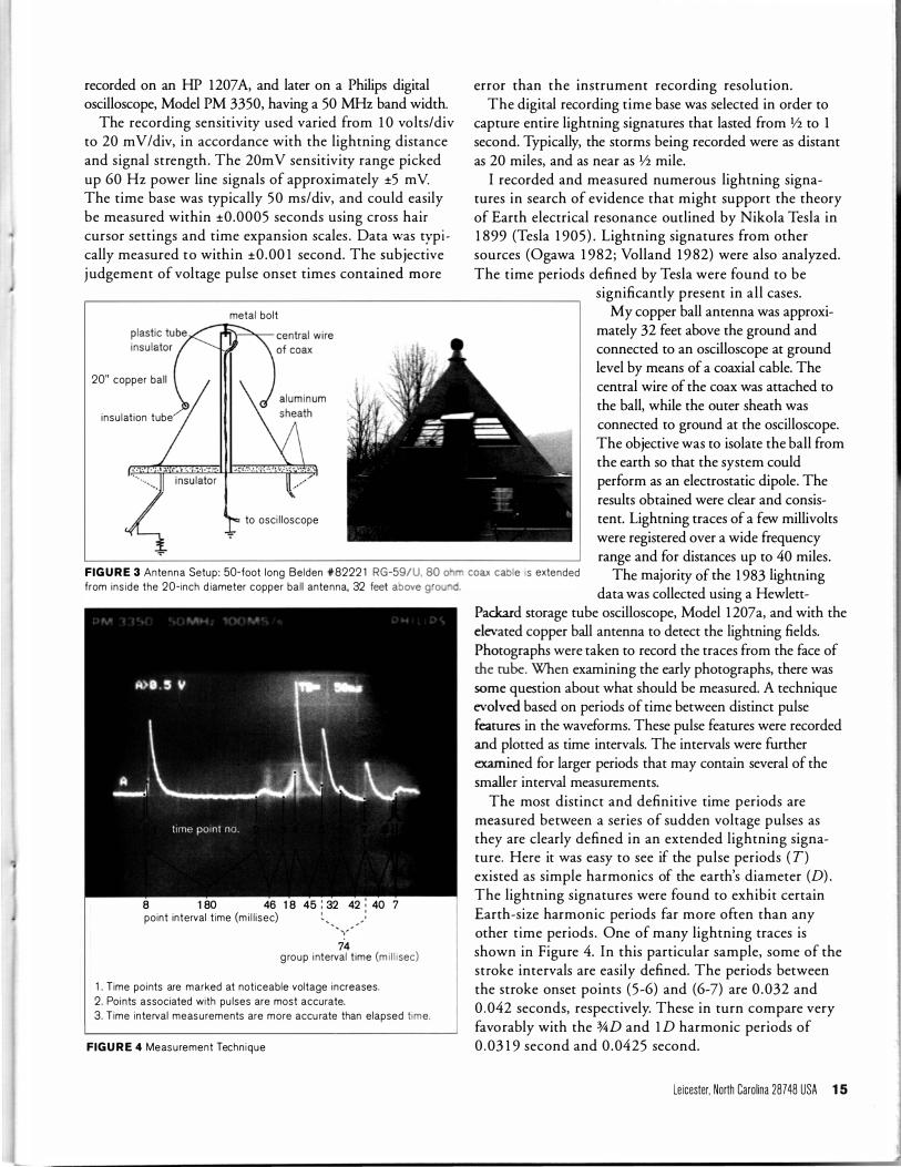
recorded on an HP 1207 A, and later on a Philips digital oscilloscope, Model PM 3350, having a 50 MHz band width.
The recording sensitivity used varied from 1 0 volts/div to 20 mV/div, in accordance with the lightning distance and signal strength . The 20m V sensitivity range picked up 60 Hz power line signals of approximately ±5 m V. The time base was typically 50 ms/div, and could easily be measured within ±0 .0005 seconds using cross hair cursor settings and time expansion scales . Data was typ i cally measured to within ±0 .00 1 second. The subjective j udgement of voltage pulse onset times contained more
metal bo l t
20" copper ba l l
i n su lat ion tube
to osc i l l oscope
FIG U R E 3 Antenna Setup : 50-foot long Be lden 4F8222 1 RG-59/U, 80 o from i ns i de the 20- inch d iameter copper ba l l antenna, 32 feet above g o
8 1 80 46 1 8 45 : 32 42 : 40 7 po int interval t ime (m i l l i sec) •
74 g roup i nterval t ime (m i l l i sec)
1 . T ime po i nts are marked at not iceable voltage i ncreases. 2 . Po i nts associated with pu lses are most accu rate. 3 . T ime i n te rval meas u rements are more accu rate than e lapsed time.
FIG U R E 4 Meas u rement Techn i que
error than the instrument recording resolution. The digital recording time base was selected in order to
capture entire lightning signatures that lasted from Y2 to 1 second. Typically, the storms being recorded were as distant as 20 miles, and as near as Y2 mile.
I recorded and measured numerous lightning signatures in search of evidence that might support the theory of Earth electrical resonance outlined by Nikola Tesla in 1 899 (Tesla 1 905) . Lightning signatures from other sources (Ogawa 1 982 ; Volland 1 9 82) were also analyzed. The time periods defined by Tesla were found to be
significantly present in all cases. My copper ball antenna was approxi
mately 32 feet above the ground and connected to an oscilloscope at ground level by means of a coaxial cable. The central wire of the coax was attached to the ball, while the outer sheath was connected to ground at the oscilloscope. The objective was to isolate the ball from the earth so that the system could perform as an electrostatic dipole. The results obtained were clear and consistent. Lightning traces of a few millivolts were registered over a wide frequency range and for distances up to 40 miles.
coax cable is extended The majority of the 1 983 lightning data was collected using a Hewlett
Packard storage tube oscilloscope, Model 1 207a, and with the elevated copper ball antenna to detect the lightning fields. Photographs were taken to record the traces from the face of the tube . When examining the early photographs, there was some question about what should be measured. A technique evolved based on periods of time between distinct pulse features in the waveforms. These pulse features were recorded and plotted as time intervals. The intervals were further examined for larger periods that may contain several of the smaller interval measurements.
The most distinct and definitive time periods are measured between a series of sudden voltage pulses as they are clearly defined in an extended lightning signature. Here it was easy to see if the pulse periods ( T) existed as simple harmonics of the earth's diameter (D) . The lightning signatures were found to exhibit certain Earth-size harmonic periods far more often than any other time periods . One of many lightning traces is shown in Figure 4. In this particular sample, some of the stroke intervals are easily defined. The periods between the stroke onset points (5-6) and (6-7) are 0 .032 and 0 .042 seconds, respectively. These in turn compare very favorably with the %D and 1 D harmonic periods of 0 . 03 1 9 second and 0 .0425 second.
Leicester. North Carolina 287 48 USA 15

The earth can have many harmonics, not only from its diametric size, but also from multiple storm harmonics and from internal cloud lightning activity. The premise in this study is that resonant periods are most likely to show as time intervals between distinct pulses on the trace.
It is evident from the compiled data that the most frequent resonant period is at V4D with frequent periods also at 3/sD, 5/sD, %D, '1/sD and 1 V4D. The great majority of time intervals fall within a one-Earth diameter period, with periods beyond 2D fairly well distributed at V4D unit intervals. The extension of intervals beyond 2D that fall on V4D unit intervals would support the idea of Earth resonance at odd multiples of the V4 wavelength as Tesla suggested.
The data presented suggests that Earth electrical resonance is a function of its diameter. Some data scatter and the inability to clearly resolve 1/J GD harmonics has prevented an examination of surface wave periods or possible combinations of surface wave and diameter wave beat periods.
All of the data in the original 1 983 repott is collected and
resonant period (earth d ia.)
0
1D
2D
num ber of occurrences
• ••••••• •• •••• ••••••••• •••• •••••• •••••••••• ••••• ••• •••••••••• •• •• ••• •• • ••••• • •• •
•
••
presented in the Summary of Data chatt shown in Figure 5 . This chatt shows a dot for
Ogawa· Type Trace
Time
each time interval measured from the voltage traces. The time intervals are scattered, but can be seen to predominate at Earth diameter harmonic periods. Since the data is displayed in terms of the earth diameter, contributions from other factors are not defined. Other factors that could scatter harmonics include ionospheric irregularities, induction effects or other storm system interactions.
OGAWA DATA
An independent lightning signature (Volland 1 982, 1 8 1 ; Howener & Bradley 1 964, 1 1 5 5) provides data on a multiple-stroke flash recorded at frequencies of 5 kHz, 1 0 kHz, 45 kHz, and 1 1 MHz. Two strokes are clearly evident and separated by 0 .074 seconds, which coincides with the 1 % Earth diameter period. (A measurement error of perhaps ±0.00 1 seconds may exist in this case.)
Another excellent lightning signature from Ogawa ( 1 982) was measured for time period data. This lightning signature was recorded with fast and slow antennas, and is illustrated in Figure 6.
The measurements of time intervals from this 1 0-stroke flash are shown in Table 2, and demonstrate frequent Y2D and %D harmonic values. The data correlate very favorably with Earth diameter harmonics .
s low antenna
• • FIG U R E 6 Ogawa L ightn ing S ignature 3D
• • • t (sec)
tlt measu red point (sec)
• to 0 --
tl 0.022 0.022 4D • tz 0.043 0.02 1
t3 0.064 0.02 1 t4 0.096 0.032
• t5 0. 1 25 0.029 t6 0. 1 95 0.070 t7 0.230 0.035 t8 0.263 0.033 5D t9 0.3 0 1 0.038
FIGURE 5 Summary of Data TAB LE 2 Ogawa S ignature Data
1 6 electric space craft June 27. 2001 Issue 32
d iameter d iameter per iod error (sec) error (%)
harmon ic nD t = nD/c -- -- -- -
V2D 0.02 1 0.00 1 5 V2D 0.02 1 0 0 V2D 0.0 2 1 0 0 3f4D 0.032 0 0 3f4D 0.032 0.003 9 1 3f4D 0.074 0.004 5 3f4D 0.032 0.003 9 3f4D 0.032 0.00 1 3
3f4 to 1 D 0.032 to 0.042 -0.006 to 0.004 -
I
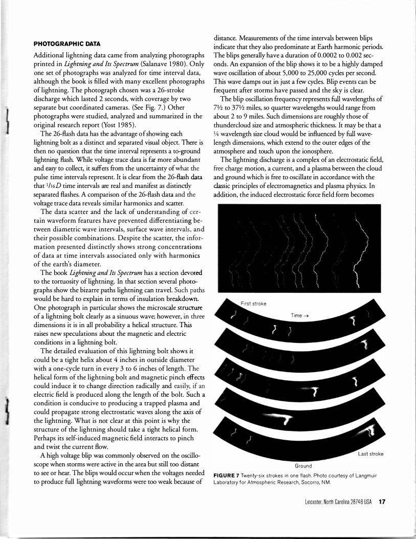
PHOTOG RAPH I C DATA Additional lightning data came from analyzing photographs printed in Lightning and Its Spectrum (Salanave 1 980) . Only one set of photographs was analyzed for time interval data, although the book is filled with many excellent photographs of lightning. The photograph chosen was a 26-stroke discharge which lasted 2 seconds, with coverage by two separate but coordinated cameras . (See Fig. 7.) Other photographs were studied, analyzed and summarized in the original research report (Yost 1 985 ) .
The 26-flash data has the advantage of showing each lightning bolt as a distinct and separated visual object. There is then no question that the time interval represents a to-ground lightning flash. While voltage trace data is far more abundant and easy to collect, it suffers from the uncertainty of what the pulse time intervals represent. It is clear from the 26-flash data that 1h6D time intervals are real and manifest as distinctly separated flashes. A comparison of the 26-flash data and the voltage trace data reveals similar harmonics and scaner.
The data scatter and the lack of understanding of certain waveform features have prevented differentiating between diametric wave intervals, surface wave intervals, md their possible combinations. Despite the scatter, the information presented distinctly shows strong concentrations of data at time intervals associated only with harmonics of the earth's diameter.
The book Lightning and Its Spectrum has a section devoted to the tortuosity of lightning. In that section several photographs show the bizarre paths lightning can travel. Such paths would be hard to explain in terms of insulation breakdown. One photograph in particular shows the microscale suucrure of a lightning bolt clearly as a sinuous wave; however, in three dimensions it is in all probability a helical structure. This raises new speculations about the magnetic and electric conditions in a lightning bolt.
The detailed evaluation of this lightning bolt shows it could be a tight helix about 4 inches in outside diameter with a one-cycle turn in every 3 to 6 inches of length. The helical form of the lightning bolt and magnetic pinch effects could induce it to change direction radically and easily, if an electric field is produced along the length of the bolt. Such a condition is conducive to producing a trapped plasma and could propagate strong electrostatic waves along the axis of the lightning. What is not clear at this point is why the structure of the lightning should take a tight helical form. Perhaps its self-induced magnetic field interacts to pinch and twist the current flow.
A high voltage blip was commonly observed on the oscilloscope when storms were active in the area but still too distant to see or hear. The blips would occur when the voltages needed to produce full lightning waveforms were too weak because of
----- - -- -
distance. Measurements of the time intervals between blips indicate that they also predominate at Earth harmonic periods. The blips generally have a duration of 0.0002 to 0.002 seconds. An expansion of the blip shows it to be a highly damped wave oscillation of about 5,000 to 25 ,000 cycles per second. This wave damps out in just a few cycles. Blip events can be frequent after storms have passed and the sky is clear.
The blip oscillation frequency represents full wavelengths of ?Y2 to 37Y2 miles, so quarter wavelengths would range from about 2 to 9 miles. Such dimensions are roughly those of thundercloud size and atmospheric thickness. It may be that a \.4 wavelength size cloud would be influenced by full wavelength dimensions, which extend to the outer edges of the atmosphere and touch upon the ionosphere.
The lightning discharge is a complex of an electrostatic field, free charge motion, a current, and a plasma between the cloud and ground which is free to oscillate in accordance with the classic principles of electromagnetics and plasma physics. In addition, the induced electrostatic force field form becomes
G round
FIG U R E 7 Twenty-s ix strokes i n one f lash . Photo courtesy of Langm u i r Laboratory f o r Atmospheric Research, Soco rro, N M .
Leicester, North Carolina 287 4 8 USA 17
very prominent (Jefimenko 1 992) . Some indication of the unique behavior of plasma can be gained from the book Plasma: The Fourth State of Matter (Frank-Kamenetskii 1 972) . The section of that text entitled "Electrostatic Plasma Oscillations and Plasma Oscillations in a Magnetic Field" can be particularly related to the phenomena of lightning. FrankKamenetskii relates that electrostatic plasma oscillations exist which are longitudinal (acoustic) and that these oscillations should not be confused with the transverse electric waves asso
ciated with the electromagnetic wave. Surface standing waves may occur should there be a resonant cavity relationship with the dimensions of the column that contains the plasma.
An electrostatic wave traveling through the earth's diameter at the speed of light may have an associated phase wave traveling faster than light at its intersection with the surface, as Tesla indicated. Since the test data indicates the predominance of lightning time intervals at Earth diameter harmonics and not circumferential or Schumann waves, a much closer study seems justified. Expanded study would explore the manner of possible wave propagation through the eanh and the character of sharp electrostatic gradient waves.
ANOMALOUS PH ENOM E NA
While lightning signatures were the focus of the research, other phenomena were also recorded. Two incidents are worth mentioning, even though they were somewhat anomalous.
( 1 ) May 5, 1 992: (recorded with a Philips PM3350 scope mounted in my automobile. I was parked during a storm a few miles outside Champaign, Illinois . ) A tornado was in the area. The scope was recording lightning signatures normally. During a quiet period, the scope suddenly traced a series of large-amplitude, undulating, irregularly shaped sine waves. These continued for several seconds before the scope trace returned to normal. The phenomenon happened briefly again a few minutes later. The irregular sine wave had a frequency of about 2 Hz.
18 e lectric space craft June 27. 2001 Issue 32
(2) At 3 :00 A . M . , my North Carolina lab site recorded 1 5 Hz sine waves with a 2-second (amplitude modulated) beat frequency. The storm being monitored had passed and it became too distant to record lightning signatures .
REFERE NCES Fran k-Kamenetsk i i , D. A 1 972. Plasma: the fourth state of matter. Trans lated
from Russ ian by Joseph Norwood, J r. New York: P lenum Press. Howener and Brad ley. 1 964. Journal of A tmosphere and Terrestrial Physics
26: 1 1 55. lmyan itov, I . M . and E. V. Chubarina 1 965. E lectric ity of the free atmosphere.
Trans lated from Russian for NASA by Is rael Program for Scientif ic Trans lat ions, Ltd . Jerusalem.
Jef imenko, Oleg D. 1 992. Causa l ity, e lectromagnet ic i nduction and g ravitat ion . Star C i ty, WV: E lectret Scientif ic Com pany, p . 27.
Kato, Susumu . 1 980. Dynamics of the upper atmosphere. Boston , MA: D. Re ide l Pub l i sh i ng Co.
Ogawa, Tos h io . 1 982. The l ightn ing cu rrent. Handbook of A tmospherics
1 : 3 1 . Boca Raton , FL : CRC Press. Popovic, Horvat and Noko l ic. 1 956. N i ko la Tes la, 1 856- 1 943. Beog rad,
Yugos lav ia : N i ko la Tes la M useum. Ratzlaff, John T., comp. 1 980. Dr. N i ko la Tes la, se lected patent wrappers.
C h u la Vista, CA: Tes la Book Co. Salanave, Leon E. 1 980. L ightn ing and its s pectrum . Tucson : The U n iversity
of Arizona Press. Sk i l l i ng , H u g h H. 1 960. Fundamentals of e lectric waves. 2d ed, 9th pr int ing .
New York : John Wi ley & Sons , I nc. , 1 942. Tesla , N i kola . 1 905. Art of transm itt ing electr ical energy through the natural
med ium . U.S. Patent >lf787,4 1 2, Apr i l 1 8. Fi led May 1 6, 1 900. --. 1 978. N i ko la Tes la Co lorado Spr ings notes 1 899- 1 900. Beog rad,
Yugos lavia: Nol it Pub l . Vol land , Hans. 1 982. Low frequency rad io no ise . Handbook of Atmospherics
1 : 1 8 1 . Boca Raton , FL: CRC Press. Webb, Wi l l i s L. 1 980. Geoelectr ic ity. Persona l Pu b l ication . E l Paso :
U n ivers ity of Texas at E l Paso. Yost, Charles A 1 985. E lectric weather forces : a Tes la v is ion . Proceedings
of the Testa Centennial Symposium. Colorado Spr ings , CO: I nternational Tes la Society, I nc., pp . 77-88.
--. 1 992. E lectr ical forces app l ied to bas ic weather phenomena. Proceedings of the FAA lntl A erospace and Ground Conference on
Lightning and Static Electricity. Atlant ic C ity, NJ : Federal Aviat ion Admin istrat ion , pp . 5- 1 to 5- 1 0.