electric fireplace insert - ghp group inc. led firebox...electric fireplace insert model #23 ......
TRANSCRIPT

1
ELECTRIC FIREPLACEINSERT
MODEL #23-700-712
Questions, problems, missing parts? Before returning to your retailer, call our customerservice department at 1-877-447-4768, 8:30 a.m. – 4:30 pm CST, Monday – Friday.
��������������
INSTALLER: Leave this manual with the appliance.CONSUMER: Retain this manual for future reference.
WARNING!IF THE INFORMATION IN THIS MANUAL IS NOT FOLLOWED EXACTLY,
AN ELECTRICAL SHOCK OR FIRE MAY RESULTCAUSING PROPERTY DAMAGE, PERSONAL INJURY OR LOSS OF LIFE.
IMPORTANT INSTRUCTIONSPLEASE READ THIS MANUAL BEFORE INSTALLING AND USING APPLIANCE
Français p. 19
Español p. 39
ATTACH YOUR RECEIPT HERE
Serial Number ________________________________ Purchase Date _________________________________
20-10-123
™

2
IMPORTANT: Read all instructions and warnings carefully before starting installation. Failure to follow these instructions may result in a possible electric shock, injury to ������������ ��������������������������
Please read the Installation & Operating Instructions before using this appliance.
TABLE OF CONTENTS
Safety Information ............................................................................................................................ 3
Package Contents ............................................................................................................................ 6
Preparation ....................................................................................................................................... 8
Installation Instructions ..................................................................................................................... 9
Operating Instructions .................................................................................................................... 11
Care and Maintenance ................................................................................................................... 13
Electric Wiring Diagram .................................................................................................................. 14
Troubleshooting .............................................................................................................................. 15
Warranty ......................................................................................................................................... 16
Replacement Parts ......................................................................................................................... 17

3
Please read and understand this entire manual before attempting to assemble, operate or install the product.
1. Read all instructions before using this appliance.
2. This appliance is hot when in use. To avoid burns, do not let bare skin touch hot surfaces. If provided, use handles when moving this appliance. Keep combustible materials, such as furniture, pillows, bedding, papers, clothes and curtains at least 3 ft. (914 mm) from the front of this appliance.
3. CAUTION: Extreme caution is necessary when any heater is used by or near children or invalids and whenever the heater is left operating unattended.
4. If possible always unplug this appliance when not in use.
5. Do not operate any heater with a damaged cord or plug or after the appliance malfunctions, has been dropped or damaged in any manner.
��� �������� ������� �������� �������������������������������� ������ ���
��� �������������� ���� � ��������� ���������������������� �����������������������servicing must be replaced prior to operating this appliance again.
8. Do not use outdoors.
9. This heater is not intended for use in bathrooms, laundry areas and similar indoor locations.Never place this appliance where it may fall into a bathtub or other water container.
10. Do not run cord under carpeting. Do not cover cord with throw rugs, runners or the like. �������������������������������� ��������������������������������
11. To disconnect this appliance, turn controls to the off position, then remove plug from outlet.
12. Connect to properly grounded outlets only.
13. This appliance, when installed must be electrically grounded in accordance with local codes, with the current CSA C22.1 Canadian Electrical codes or for USA installations, follow local codes and the National Electric Code, ANSI/NFPA No. 70.
14. Do not insert or allow foreign objects to enter any ventilation or exhaust opening as this may ��� ����������� ���!"��������������������������
$%�� &�������� ������"������������!���������! ����'��� ����������������*������� ���� ����surfaces, like a bed, where openings may become blocked.
16. This appliance has hot and arcing or sparking parts inside. Do not use it in areas where �� ����"���������+������������� ����� ����� ������&�� �������� ������������� ��� � a drying rack for clothing, nor should Christmas stockings or decorations be hung on or near it.
17. Use this appliance only as described in this manual. Any other use not recommended by the ������������������� ���"�������� ���!������;�������� �� �
18. Avoid the use of an extension cord because of the risk of overheating the cord and the risk �������<'�� �������� ����������������� �������=�����'�� ����������� ����� �"���� �� �����>?@G��������"���������$%��H$J�%QV"�$X%Y���'����������$Z��Q[��������� and constructed of two current carrying conductors with ground. A heavy duty extension cord with the shortest length possible for the connection is recommended and must not be longer than 50 ft. (15.2 m). Do not coil or cover the extension cord.
SAFETY INFORMATION SAVE THESE INSTRUCTIONS
4
GROUNDING PIN
METAL SCREW
GROUNDING MEANS
COVER OF GROUNDEDOUTLET BOX
ADAPTER
(A)
(B)
(C)
(D)
GROUNDINGPIN
SAFETY INFORMATION
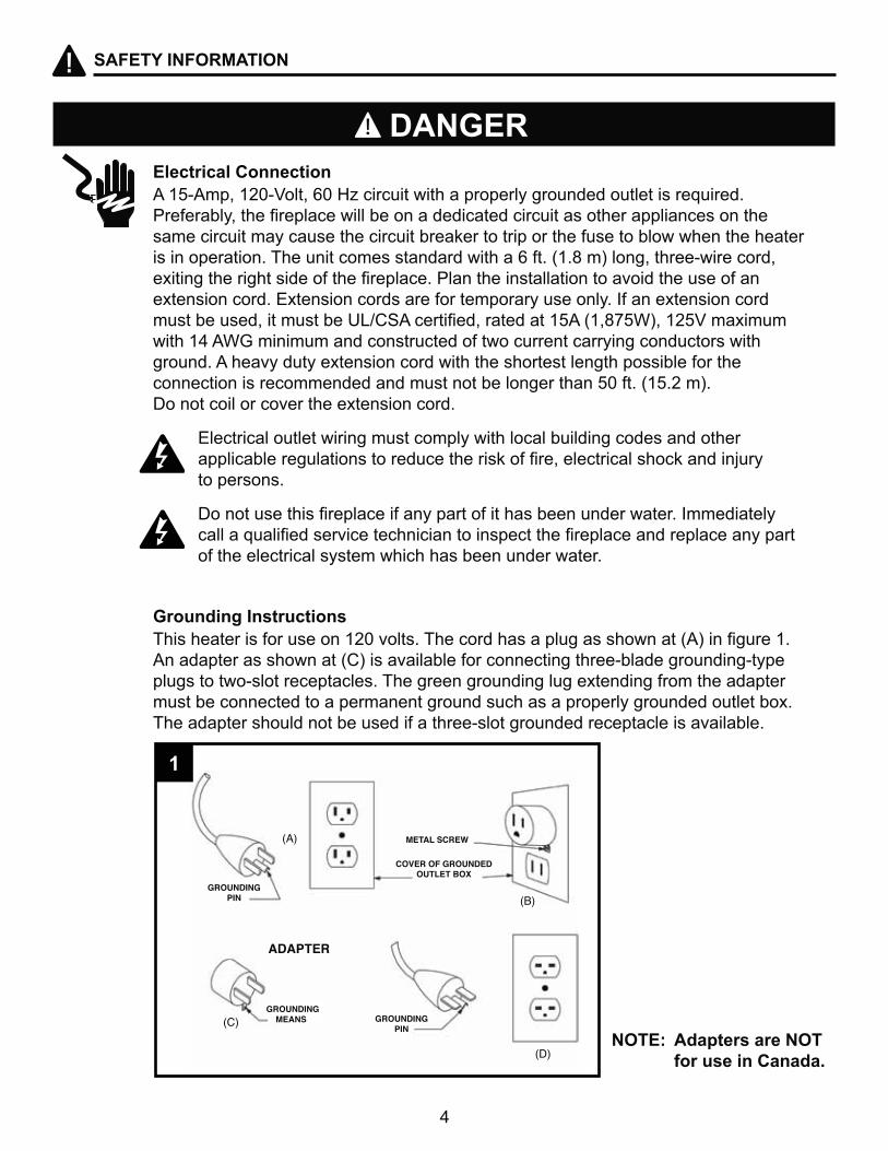
Electrical Connection
Grounding Instructions
��$%\��"�$X]\Y���"��]�^_������������������������������������� ��������� ��������"��������������������������������������� ������������ ������� same circuit may cause the circuit breaker to trip or the fuse to blow when the heater is in operation. The unit comes standard with a 6 ft. (1.8 m) long, three-wire cord, '��������������� �������������������������� ����������������������� ������� extension cord. Extension cords are for temporary use only. If an extension cord �� ����� �"������ �����>?@G��������"���������$%��H$"J�%QV"�$X%Y���'����� �����$Z��Q[���������������� ��������������������������������������� ������ground. A heavy duty extension cord with the shortest length possible for the connection is recommended and must not be longer than 50 ft. (15.2 m). Do not coil or cover the extension cord.
Electrical outlet wiring must comply with local building codes and other ����������������� �������������� !������"���������� ���!�������;���� to persons.
*������� ���� �������������������������� ���������������=��������� ��������������� �������������������� ����������������������������� of the electrical system which has been under water.
&�� ������� ������ ����$X]����� ��&��������� �������� � ��������H�V���������$��An adapter as shown at (C) is available for connecting three-blade grounding-type plugs to two-slot receptacles. The green grounding lug extending from the adapter must be connected to a permanent ground such as a properly grounded outlet box. The adapter should not be used if a three-slot grounded receptacle is available.
NOTE: Adapters are NOT for use in Canada.
DANGER
1
5
SAFETY INFORMATION
Remote Control
ELECTRICAL, PLUMBING OR GAS LINES MAY BE IN WALL.Before cutting, drilling or hammering verify their location. If needed, contact your electrician, plumber or service person.
PRODUCT DAMAGE MAY OCCUR. Never attempt to disassemble or alter the product in any way not instructed by this manual.
This device complies with Part 15 of the FCC Rules. Operation is subject to the following two conditions: (1) this device may not cause harmful interference, and (2) this device must accept any interference received, including interference that may cause undesired operation. This equipment has been tested and found to comply with the limits for a Class B digital device, pursuant to Part 15 of the FCC Rules and Industry Canada ICES-003. These limits are designed to provide reasonable protection against harmful interference in a residential installation. This equipment generates, uses, and can radiate radio frequency energy and, if not installed and used in accordance with the instruction manual, might cause harmful interference to radio communications.
^����"������ ���������������������������������������������������������� �����������=����� �equipment does cause harmful interference to radio or television reception, which can be determined by turning the equipment off and on, the user is encouraged to try to correct the interference by one or more of the following measures:
� `� z����������������������������������
� `� =���� ���� ���������������������������������
� `� @������������������������������������������������������������������������������� is connected.
� `� @�� ������������������'�����������?&Y������������������
�������������������������������������������������� ��"#$#%'�����������������
DO NOT mix old and new batteries.DO NOT use rechargeable silver oxide cell batteries with remote control unit.DO NOT mix alkaline, standard (Carbon-Zinc), or rechargeable (Nickel-Cadmium) batteries.*|�}|&��� � ���������� ��������=������� � ���������� ������� ������!����'����
@��&=|}~�@���� ��������������� �����'� ������������[^��[����=���"������ CSA could void user's authority to operate this equipment
WARNING
CAUTION
6
PACKAGE CONTENTS
A
PART DESCRIPTION QUANTITY
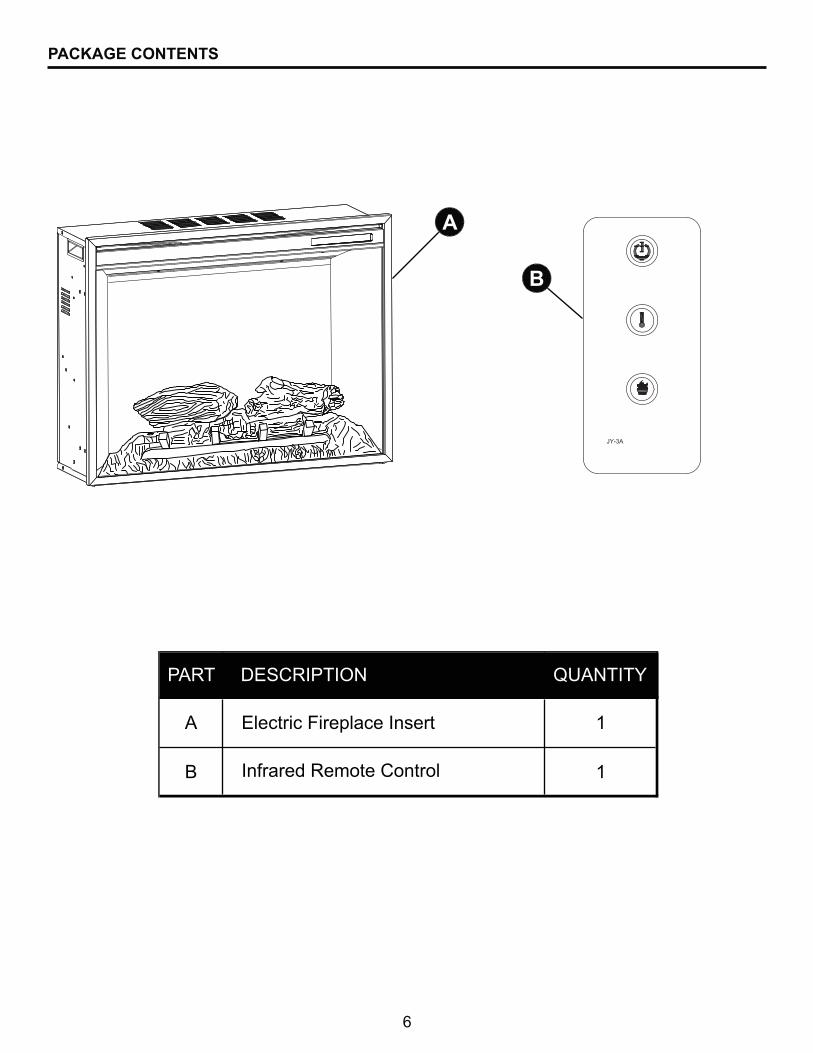
A 1
B 1
Electric Fireplace Insert
Infrared Remote Control
B
GHP
7
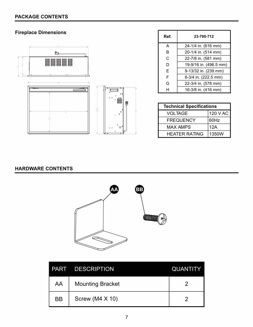
Fireplace Dimensions
PACKAGE CONTENTS
AA BB
Ref.
A 24-1/4 in. (616 mm)
B 20-1/4 in. (514 mm)
C 22-7/8 in. (581 mm)
D 19-9/16 in. (496.5 mm)
E 9-13/32 in. (239 mm)
F 8-3/4 in. (222.5 mm)
G 22-3/4 in. (578 mm)
H 16-3/8 in. (416 mm)
23-700-712
Y|LT�[< $X]�Y�AC
FREQUENCY �]^_
MAX AMPS 12A
^<�TER RAT=}[ 1350W
Technical Specifications
PART DESCRIPTION QUANTITY
AA 2
BB 2 Screw (M4 X 10)
Mounting Bracket
HARDWARE CONTENTS
8
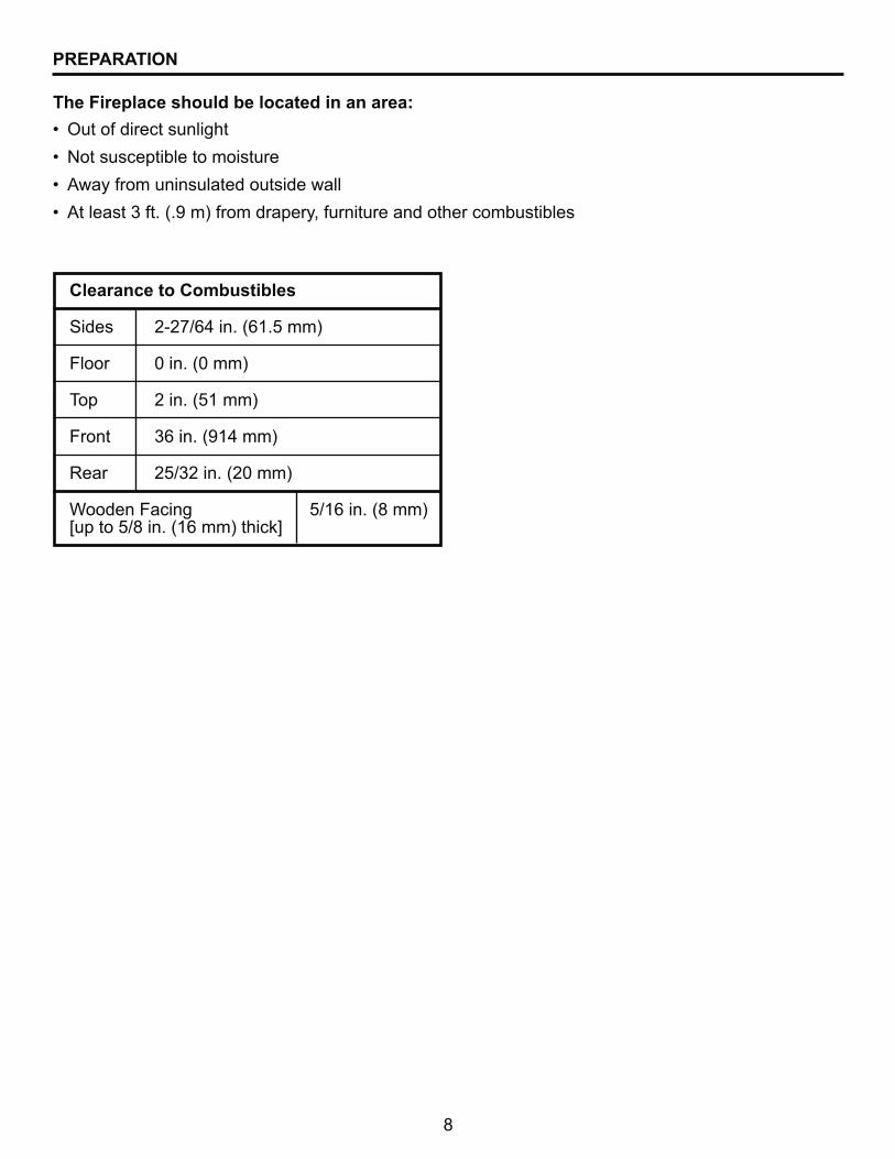
Clearance to Combustibles
Sides 2-27/64 in. (61.5 mm)
Floor 0 in. (0 mm)
Top 2 in. (51 mm)
Front 36 in. (914 mm)
Rear 25/32 in. (20 mm)
Wooden Facing 5/16 in. (8 mm) [up to 5/8 in. (16 mm) thick]
`� |������������ �������
`� }��� � ������������ ���
`� �������������� ��������� �������
`� ����� ��������H����V�����������"������������������������ ����
The Fireplace should be located in an area:
PREPARATION
9
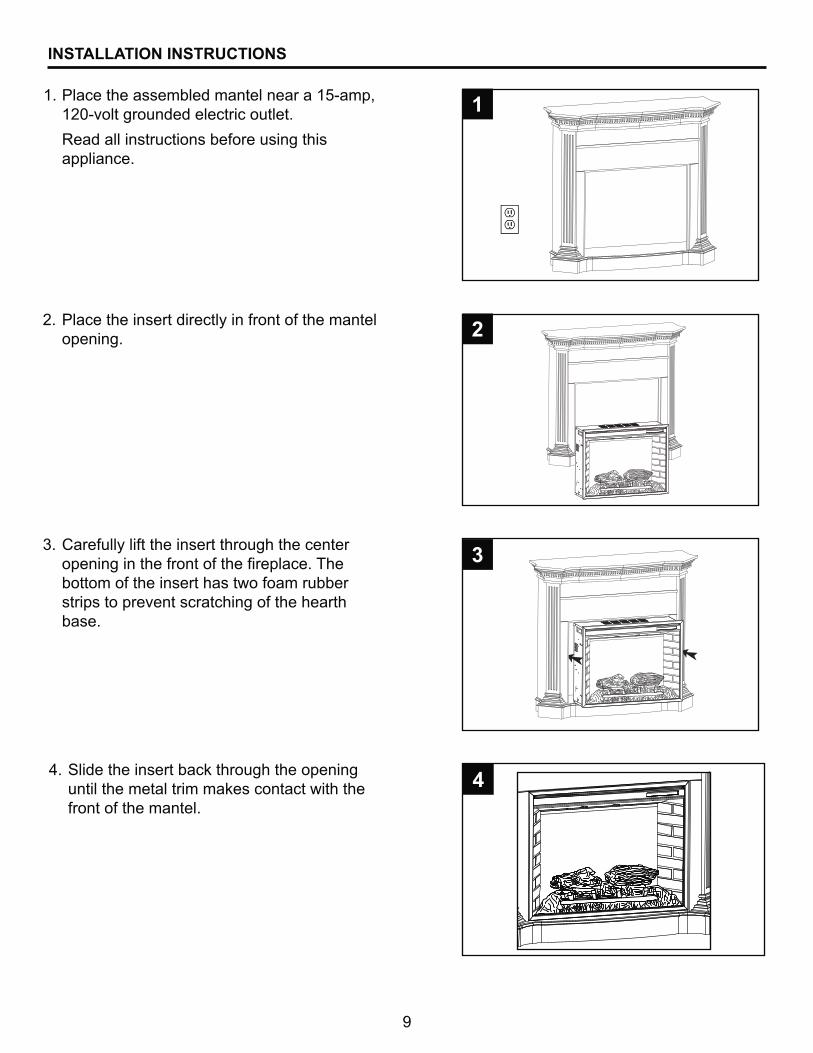
INSTALLATION INSTRUCTIONS
Place the assembled mantel near a 15-amp, 120-volt grounded electric outlet.
Read all instructions before using this appliance.
Place the insert directly in front of the mantel opening.
Carefully lift the insert through the center �������������������������������&���bottom of the insert has two foam rubber strips to prevent scratching of the hearth base.
1.
2.
3.
1
#
3
Slide the insert back through the opening until the metal trim makes contact with the front of the mantel.
4.4
10
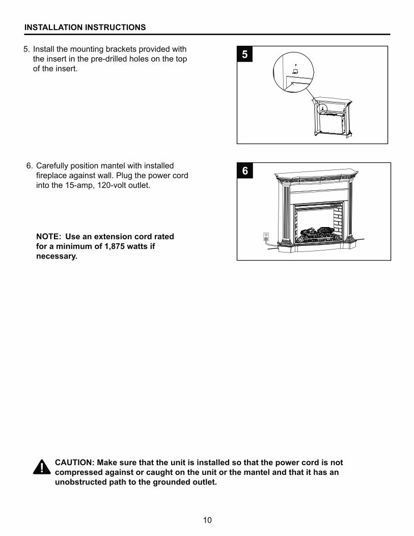
INSTALLATION INSTRUCTIONS
Install the mounting brackets provided with the insert in the pre-drilled holes on the top of the insert.
5.%
Carefully position mantel with installed ����������� �������������������������into the 15-amp, 120-volt outlet.
6.6
CAUTION: Make sure that the unit is installed so that the power cord is not compressed against or caught on the unit or the mantel and that it has an unobstructed path to the grounded outlet.
NOTE: Use an extension cord rated (�����������(��)*%������(necessary.
11
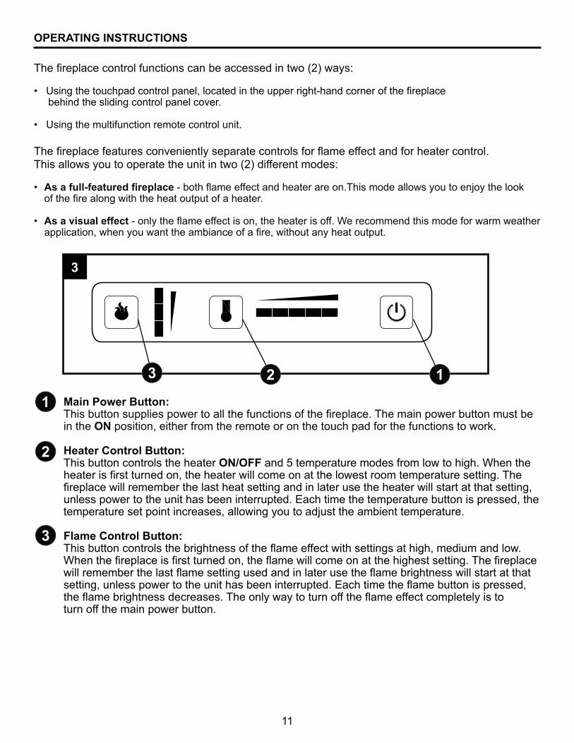
OPERATING INSTRUCTIONS
&������������� ������������ ������������ �����+�����������������������������This allows you to operate the unit in two (2) different modes:
`� +��(���/(���������������\������+�����������������������&�� ���������� ���������;���������!� � �������������������������������������������
`� As a visual effect�\���������+��������� ���"���������� ������Q������������ �������������������� � ���������"��������������������������������"�����������������������
&������������������������ ���������� ���������HXV���� ~
`� � ��������������������������"����������������������\���������������������� behind the sliding control panel cover.
`� � ���������������������������������������
1
#
3
Main Power Button:&�� �������� ��� ����������������������� ��������������&�������������������� �������in the ON position, either from the remote or on the touch pad for the functions to work.
Heater Control Button:This button controls the heater ON/OFF and 5 temperature modes from low to high. When the ������ ��� ����������"������������������������������ ��������������� �������&������������������������ ������ ������������������� �������������� ������������� �����"�unless power to the unit has been interrupted. Each time the temperature button is pressed, the temperature set point increases, allowing you to adjust the ambient temperature.
Flame Control Button:&�� ��������������� ����������� �������+������������� ����� ��������"����������������Q������������� ��� ����������"����+������������������������� �� �������&������������������������ ��+��� ������� ��������������� ����+���������� ������ ������������� �����"���� ������������������ ��������������<�����������+����������� �� �"������+���������� ����� ��&��������������������������+����������������� �������������turn off the main power button.
# 13
3

12
#
3
1
&�������������������������� ������������� ����������� ����������������+��? ����������������������!��&���������������������� ����������� ����������������|}?|���������������������������������=�������������� ��������������������������������������� ��"open the control panel sliding cover to access the touchpad buttons. The layout of the buttons ���������� ����������������������������� ��������� �������%"�� �������
$�������������������������$%\��"�$X]\����������������
2. Turn the power on. Flame will show on the back screen ������������
3. Remove plastic tab from inside battery compartment to activate remote control.
Z�������������������������������������������� +��? ��������� ���������� ������������ ������
Main Power Button: This button supplies power to all the functions of the �������&�������������������� ����������ON position, either from the remote or on the touch pad for the functions to work.
Heater Control Button: This button controls the heater ON/OFF and 5 temperature modes from low to high. When ��������� ��� ����������"������������������������������ ��������������� �������&�������������remember the last heat setting and in later use the heater will start at that setting, unless power to the unit has been interrupted. Each time the temperature button is pressed, the temperature set point increases, allowing you to adjust the ambient temperature.
Flame Control button: &�� ��������������� ����������� �������+������������� ����� ��������"����������������Q������������� ��� ����������"����+������������������������� �� �������&������������������������ ��+��� ������� ��������������� ����+���������� ������ ������������� �����"���� ������������������ ��������������<�����������+����������� �� �"����+���������� ����� ��&��������������������������+����������������� ����������������main Power button.
The plastic tab inside the batterycompartment MUST be removed before remote control will operate.
OPERATING INSTRUCTIONS
1
#
3
(Pull tab)
4
%

13
CARE AND MAINTENANCE
[�� �=����������~
Maintenance of Motors:
Cleaning:
Before attempting ANY maintenance:
1. Turn off power to the unit.
2. Unplug the power cord from outlet.
��� >��������������������� ������������
1. Under no circumstances should this product be operated with broken glass.
2. Do not strike or slam the glass.
3. Do not use abrasive cleaners to clean the glass.
4. This product uses tempered glass. Replacement of the glass supplied by the manufacturer � ������������������������� ������ ���
Always disconnect the appliance from the main power supply and allow it to cool before any servicing operation.
&������� �� ���������������������+�������������\��������������'�������������������������������������������������^����"���������������?�������������������������������������intake and exhaust, as well as the fan heater is recommended. For heavy or continuous use, periodic cleaning must be done more frequently. If the heater blows alternating cold and warm air, check the ������������������������������ �� �������������+����=����������� �������������"����������� ��be turned off and the fan replaced immediately in order to prevent further damage to the unit.
@������������������������"����������������������\�������������������������������sliding control panel cover, is to be done only using a soft cloth, slightly dampened in water (if needed, a small amount of dish soap can be added to the water) and dried using a clean, dry soft cloth. Cleaning of the screen diffuser is to be done using only water and a lint free cloth. DO NOT use any abrasive household cleaners as these products will damage the touch-padcontrols and the diffusing screen.

14
Disconnect power before servicing.
��������������\������������� ���������� ��������������������������������This wiring must be done in accordance with local codes and/or in Canada with the current CSA C22.1 Canadian Electrical Code, and for US installations, the National Electrical Code ANSI/NFPA NO 70.
If repairing or replacing any electrical component or wiring, the original wire routing, color coding and securing locations must be followed.
DANGER
Any electrical repairs or rewiring of this unit should be carried out by a licensed electrician in accordance with national and local codes.
@=z@�=&�*=�[z��
ELECTRIC WIRING DIAGRAM
CIRCUIT BOARD
Heating Indicator L HFlame IndicatorH/M/L
FUSE
1 Bl
ack
2 Black
4 Black
9 Black
15 White 6 White
7 White16 White
Temperaturesensor
Ember bed LED
Flame LED
10 White
Ther
mal
fuse
Ther
mal
cuto
ff
17 B
lack
11 W
hite
12 B
lue
3 Red
14 W
hite
Hea
ter e
lem
ent
Fan
heat
er
5 Bl
ack
Flam
e eff
ect m
otor
Pow
er I/
O
Hea
ter I
/O
Flam
e I/
O
L
N
AC120V / 60Hz
15
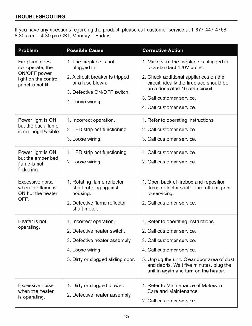
TROUBLESHOOTING
If you have any questions regarding the product, please call customer service at 1-877-447-4768, 8:30 a.m. – 4:30 pm CST, Monday – Friday.
Problem Possible Cause Corrective Action
Fireplace does not operate; the ON/OFF power light on the control panel is not lit.
Power light is ON ����������!�+��� is not bright/visible.
Power light is ON but the ember bed +���� ����� +��!�����
Excessive noise �������+���� �ON but the heater OFF.
Excessive noise when the heater is operating.
^����� ����� operating.
$��&��������� ����� plugged in.
2. A circuit breaker is tripped or a fuse blown.
3. Defective ON/OFF switch.
4. Loose wiring.
1. Incorrect operation.
2. LED strip not functioning.
3. Loose wiring.
1. LED strip not functioning.
2. Loose wiring.
$��z��������+����+����� shaft rubbing against housing.
X��*������+����+����� shaft motor.
1. Dirty or clogged blower.
2. Defective heater assembly.
1. Incorrect operation.
2. Defective heater switch.
3. Defective heater assembly.
4. Loose wiring.
5. Dirty or clogged sliding door.
$����!� ������������� ���������� ����� ��������$X]Y�������
2. Check additional appliances on the ������������������������� �������� on a dedicated 15-amp circuit.
3. Call customer service.
4. Call customer service.
1. Refer to operating instructions.
2. Call customer service.
3. Call customer service.
1. Call customer service.
2. Call customer service.
$��|�����!��������'������� ������+����+����� ������&������������������ to servicing.
2. Call customer service.
1. Refer to Maintenance of Motors in Care and Maintenance.
2. Call customer service.
1. Refer to operating instructions.
2. Call customer service.
3. Call customer service.
4. Call customer service.
5. Unplug the unit. Clear door area of dust �������� ��Q������������ "��������unit in again and turn on the heater.
16
&��������������������� ���������������������������� ���������������������������������material defects for a period of one year from date of purchase, subject to the following conditions and limitations.
1. &�� ���������������� ������ �������������������������� ����������������������instructions furnished with the product. Any alteration, willful abuse, accident, or misuse of the product shall nullify this warranty.
2. This warranty is non-transferrable, and is made to the original owner, provided that the purchase �� �����������������������_�� �����������������������
3. This warranty is limited to the repair or replacement of part(s) found to be defective in material or workmanship, provided that such part(s) have been subjected to normal conditions of use and ����"������ ���������� ��������������������������� ��� ������
4. The manufacturer may, at its discretion, fully discharge all obligations with respect to this warranty by refunding the wholesale price of the defective part(s).
5. Any installation, labor, construction, transportation, or other related costs/expenses arising from defective part(s), repair, replacement, or otherwise of same, will not be covered by this warranty, nor shall the manufacturer assume responsibility for same. Further, the manufacturer will not be responsible for any incidental, indirect, or consequential damages, except as provided by law.
6. All other warranties - expressed or implied - with respect to the product, its components and accessories, or any obligations/liabilities on the part of the manufacturer are hereby expressly excluded.
7. &��������������������� �� "������������_ �������������������� ��"������ ������"� any other liabilities with respect to the sale of this product.
8. The warranties as outlined within this document do not apply to non-manufacturer accessories used in conjunction with the installation of this product.
This warranty is void if:�V� &���������� ����������������� �� �����������������������"�+������������� damaging chemicals.�V��&��������� � ��;������������������� �������� ��������� ������c) Any alteration, willful abuse, accident, or misuse of the product.
IF WARRANTY SERVICE IS NEEDED . . .
1) Contact customer service at 1-877-447-4768, 8:30 a.m. – 4:30 pm CST, Monday – Friday. Make sure you have your warranty, your sales receipt, and the model/serial number of your product.XV��*|�}|&��&&<��&�&|�*|��}��G<zY=@<�Q|z���|�zG<>��
WARRANTY
GHP Group, Inc.8280 Austin Avenue�������[���"�=>�60053-3207
17
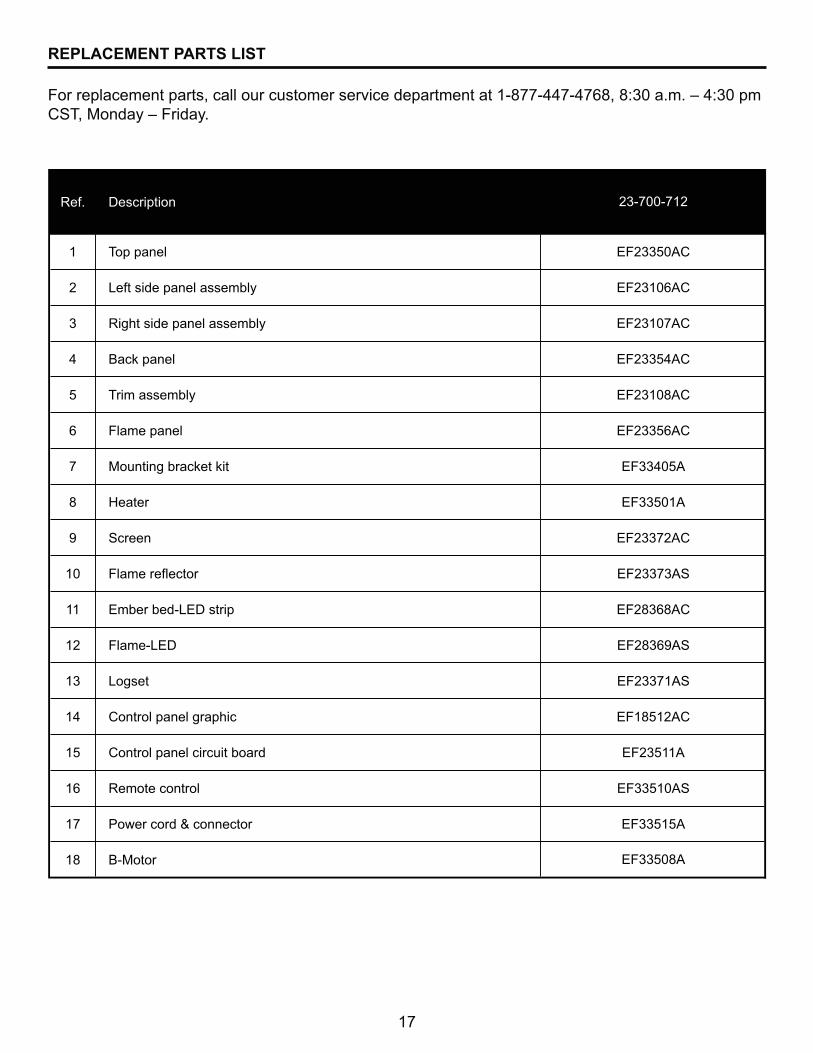
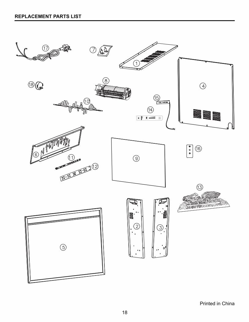
REPLACEMENT PARTS LIST
For replacement parts, call our customer service department at 1-877-447-4768, 8:30 a.m. – 4:30 pm CST, Monday – Friday.
Ref. Description
1 Top panel
2 Left side panel assembly
3 Right side panel assembly
4 Back panel
5 Trim assembly
6 Flame panel
7 Mounting bracket kit
8 Heater
9 Screen
10 Flame reflector
11 Ember bed-LED strip
12 Flame-LED
13 Logset
14 Control panel graphic
15 Control panel circuit board
16 Remote control
17 Power cord & connector
18 B-Motor
EF23108AC
EF23356AC
EF33508A
EF33405A
EF33501A
EF23372AC
EF23373AS
EF28368AC
EF28369AS
23-700-712
EF23371AS
EF18512AC
EF23511A
EF33510AS
EF33515A
EF23350AC
EF23106AC
EF23107AC
EF23354AC
18
Printed in China
REPLACEMENT PARTS LIST
19
FOYER ÉLECTRIQUEENCASTRABLE
MODÈLE #23-700-712
20-10-123
"89+";<8=�>@Z�8Z�@[Z\8�>@Z]�+��+�8<"^`������ �����������������������q������"89+";<8=�>@Z�8Z�@[Z\<��@8Z�^`������ �������������������������
��q(q������q�����������
AVERTISSEMENT!RESPECTEZ SCRUPULEUSEMENT LES DIRECTIVES DU PRÉSENT MANUEL
POUR PRÉVENIR LES CHOCS ÉLECTRIQUES, LES INCENDIES, LES DOMMAGES AINSI QUE LES BLESSURES GRAVES OU MORTELLES.
CONSIGNES IMPORTANTESVEUILLEZ LIRE CE MANUEL AVANT D’INSTALLER OU D’UTILISER LE FOYER.
Des questions, des problèmes, des pièces manquantes? ���������������������������������������"����������_���������� ���������������������1-877-447-4768,
����J����]���$�����]"�^}@" du lundi au vendredi.
��������������
JOIGNEZ VOTRE REÇU ICI
Z��q�����q���|||||||||||||||||||||||||||||||\����>�����||||||||||||||||||||||||||||||||
™
20
@9}["�+Z�^���� ��������������������������������������������������������������q���~�>������������������/�����������������������������������������q������������������������������������������������������
`������ ������������������>���������������>�����������������>����������(�����
TABLE DE MATIÉRES
Consignes de sécurité .................................................................................................................... 21
Contenu de l'emballage .................................................................................................................. 25
Préparation ..................................................................................................................................... 27
Directives d'Installation ................................................................................................................... 28
*������ �������� ����� ..................................................................................................................... 30
Entretien ......................................................................................................................................... 32
Schéma de câblage ........................................................................................................................ 33
Dépannage ..................................................................................................................................... 34
[������ .......................................................................................................................................... 36
>� ��� ���� ��������� ......................................................................................................... 37
21
Y����_���� �� ������������������������������������������������������� ����"�������� ��������� ����������������
$�� >� _����� �� �������� �������������� ���������
X�� @������ ����������� ������ ��������������������������� ������� "��������_�� ���'� ����� ������ ��G��������� �������������� "� ��_\��� �� ������ ������� ��������� ��_\��� ����� ������� ������ ���� "��� ����� ����� "�� ������� "� la literie, le papier, les vêtements et les rideaux, se trouvent au moins 914 mm (3 pi) ������������������
3. MISE EN GARDE : Faites preuve d’une extrême prudence lorsqu’un radiateur ���������q�����~��������q�����(��������������������������q���� ����������������� �������������(������������������������
Z��� *�� ����� ������� ���"���������_����;��� ����������� �������� ��� ������ ��
%��� }������ _�� ��������������������������������������������������"���������;�� �����������������"����� ����;������������������������������������������������� ����
��� @���_�����������������������������������������������
���� }������_�;���� ���������z���_�������� ���� ��������������������� ��������������������������� ������������������
J��� }������ _�� ������������'�������
���� >������������ ��� �������������������� ����� ���� ���������� "���� �������������������������������������� ��������}����_�;���� ������������������������������������������� ��������������������������������������������
$]�� ����_�������������������� �� ������� ��}������_�� ����������������������"������� ���� ��������������������� ������������_������������� �������������� ��������������������� ��������������
$$�� ���������������������"������_�� �������� ���� �������������"��� �����_�������� de la prise.
$X�� ������_�������������������������� ������������� ����������
$��� >�� ������� ���������"�����_��������������� ������ ������������������������'���� ������'"�������� ��������� �������@�������������������������"�@G��@XX�$���"���� ����� �� � �� ��������� ���'���\��"���'���� ������'���������������������������������"��}G=?}����}���]�
$Z�� }��� ��_�;���� ������;�"����������� ���"���� �� �������� ������������������� ����������� ���������������������� ������� ���� ������ ��� �� �����������������������������
$%�� �������������� ��� �� ���������"��������_�;���� �� ��� ������������� ������������������������������ �����}����_�� �������� ������ ����������"������������"�����les ouvertures pourraient se bloquer.
CONSIGNES DE SÉCURITÉ CONSERVEZ CES DIRECTIVES
22
$��� @������������� ���� ������ ������������ ���� ���� ��������� ����� �������� ��}������ _�� ������������������ ��"���������������� ������� ���+������ � ���� utilisés ou entreposés. Ce foyer et ses environs ne doivent pas servir de support de séchage ����� ������� ���������������� ��� ���}�������� ����������� �
$��� }������ _������������������ ����������� ����������&�������������� �������������������������� ��� �����������������������������������������"���������������������� �blessures.
$J�� ����_�������� ���������������������������� �������������� ����� ��� �� �����������> �������� ��� �������������� ������������G��������������������������� �"��������������� ��_\��� ������� ���������������������������>?@G����������� ��������������$%���H$�J�%����� V"�$X%�Y���'����"������������������������ ��� �����������$Z������������'���������� �������������������� �����������}�� ���� ����������� �������� ����������������� ���� ������������ ���"�������� �$%"X���H%]��V��}������_�� ��������������������������������_�� ��
CONSIGNES DE SÉCURITÉ

23
BROCHE DE MISE À LA
TERRE
COSSE DE MISE À LA
TERRE
VIS MÉTALLIQUE
BROCHE DE MISE À LA
TERRE
COUVERCLE DE LA BOÎTE DE SORTIE
MISE À LA TERRE
ADAPTATEUR
(A) (B)
(C)
(D)
Figure 1
CONSIGNES DE SÉCURITÉ
�����������q���������
\���������������~�������
�������������$%��"�$X]�Y"��]�^_������������� ���������� ����� �����=�� ���������������� ��������������������������������� ������ �������� ������même circuit pourraient causer le déclenchement du disjoncteur ou faire griller le �� ������� �������������� ��������������>������ ������������������������������$"J���H���V����� ������������������������������������_����� ��������������������������� ��������������> �������� ��� �������������� ������������G����� ���������������������� �"�� ��_\��� ������� ���������������������������>?@G����������� ��������������$%���H$�J�%����� V"�$X%�Y���'����"������������� ����������� ��� �����������$Z������������'���������� �������������������� �����������}�� ���� ����������� �������� ��������������� ������������ ���"�������� �$%"X���H%]��V��}������_�� ������������������������_�� �
Le câblage de la prise électrique doit être conforme aux codes du bâtiment �����'���������������������������������������� �����������"��������électrique ou de blessure.
}������ _�� �������� ����������������������������������_� �������������������������������������� ����������������������toute partie du circuit électrique qui a été immergée.
@���������� ����������������������������������$X]����� ��>�������� ������� ���������H���� ���������"������$V��������������H���� ��������@"������$V����� ����������� ���� ������� ������ ������� ������������'��� �����'���� ��>���� ����� ��������������������������������������������������� �������������������������������� ����������������� �����������}���� � ��_�� �������������� ������� ������� ���� ��� ���������� ���� �������
DANGER
Avertissement: Z>������� }+]�>�����������au Canada.
1
24
CONSIGNES DE SÉCURITÉ
�q�q��������
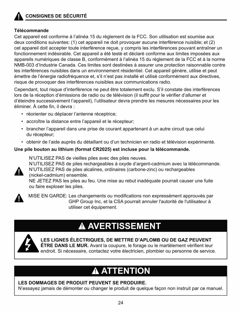
LES LIGNES ÉLECTRIQUES, DE METTRE D’APLOMB OU DE GAZ PEUVENT ÊTRE DANS LE MUR. ��������������"������������������������������������ ��������G����� ���"��������_���������������"������������ ������ �����
LES DOMMAGES DE PRODUIT PEUVENT SE PRODUIRE. }� ��_�;���� �������������������������������������������������� �����������������
@�������� ���������������������$%������������������@@��G�������� ������ �� ���� ���'�deux conditions suivantes: (1) cet appareil ne doit provoquer aucune interférence nuisible; et (2) cet appareil doit accepter toute interférence reçue, y compris les interférences pouvant entraîner un fonctionnement indésirable. Cet appareil a été testé et déclaré conforme aux limites imposées aux ����� ��������� ������ ��"������������������������$%������������������@@�������������}��\]]����=��� ����@�������@ ������ � ����� ���� ���� ������������������� �������������� ���������� ���� ��� ���� ����������������� ��������@�������������"������ ������������������������������������"� ������ ��� ��� ������������� ����������������'�������� "�risque de provoquer des interférences nuisibles aux communications radio.
@�����"�������� ���������������������������������'�����G������� ����� ���������� ���� ������������������� ��� �������������������� ����H��� �������������������������������������� ��� �������������V"�������� ���������������� �� �� ���� ��� ������ ������������������"���������~��
� `� �����������������������������������
� `� �������������� ����������������������������
� `� ������������������� ������ ���������������������������������������������� du récepteur;
� `� ������������������� ������������������������������������������������ ����'��������
<����������������������(������"#$#%'�����������������q�q���������
}��&=>=G< ���G�������� ��� ������ ��� ���� ��}��&=>=G< ���G����� ���������� ����'����������\����������������������������}��&=>=G< ���G����� �������� "��������� �H������\_���V������������� � (nickel-cadmium) ensemble. NE JETEZ PAS les piles au feu. Une mise au rebut inadéquate pourrait causer une fuite ou faire exploser les piles.
AVERTISSEMENT
ATTENTION
�=G<�<}�[�z*<~�> ��������� ��������������� �����'� ����������� ������� � ���������[^��[����=��"������@G������������������¢������������¢����� ��������� utiliser cet équipement.
25
CONTENU DE L'EMBALLAGE
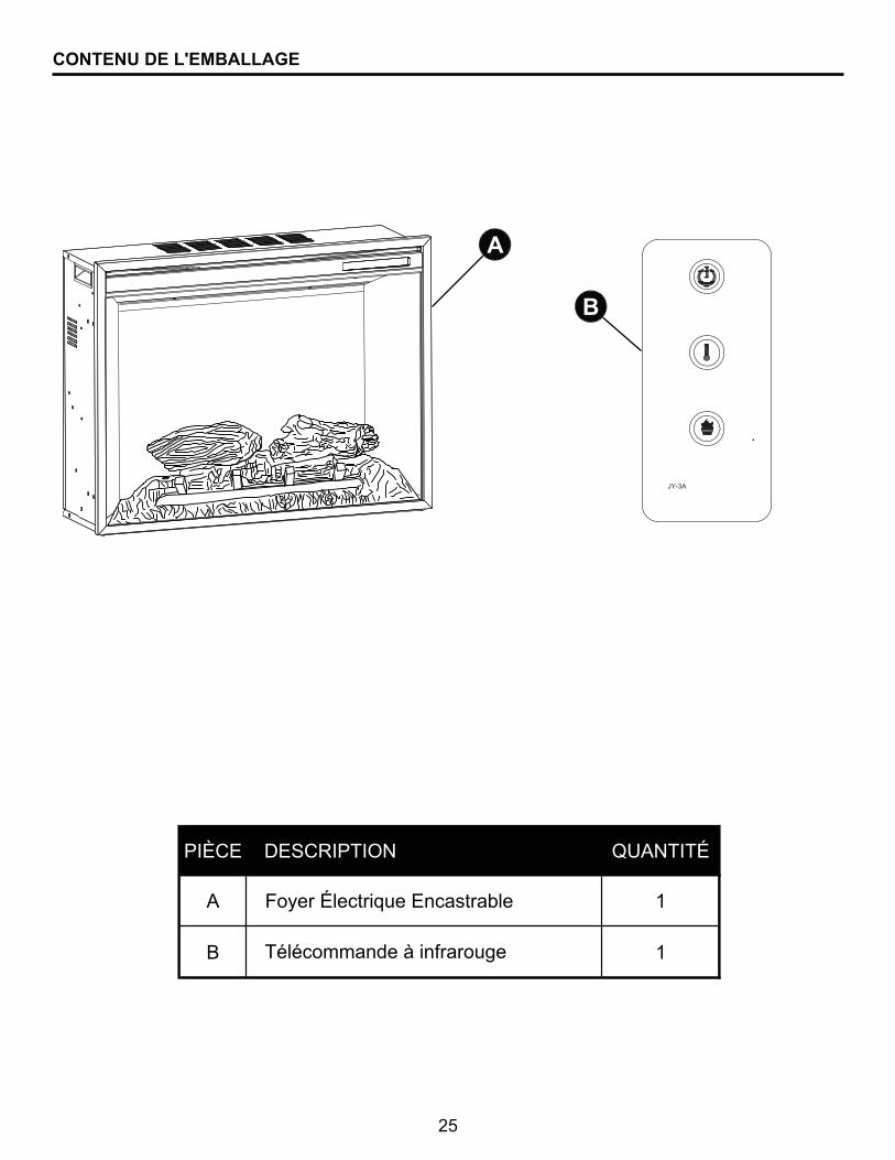
PIÈCE DESCRIPTION QUANTITÉ
A 1
B 1
Foyer Électrique Encastrable
Télécommande à infrarouge
A
B
GHP
26
CONTENU DE L'EMBALLAGE
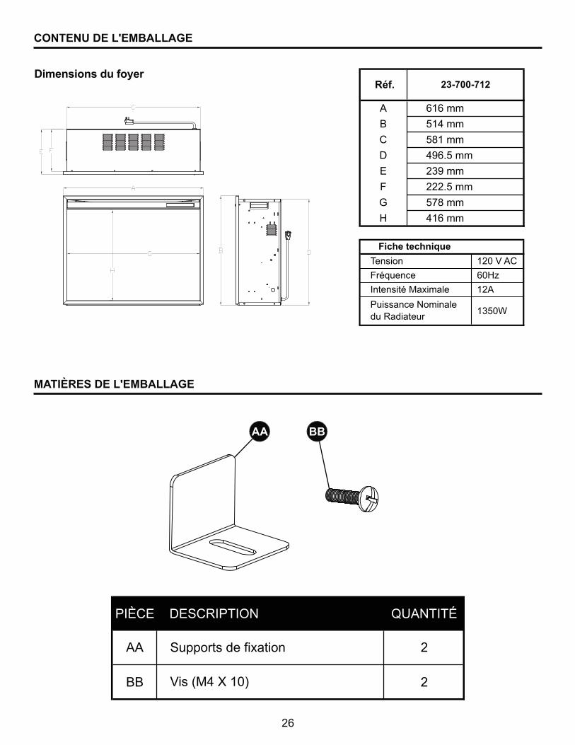
Dimensions du foyer
AA BB
PIÈCE DESCRIPTION QUANTITÉ
AA 2
BB 2
Supports de fixation
Vis (M4 X 10)
MATIÈRES DE L'EMBALLAGE
Réf.
A 616 mm
B 514 mm
C 581 mm
D 496.5 mm
E 239 mm
F 222.5 mm
G 578 mm
H 416 mm
23-700-712
$X]�Y�AC
�]^_
12A
1350W
Fiche technique
Tension
Fréquence
Intensité Maximale
Puissance Nominale du Radiateur
27
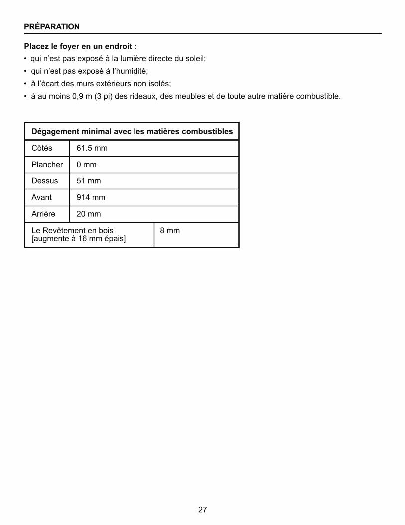
\q������������������������������������������
Côtés 61.5 mm
Plancher 0 mm
Dessus 51 mm
Avant 914 mm
������� X]���
Le Revêtement en bois 8 mm ¤���������$�������� ¥
`� ������ ��� �'� ����������������������� �����
`�������� ��� �'� ���������������
`������������� ���� �'������ ������ ��� �
`����������� �]"����H���V�� ������'"�� ����� ��������������������������� �����
}���� ��(���������������^
PRÉPARATION
28
DIRECTIVES D’INSTALLATION
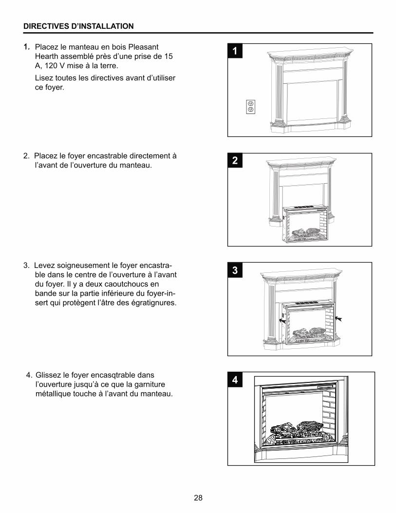
$�� ����_��������������� ���� ����^������ ������� �������� ���$%��"�$X]�Y��� �����������
� >� _����� �� �������� �������������� ��ce foyer.
����>�_� ����� �������������� ���-������ ������������������������������du foyer. Il y a deux caoutchoucs en bande sur la partie inférieure du foyer-in- �����������������¦���� ����������� �
X�������_����������� �����������������������������������������������
1. 1
#
3
[�� _����������� ���������� �����������;� ���������������������� ������������������������������������
4.4
29
+��8Z�@[Z^+����� /���������(��������������q�������������������>����������������������������q������q�����>����q����������������������������������������������~��������
DIRECTIVES D’INSTALLATION
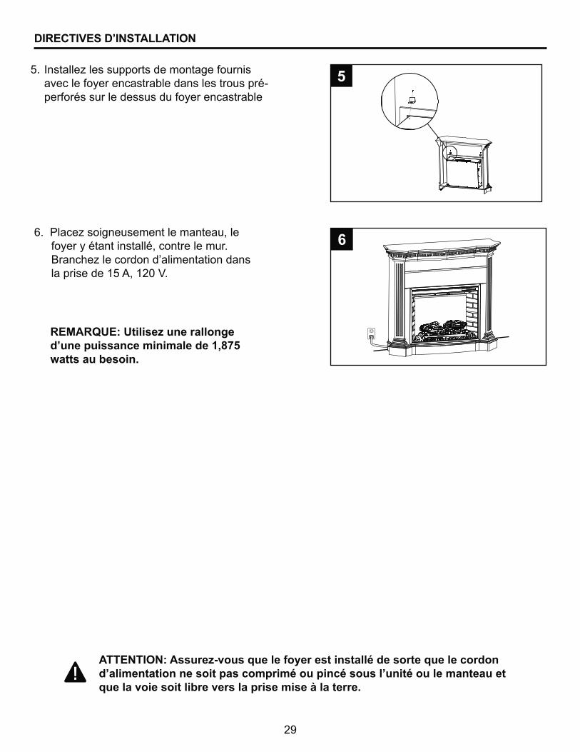
=� ����_�� � ���� ���������������� �avec le foyer encastrable dans les trous pré-perforés sur le dessus du foyer encastrable
5. %
��������_� ����� ������������"���foyer y étant installé, contre le mur. ������_��������������������������� ������ ���$%��"�$X]�Y��
6
"89+";<8^<������ ������������>������������������������)*%watts au besoin.
30
DIRECTIVES D’UTILISATION
>��������������������� �������� ��� ����� �������������+������������������
@ �������� ��������������� �������������'�HXV��������� ���� �~
`� ��Comme foyer complet�§���������+����������������� ����������������@�������� � �����������������������������������������������������������������������������
`� ��Comme effet visuel seulement�§� �����������+���� ������������"������������ ����� � fonction. Nous recommandons ce mode lorsque la température est élevée, pour apprécier � �������������������� �� ���������������
*�'�HXV������� �������������������'�������ons de commande du foyer :
`� ������������������������������������"���� �������� �������������������������������������� ��� couvercle coulissant du panneau de commande.
`� �����������������������������������������
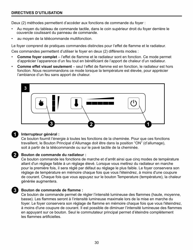
@������������q�q���^@������������������������������ �� ��������� ����������������������� ��������� �����������"����������������������������������������� ����� ������¨|}©�H���������V"� �������������������������������� �����������������������������
Bouton de commande du radiateur :@����������������� ��������� ���������������������� ������������� ��������������������¢����������������������������������>�� ������ �����_������������������������������������� "���� ��������������������������������� ��������>��������� ����� ��������������������������������������� ������� ��¢������_"������� ��¢��������������������@�������� ������� ����_� ������������&�������H��������V"�����������générée augmentera. �����������������������^@������������������������������������ ���������� �� �+��� �H����"������"��� V��> �+��� � ������������� ���������� ���'�������� �������� ������������������>��������� ����� ������������+���������������������� ������� ��¢������_"������� ��¢������������������� =�� ��� �������������������� ���������� �� �+��� ���������� �������������G������������������������������������������������ �+��� ���������� ���
1
#
3
# 13
3
31
>������������������������������� ������������ ���������������������+�������������������������������> �������� ���������������������������������������������������������������������������������������������� �����������G����� ������_������ �����������������������������"�����_���������������� ������������������������������������'������� �������������������@�� ���_�� ��������� ����� �����%������������������� � ������� ������� ����������tactile et de la télécommande.
$�� ������_�������������� ������ ���$%��"�$X]�Y���
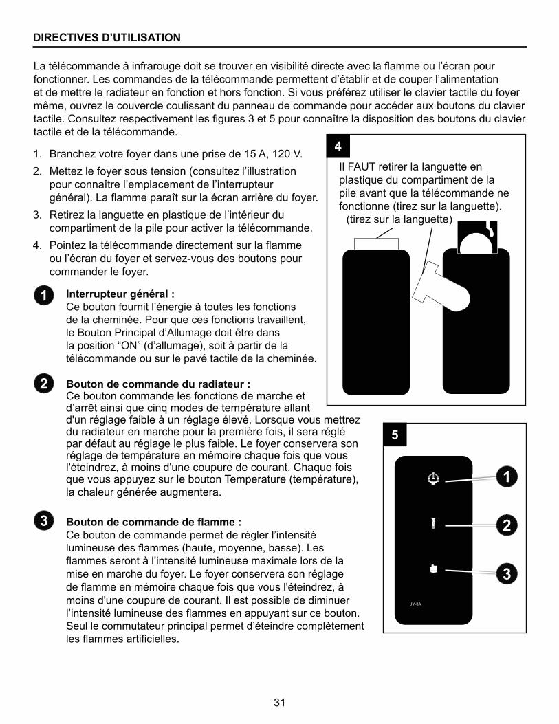
X�� ���_�������� �� ��� ����H��� ���_������� ��������������������������������������������� �������V��>��+���������� ���������������������������
��� z���_���������������� ��������������������� compartiment de la pile pour activer la télécommande.
Z�� �����_������������������������� ������+���� ��������������������� ��_\��� �� ������� �����commander le foyer.
@������������q�q���^@������������������������������ �� ��������� �����de la cheminée. Pour que ces fonctions travaillent,���������������������������������������� ����� ������¨|}©�H���������V"� �����������������télécommande ou sur le pavé tactile de la cheminée.
Bouton de commande du radiateur :Ce bouton commande les fonctions de marche et ����������� ������������� ��������������������¢����������������������������������>�� ������ �����_������������������������������������� "���� ���������par défaut au réglage le plus faible. Le foyer conservera son réglage de température en mémoire chaque fois que vous �¢������_"������� ��¢��������������������@�������� ������� ����_� ������������&�������H��������V"�la chaleur générée augmentera.
�����������������������^@������������������������������������ ���������� �� �+��� �H����"������"��� V��> �+��� � ������������� ���������� ���'�������� ������mise en marche du foyer. Le foyer conservera son réglage ��+���������������������� ������� ��¢������_"���moins d'une coupure de courant. Il est possible de diminuer ������ ���������� �� �+��� ���������� �������������G������������������������������������������������ �+��� ���������� ���
DIRECTIVES D’UTILISATION
1
#
3
Il FAUT retirer la languette en plastique du compartiment de la pile avant que la télécommande ne ����������H���_� �������������V�
#
3
1
(���_� �������������)
4
%
32
ENTRETIEN
Renseignements sur la vitre :
Entretien des moteurs :
Nettoyage :
$�� }������ _�;���� �������� ���������� ����� ��
X�� }����_�� ������������������_�� �
��� }������_�� ��������������������������� ���
Z�� @������ �����������������������@���_�������������������������������������������� � ����������������������
Avant TOUT entretien :
$�� @��_�����������������������
X�� *�������_������������������������������� �
��� >�� _����������������� ���������������������
\q������� ����������(�������>������������q��������������������������� ��(������(������avant tout entretien.
> ������ ������ � � �������������������������������� ���+������+������������������ � ���������������������� �������� �����'�������������������� ����=�� ��������� �������������������������������� ����� ��������������������������������� ������"������ ���������������������������������������}����_��� ���������������������� �������� ���������� ���������������G����������������� �����������������������������������������"������_� ������������������������������� ��� ������ ��� ����������������������������G����������������������� ��������"����_����������� ���������"��� ������_����������������������������������������������dommage au foyer.
}�������������������������"���� �������� �������������������������������������������������������������� ���"�'��� ������������������������'����������������������H���� ���"��;���_�������� ���������� ���������V"��� �� ���_\�������������������-�������'"������� ���}����_�������� ������������� ����������������������������������pelucheux. N’UTILISEZ PAS de produits de nettoyage domestiques car ces produits endommageront � �������� ����������������������������������� ����
33
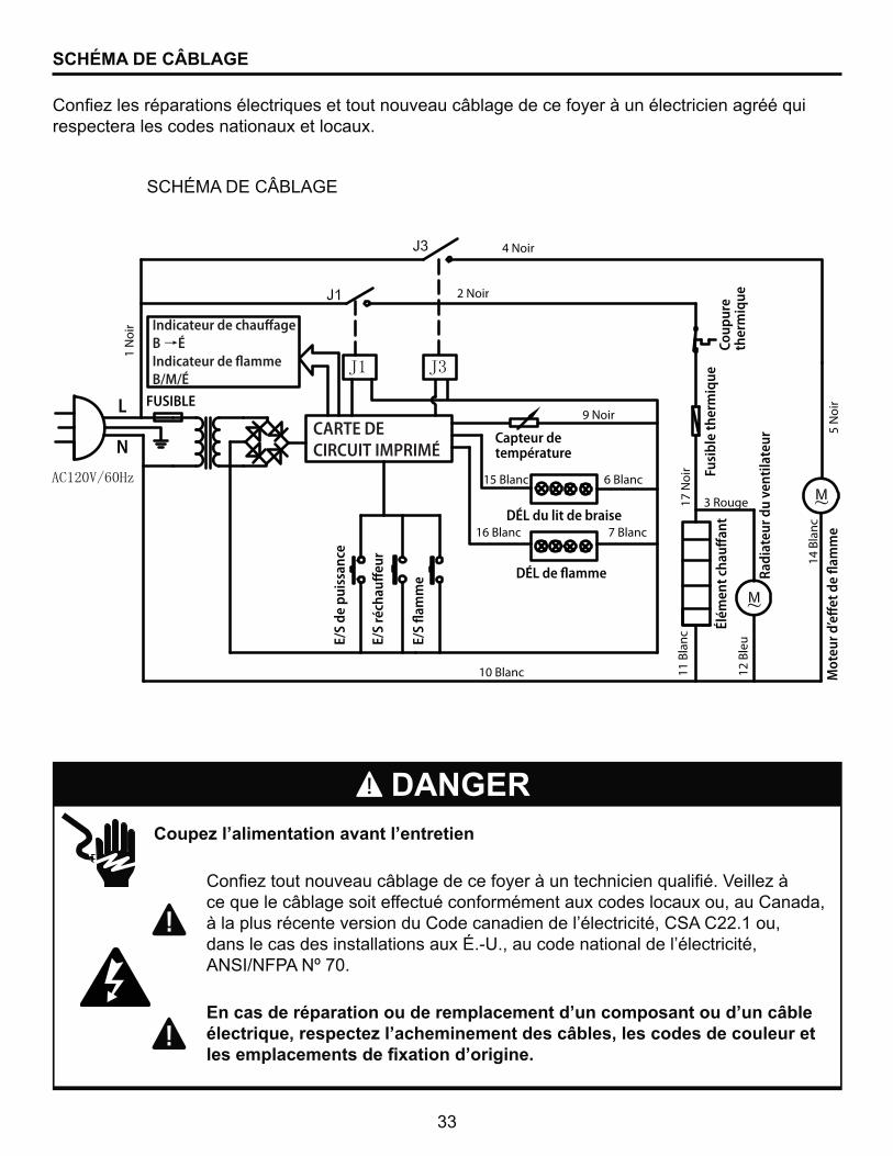
����� �>������������������>���������
� @���_��������������¦�������������������������������������Y���_��� ce que le câblage soit effectué conformément aux codes locaux ou, au Canada, � ������� ��������� �������@�������������������������"�@G��@XX�$���"����� ��� ����� �� ��� ��������� ���'���\��"�������������������������������"������������� �}G=?}����}���]�
8�������q�������������������������>��������������>������� q������������������ �>����������������������������������������� ������������������������>��������
DANGER
@���_�� ���������� ��������� ����������������¦���������������������������������������respectera les codes nationaux et locaux.
G@^����*<�@ª�>�[<
SCHÉMA DE CÂBLAGE
CARTE DECIRCUIT IMPRIMÉ
Indicateur de chauffage B ÉIndicateur de flammeB/M/É
FUSIBLE
1 N
oir
2 Noir
4 Noir
9 Noir
15 Blanc 6 Blanc
7 Blanc16 Blanc
Capteur de température
DÉL du lit de braise
DÉL de flamme
10 Blanc
Fusi
ble
ther
miq
ueCo
upur
eth
erm
ique
17 N
oir
11 B
lanc
12 B
leu
3 Rouge
14 B
lanc
Élém
ent c
hauff
ant
Radi
ateu
r du
vent
ilate
ur
5 N
oir
Mot
eur d
’eff
et d
e fla
mm
e
E/S
de p
uiss
ance
E/S
réch
auff
eur
E/S
flam
me
L
N
34
DÉPANNAGE
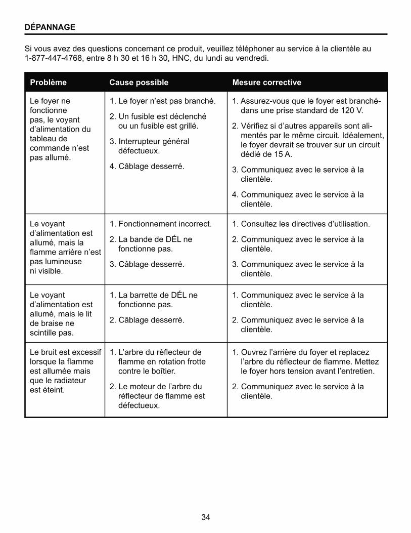
G����� ���_�� ��� ���� �������������������"������_������������� �������������������� $\J��\ZZ�\Z��J"�����J����]���$�����]"�^}@"��������������������
Problème Cause possible Mesure corrective
Le foyer ne fonctionne pas, le voyant �����������������tableau de ���������� ��pas allumé.
Le voyant �������������� ��allumé, mais la +������������� ��pas lumineuse ni visible.
Le voyant �������������� �� allumé, mais le lit de braise ne scintille pas.
Le bruit est excessif ��� ������+����est allumée mais que le radiateur est éteint.
$��>�������� ��� ���������
2. Un fusible est déclenché ou un fusible est grillé.
3. Interrupteur général défectueux.
4. Câblage desserré.
1. Fonctionnement incorrect.
2. La bande de DÉL ne fonctionne pas.
3. Câblage desserré.
1. La barrette de DÉL ne fonctionne pas.
2. Câblage desserré.
$��>�����������+�������+���������������������contre le boîtier.
X��>���������������������+�������+���� ��défectueux.
$��� ��_\��� ����������� ���������-��� ������ � ����������$X]�Y�
X��Y����_� �������� ������ � �������-mentés par le même circuit. Idéalement, le foyer devrait se trouver sur un circuit dédié de 15 A.
���@��������_������� ���������� ��������
Z��@��������_������� ���������� ��������
$��@�� ���_�� �������� �������� ������
X��@��������_������� ��������� ��������
���@��������_������� ���������� ��������
$��@��������_������� ���������� ��������
X��@��������_������� ��������� ��������
$��|���_������������������������_�������������+�������+��������_����������� ��� �������������������
X��@��������_������� ���������� ��������
35
DÉPANNAGE
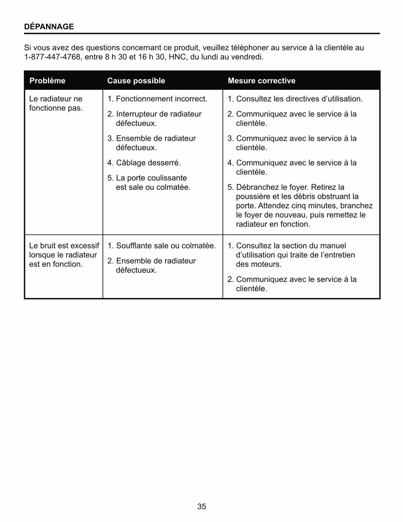
G����� ���_�� ��� ���� �������������������"������_������������� �������������������� $\J��\ZZ�\Z��J"�����J����]���$�����]"�^}@"��������������������
Problème Cause possible Mesure corrective
Le bruit est excessif lorsque le radiateur est en fonction.
Le radiateur ne fonctionne pas.
$��G���+���� ��������������
2. Ensemble de radiateur défectueux.
1. Fonctionnement incorrect.
2. Interrupteur de radiateur défectueux.
3. Ensemble de radiateur défectueux.
4. Câblage desserré.
5. La porte coulissante est sale ou colmatée.
$��@�� ���_���� ���������������������� ��������������������������� des moteurs.
X��@��������_������� ��������� ��������
$��@�� ���_�� �������� �������� ������
X��@��������_������� ��������� ��������
���@��������_������� ��������� ��������
Z��@��������_������� ��������� ��������
%��*�������_���������z���_������ ������� ������ ��� ����������porte. �����_����������� "�������_����������������"��� �����_��� radiateur en fonction.
36
Le fabricant garantit que votre nouveau foyer électrique est exempt de défaut de fabrication ou de ��������'����������������������������������������"��������������� ���������� ���� �restrictions suivantes.
1. Ce foyer électrique doit être installé et utilisé en tout temps conformément aux directives ���� ������������������� ��������� �����������������������������"������� ����������"� un accident ou une mauvaise utilisation du produit invalide la présente garantie.
2. @������������� ��� ����� ����������� ������������������������������"��������������������������������_���������� ��������� ����������� �
3. @����������� �������������������������������������� ���� ������� ������ ������� �����������'�����������������"���������� ���� ��������������;������������ ��������������������������'"������� ����������������������������� ����������������������� �
4. >������ ���"��� ���� �������"� ������������������������������������������ ������������������� ��������'������ �� ���� �������� �
5. &�������� ����� ���������"�������\��«���"��������������"������� ���"���������� ����� �����' ������������ ���� �������� "���������������"�����������������������������������������"��� ����� ������� �� ������ �������������������� ���� ���������� �� ��������������������*��� "�������� ��� ��� �� �� ����� ������� ���� ��� �ou consécutifs, sauf conformément aux dispositions de la loi.
6. Toutes les autres garanties, explicites ou implicites, sur le produit, ses composants et ses ��� ��� ���� ������������������������������ �� ����������������� � ����'� �����exclues par les présentes.
7. >������ ���� �������������� ������� ���� ���"��� ������"������������ �� ����������������������������������
8. Les garanties énoncées dans le présent document ne couvrent pas les accessoires qui ne ���������� �������������������� � ������������������ ���������������������
����������������������q���^
�V� >����������������� ����� �������� �������������������������"����+������������� � produits chimiques nocifs.
�V� >������ ��'� ���������������������������� ������������� ������ �������� �
�V� >�������������������;������������������"��������� ������������������������� ������ �����"� ou a subi un accident.
SERVICE AU TITRE DE LA GARANTIE . . .
$V� @��������_������� �����������������������������������$\J��\ZZ�\Z��J"�����J����]������ $�����]"�^}@"���������������������� ��_\��� ��������������� �������������"����������� �� ��������� ������ ������� ������������� �������������������������������
XV� }<�&<}&< ���G�*<�z���z<z�><��z|*�=&�Y|�G\�¬�<�
GARANTIE
GHP Group, Inc.8280 Austin Avenue�������[���"�=>�60053-3207
37
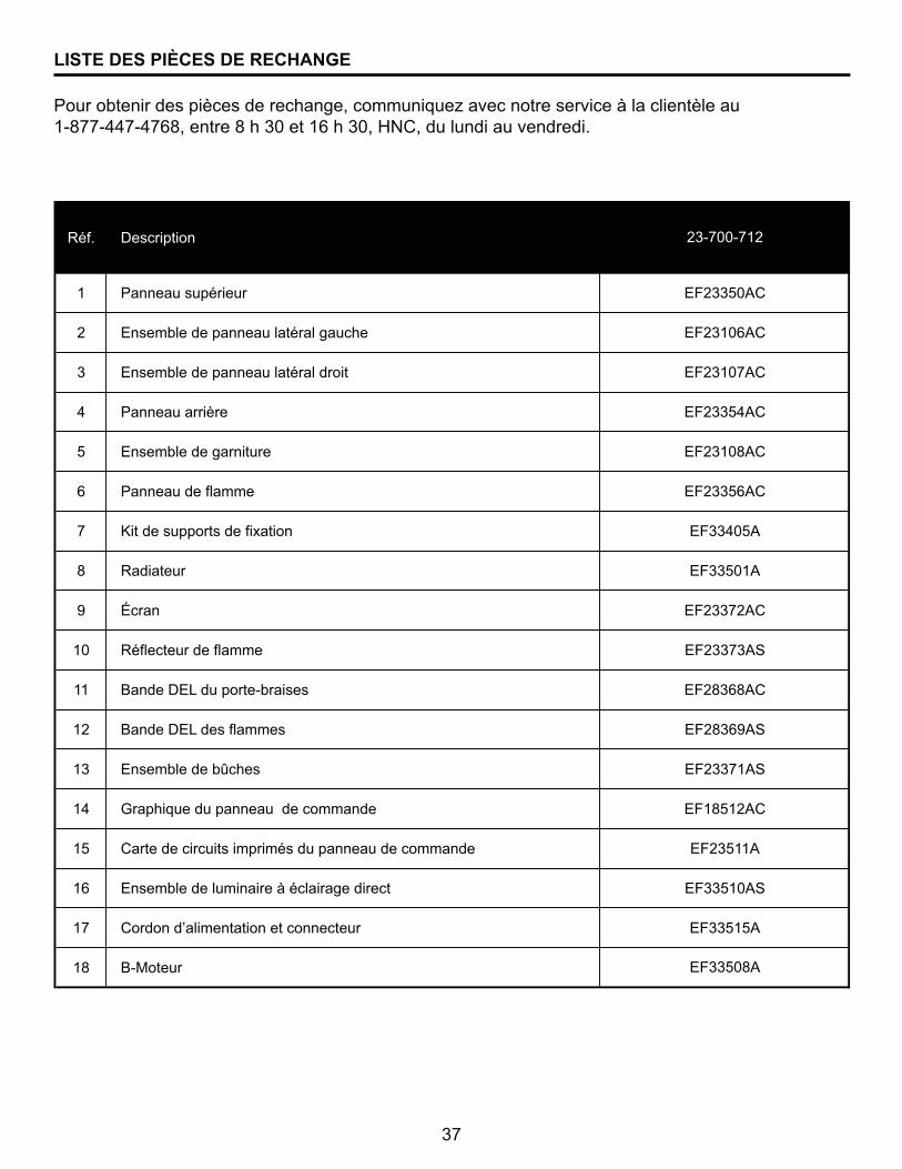
LISTE DES PIÈCES DE RECHANGE
������������� ���� ���������"����������_���������� ��������������������� $\J��\ZZ�\Z��J"�����J����]���$�����]"�^}@"��������������������
Réf. Description
1 Panneau supérieur
2 Ensemble de panneau latéral gauche
3 Ensemble de panneau latéral droit
4 Panneau arrière
5 Ensemble de garniture
6 Panneau de flamme
7 Kit de supports de fixation
8 Radiateur
9 Écran
10 Réflecteur de flamme
11 Bande DEL du porte-braises
12 Bande DEL des flammes
13 Ensemble de bûches
14 Graphique du panneau de commande
15 Carte de circuits imprimés du panneau de commande
16 Ensemble de luminaire à éclairage direct
17 Cordon d’alimentation et connecteur
18 B-Moteur
EF23108AC
EF23356AC
EF33508A
EF33405A
EF33501A
EF23372AC
EF23373AS
EF28368AC
EF28369AS
23-700-712
EF23371AS
EF18512AC
EF23511A
EF33510AS
EF33515A
EF23350AC
EF23106AC
EF23107AC
EF23354AC

38
Imprimé en Chine

39
ACCESORIO PARACHIMENEA ELÉCTRICA
MODELO #23-700-712
20-10-123
¡ADVERTENCIA!SI NO SE SIGUE CON PRECISIÓN LA INFORMACIÓN DE ESTE MANUAL, SE
PUEDE PRODUCIR UNA DESCARGA ELÉCTRICA O UN INCENDIO QUE PRODUZCA DAÑOS A LA PROPIEDAD, LESIONES PERSONALES O MUERTE.
INSTRUCCIONES IMPORTANTESLEA ESTE MANUAL ANTES DE INSTALAR Y USAR EL ELECTRODOMÉSTICO
�}���������������������� ��(���������Antes de volver a la tienda, comuníquese con nuestro departamento de Servicio al Cliente llamando al 877-447-4768,
de 8:30 a.m. a 4:30 p.m. hora central estándar, de lunes a viernes.
��������������
ADJUNTE SU RECIBO AQUÍ
Número de serie _____________________________ Fecha de compra _____________________________
@Z]�+�+\["^\����������������������������q������CONSUMIDOR: Conserve este manual para referencia futura.
™
40
IMPORTANTE: lea con atención todas las instrucciones y advertencias antes de ����� ����������������]���������������������������������������������� ����������q�����������������������������������������������������������������
ÍNDICE
Información de seguridad ............................................................................................................... 41
Contenido del paquete ..................................................................................................................... 45
Preparación ..................................................................................................................................... 47
Instrucciones de instalación ........................................................................................................... 48
Instrucciones de operación............................................................................................................. 50
Cuidado y mantenimiento ............................................................................................................... 52
Diagrama del cableado eléctrico .................................................................................................... 53
Solución de problemas ................................................................................................................... 54
[�����®�.......................................................................................................................................... 56
>� ������_� ����� ��............................................................................................................ 57
Lea estas instrucciones de instalación y funcionamiento ������������ ��������������q������

41
Lea y comprenda completamente este manual antes de intentar ensamblar, usar o instalar el producto.
1. Lea todas las instrucciones antes de usar este electrodoméstico.
2. Este electrodoméstico se calienta cuando está en funcionamiento. Para evitar quemaduras, �������� ����� ������� ������������ ������G�� ��������"���������� �����;� ����� ��� ����������������� ��������������������� ���+����� "���������� "��������� "� ropa de cama, papeles, ropa y cortinas al menos a 914,4 mm (3 pies) de la parte delantera de este electrodoméstico.
3. PRECAUCIÓN: Se debe tener extrema precaución cuando niños o personas discapacitadas usen un calentador o cuando se use cerca de ellos, y siempre que el calentador se deje funcionando sin vigilancia.
4. Si es posible, siempre desenchufe este electrodoméstico cuando no lo use.
5. No opere ningún calentador con un cable o enchufe dañados, o después de fallas del mismo, de que se haya dejado caer o dañado de cualquier forma.
��� &����������¯���� ����������� ������������_��������������������������
���� ��;���������������� ������� ������������� ����������� ������>� ��_� ���� � ���������������������¯�� ���������_������ �������������������������� �� electrodoméstico.
8. No lo use en exteriores.
9. Este calentador no se debe usar en el baño, lavadero y en espacios húmedos similares interiores. Nunca coloque este calentador donde se pueda caer dentro de una bañera u otro contenedor de agua.
10. No coloque el cable debajo de una alfombra. No cubra el cable con alfombras, tapetes o ������ ��@��������������;� ���_��� �����°� ���������������� ��������_���������
11. Para desconectar este electrodoméstico, gire los controles a la posición de apagado y luego retire el enchufe del tomacorriente.
12. Conecte únicamente a un tomacorriente con la debida puesta a tierra.
13. Cuando está instalado, este electrodoméstico se debe poner a tierra según los códigos locales, según los Códigos de Electricidad de Canadá CSA C22.1 o, para instalaciones en EE.UU., siga los códigos locales y el código nacional de electricidad, ANSI/NFPA No. 70.
$Z�� }���������_�����;�� �'���±� ���������������������� �������� ��� �������������¯�"�ya que pueden provocar descargas eléctricas, incendios o daños en el electrodoméstico.
15. Para evitar incendios, no bloquee las entradas ni salidas de aire de ninguna manera. No use ���� ����� ������� "��������������"�������� �������� � ��������������
$��� < ����������� ����������� �����������_� ������� ����_� ��������������� ��������� �o que echan chispas. No lo use en áreas donde se use o almacene gasolina, pintura o líquidos ��+����� ��< ����������� �������� ����� �������������;��������� �������"���� tampoco se deben colgar calcetas navideñas o decoraciones en el electrodoméstico o cerca de éste.
INFORMACIÓN DE SEGURIDAD GUARDE ESTAS INSTRUCCIONES
42
17. Utilice este electrodoméstico sólo como se describe en este manual. Cualquier otro uso no recomendado por el fabricante puede causar incendios, descargas eléctricas o lesiones personales.
$J�� <���������_���'�� ��� ��������� "������������ ����� ������������ �������������� incendio. Las extensiones eléctricas son sólo para uso temporal. De ser necesaria una '�� �¯����������"�� ������ ���������������>?@G�"���� ������������$%���H$J�%�QV"� $X%�Y�������°'��������$Z��Q[�������®����������������������� ���������� �����������con puesta a tierra. Se recomienda una extensión eléctrica para trabajo pesado de la menor longitud posible para la conexión, que no sobrepase los 15,24 m (50 pies). No enrolle ni cubra la extensión eléctrica.
INFORMACIÓN DE SEGURIDAD
43
CLAVIJA CON PUESTA A TIERRA
PUESTA A TIERRA
TORNILLO DE METAL
CLAVIJA CON PUESTA A TIERRA
ADAPTADOR
(A)
(C)
(D)
TAPA DE LA CAJA DEL TOMACORRIENTE
PUESTO A TIERRA
Figura 1
INFORMACIÓN DE SEGURIDAD
����������q������
Instrucciones de puesta a tierra
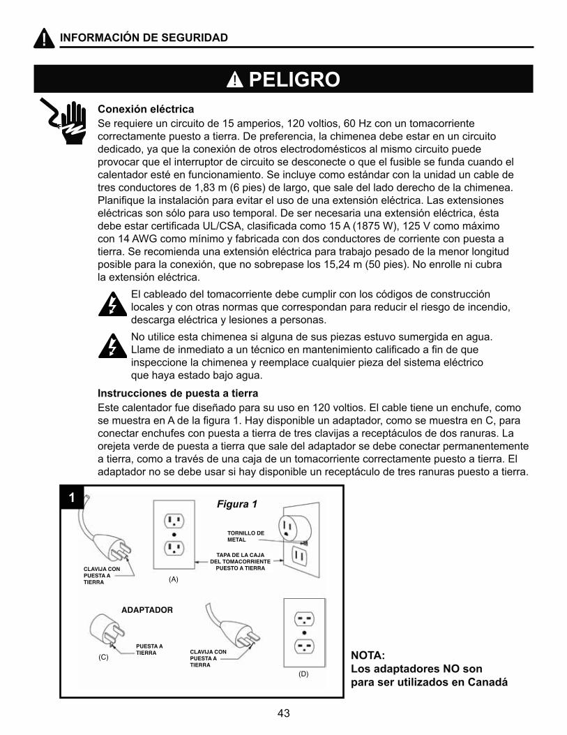
G���������������������$%������ "�$X]������� "��]�^_�������������������� correctamente puesto a tierra. De preferencia, la chimenea debe estar en un circuito dedicado, ya que la conexión de otros electrodomésticos al mismo circuito puede provocar que el interruptor de circuito se desconecte o que el fusible se funda cuando el calentador esté en funcionamiento. Se incluye como estándar con la unidad un cable de tres conductores de 1,83 m (6 pies) de largo, que sale del lado derecho de la chimenea. �������������� ������¯��������������� ��������'�� �¯������������>� �'�� ��� �eléctricas son sólo para uso temporal. De ser necesaria una extensión eléctrica, ésta ��� ���������������>?@G�"���� ������������$%���H$J�%�QV"�$X%�Y�������°'���� ����$Z��Q[�������®����������������������� ���������� ���������������� �����tierra. Se recomienda una extensión eléctrica para trabajo pesado de la menor longitud posible para la conexión, que no sobrepase los 15,24 m (50 pies). No enrolle ni cubra la extensión eléctrica.
El cableado del tomacorriente debe cumplir con los códigos de construcción locales y con otras normas que correspondan para reducir el riesgo de incendio, descarga eléctrica y lesiones a personas.
� }��������� ���������� ����������� � ��_� � ����� ���������������� � >�������������������������������������������������������������� � �� ����������������������������������_����� � ������������� que haya estado bajo agua.
Este calentador fue diseñado para su uso en 120 voltios. El cable tiene un enchufe, como ��� �������������������$��^����� �����������������"������ ��� ������@"�����conectar enchufes con puesta a tierra de tres clavijas a receptáculos de dos ranuras. La orejeta verde de puesta a tierra que sale del adaptador se debe conectar permanentemente a tierra, como a través de una caja de un tomacorriente correctamente puesto a tierra. El adaptador no se debe usar si hay disponible un receptáculo de tres ranuras puesto a tierra.
PELIGRO
NOTA: Los adaptadores NO son ������������ ������������
1
44
INFORMACIÓN DE SEGURIDAD
Control remoto
LAS LÍNEAS ELÉCTRICAS, DE PLOMERIA O DE GAS DEBEN ESTAR EN PARED.��� ���������"�������������������"�������� ��������_���¯���G�� ��� ����"�������contacto con su electricista, plomero o persona del servicio.
EL DAÑO DEL PRODUCTO PUEDE OCURRIR.Nunca intente desmontar o alterar el producto de cualquier manera no instruida por este manual.
Este dispositivo cumple con la sección 15 de las reglas de la FCC. El funcionamiento está sujeto a las siguientes dos condiciones: (1) este dispositivo no debe causar interferencia perjudicial, y (2) este dispositivo deberá aceptar cualquier interferencia recibida, incluida la interferencia que pudiese causar ��������¯������ �����< ���������� ������������� ��������������������������� ��®��� �para un dispositivo digital Clase B, conforme a la Parte 15 de las reglas de la FCC y con ICES-003 de ���=��� �������@����°��< �� ��®��� � �°���� ±��� ����������������������¯����_�������������������������;���������������� ������¯��� ���������< �����������"������_����������������energía de radiofrecuencia y, si no se instala y usa de acuerdo con el manual de instrucciones, puede causar interferencia perjudicial a las comunicaciones de radio.
G���������"���� ��������_�������� ��������°������������ ��������� ������¯���������������Si este equipo genera interferencia perjudicial a la recepción de radio o televisión, lo que se puede determinar al apagar y encender el equipo, se recomienda al usuario que intente corregir la interferencia con una o más de las siguientes medidas:
`� Reorientar o reubicar la antena de recepción.
`� Aumentar la separación entre el equipo y el receptor.
`� Conectar el equipo a un tomacorriente de un circuito distinto al que usa el receptor.
`� G���������������������� ���������������������������'��������������?&Y��
8����������������������������������������������������"#$#%'������������������
}|��_�������®� �������� ��������� ��NO use baterías recargables de plata-cadmio en la unidad de control remoto. }|��_�������®� ��������� "� �°�����H_���\�������V����������� �H�®����������V��NO incinere las baterías. Una eliminación incorrecta de las baterías puede provocar que � �� �'������� �������
�z<@��@=²}~�>� ������� �������������� ������� ����'� ������������ ������ � ����[^��[����=���"���@G�����®�������������������_���¯������ ������������� � ���������_��� �������
ALERTA
PRECAUCIÓN
45
CONTENIDO DEL PAQUETE
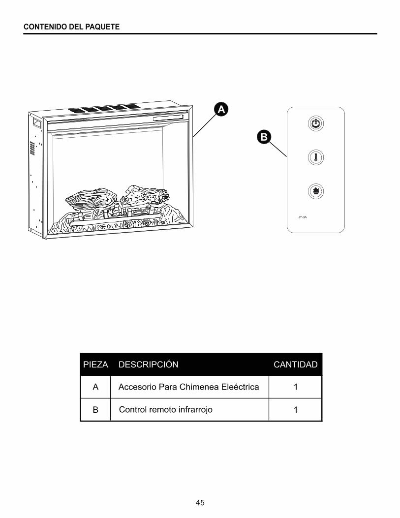
PIEZA DESCRIPCIÓN CANTIDAD
A 1
B 1
Accesorio Para Chimenea Eleéctrica
Control remoto infrarrojo
A
B
GHP
46
CONTENIDO DEL PAQUETE
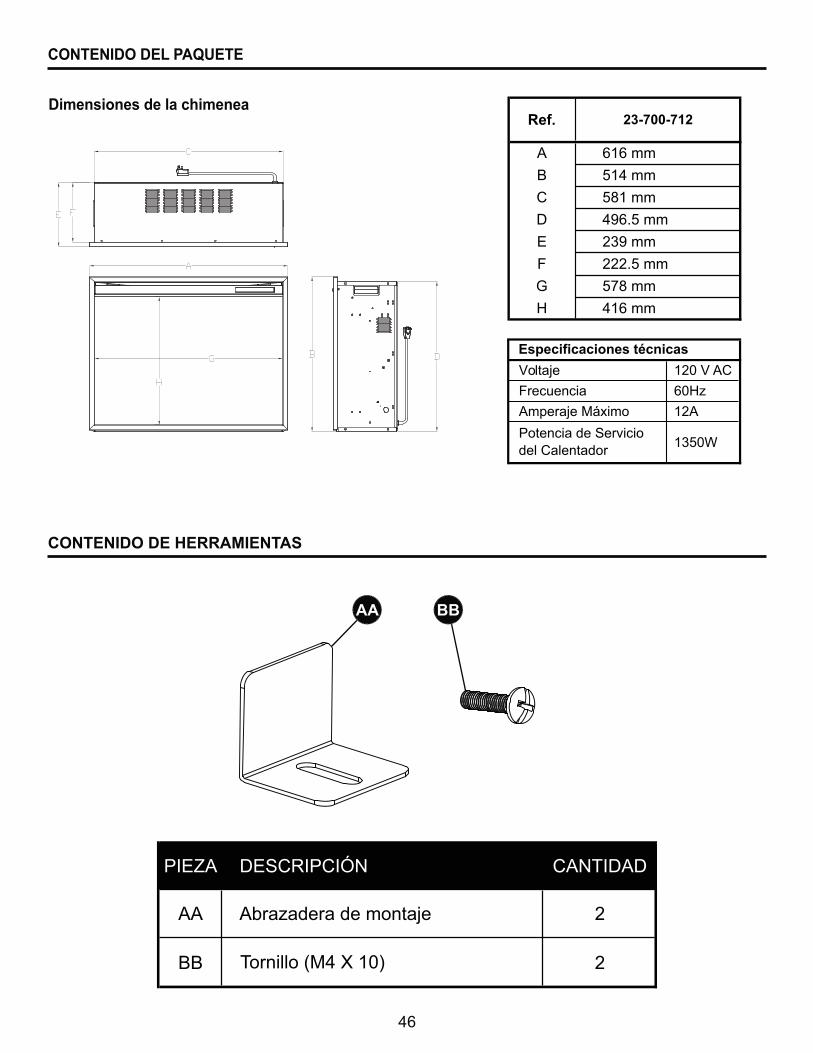
Dimensiones de la chimenea
AA BB
PIEZA DESCRIPCIÓN CANTIDAD
AA 2
BB 2
Abrazadera de montaje
Tornillo (M4 X 10)
CONTENIDO DE HERRAMIENTAS
Ref.
A 616 mm
B 514 mm
C 581 mm
D 496.5 mm
E 239 mm
F 222.5 mm
G 578 mm
H 416 mm
23-700-712
$X]�Y�AC
�]^_
12A
1350W
8�����(����������q������
Y�ltaje
Frecuencia
Amperaje Máximo
Potencia de Servicio del Calentador
47
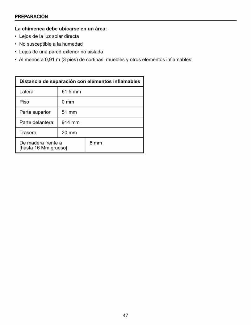
\������������������������������������������
Lateral 61.5 mm
Piso 0 mm
Parte superior 51 mm
Parte delantera 914 mm
Trasero 20 mm
De madera frente a 8 mm [hasta 16 Mm grueso]
`��>;� ��������_� �����������
`��}�� � �����������������
`��>;� �����������'����������� ����
`�������� ���]"�$���H��� V���������� "����� ������� ������ ���+�����
������������������������������^
PREPARACIÓN
48
DIRECTIVES D’INSTALLATION
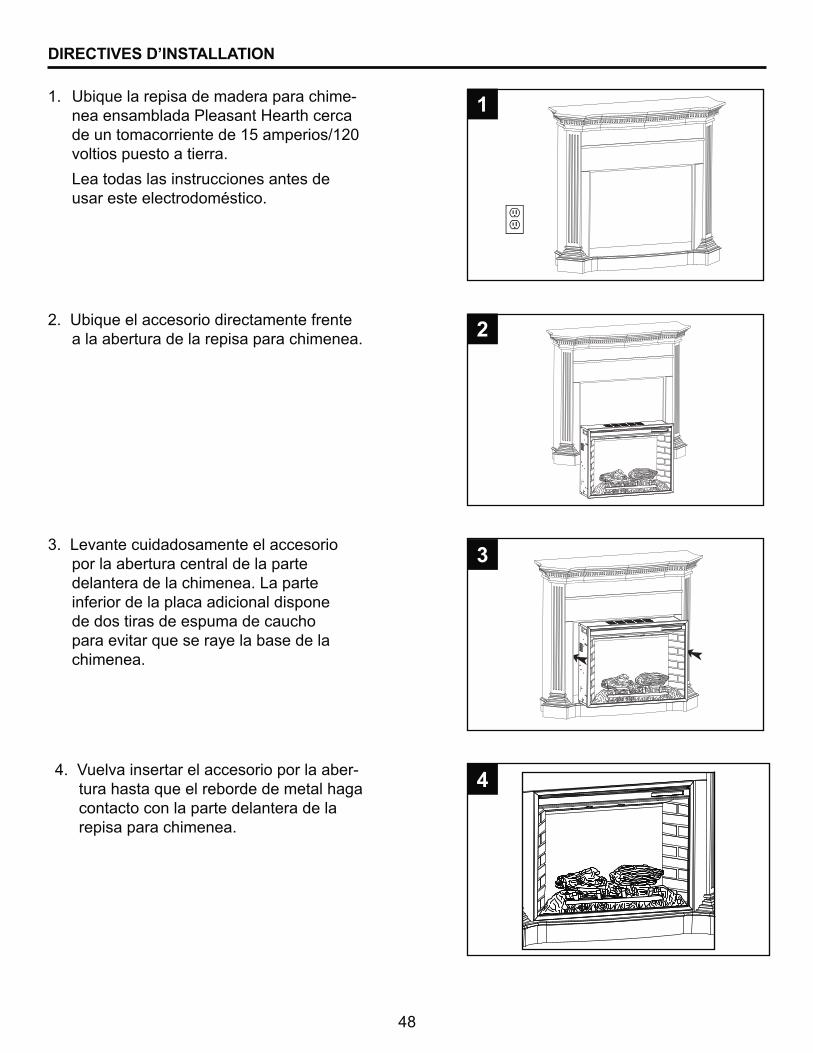
1. Ubique la repisa de madera para chime-���� ����������� ����^����������de un tomacorriente de 15 amperios/120 voltios puesto a tierra.
Lea todas las instrucciones antes de usar este electrodoméstico.
3. Levante cuidadosamente el accesorio por la abertura central de la parte delantera de la chimenea. La parte inferior de la placa adicional dispone de dos tiras de espuma de caucho para evitar que se raye la base de la chimenea.
2. Ubique el accesorio directamente frente a la abertura de la repisa para chimenea.
1
#
3
Z���Y������� ���������� ��������������-tura hasta que el reborde de metal haga contacto con la parte delantera de la repisa para chimenea.
4
49
DIRECTIVES D’INSTALLATION
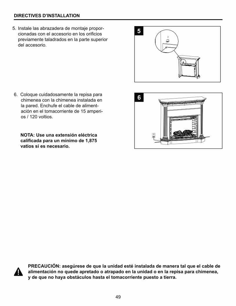
}"8�+<�@�Z^�������������������������q��������������������������������alimentación no quede apretado o atrapado en la unidad o en la repisa para chimenea, ��������������������������������������������������������
=� ������ �����_������������;�����-������� ���������� ��������� �������� �previamente taladrados en la parte superior del accesorio.
5. %
6. Coloque cuidadosamente la repisa para chimenea con la chimenea instalada en la pared. Enchufe el cable de aliment-ación en el tomacorriente de 15 amperi-os / 120 voltios.
6
Z[�+^<����������������q������������������������������)*%vatios si es necesario.
50
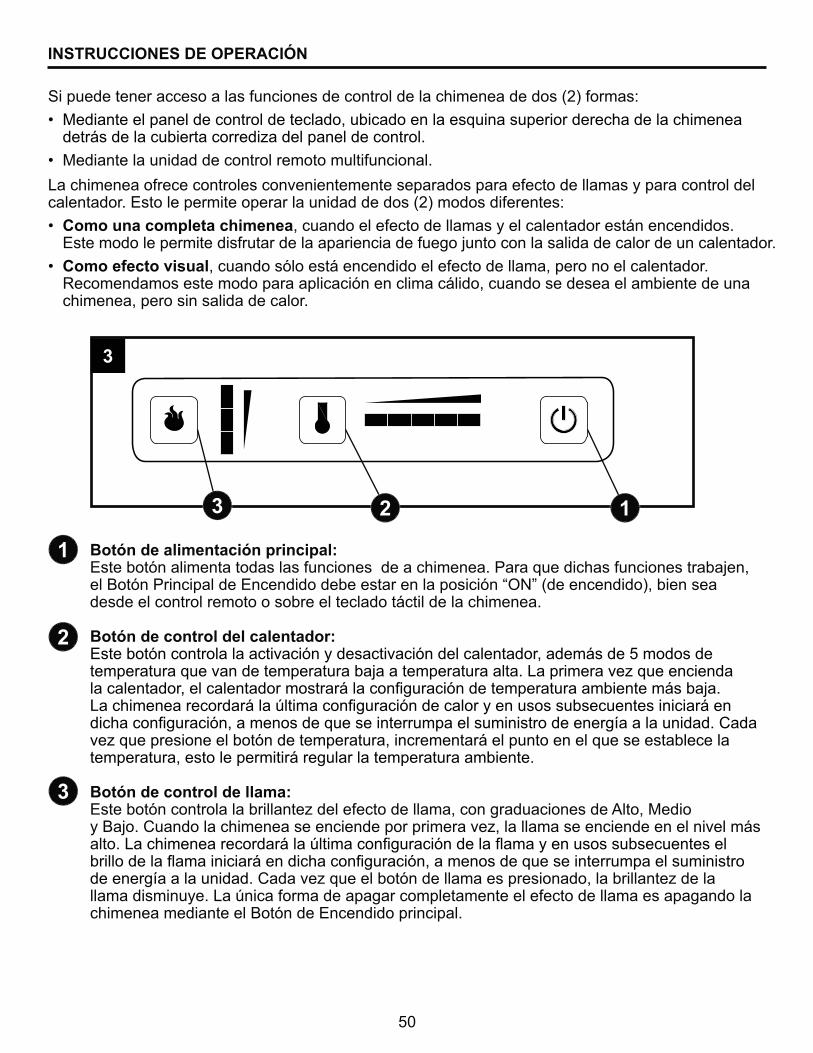
Botón de alimentación principal:Este botón alimenta todas las funciones de a chimenea. Para que dichas funciones trabajen, �����¯�������������<����������� ���������� ���¯��¨|}©�H���������V"����� ������desde el control remoto o sobre el teclado táctil de la chimenea.
Botón de control del calentador:Este botón controla la activación y desactivación del calentador, además de 5 modos de �����������������������������;�������������������>���������_�����������������������"��������������� ����°��������������¯���������������������° ���;���>����������������°����´����������������¯��������������� � � �� ���� ��������°�������������������¯�"������ ������ ������������ ����� ���������®���������������@�����_����� ���������¯������������"����������°��������������� � ���������temperatura, esto le permitirá regular la temperatura ambiente.
Botón de control de llama:< �����¯����������������������_����������������"��������������� �������"������ ����;���@���������������� �����������������_"���������� �����������������° �alto. >����������������°����´����������������¯�������+��������� � � �� ���� ���������������+�����������°�������������������¯�"������ ������ ������������ ����� ����de energía a la unidad. @�����_���������¯���������� �� ������"������������_������llama disminuye. La única forma de apagar completamente el efecto de llama es apagando la chimenea mediante el Botón de Encendido principal.
INSTRUCCIONES DE OPERACIÓN
La chimenea ofrece controles convenientemente separados para efecto de llamas y para control del calentador. Esto le permite operar la unidad de dos (2) modos diferentes:
`� Como una completa chimenea, cuando el efecto de llamas y el calentador están encendidos. Este modo le permite disfrutar de la apariencia de fuego junto con la salida de calor de un calentador.
`� Como efecto visual, cuando sólo está encendido el efecto de llama, pero no el calentador. Recomendamos este modo para aplicación en clima cálido, cuando se desea el ambiente de una chimenea, pero sin salida de calor.
Si puede tener acceso a las funciones de control de la chimenea de dos (2) formas:
`� Mediante el panel de control de teclado, ubicado en la esquina superior derecha de la chimenea ���° ��������������������_�������������������
`� �������������������������������������������������
1
#
3
# 13
3
51
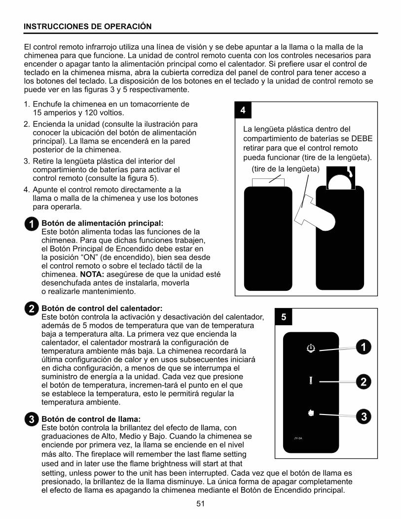
<������������������������;�������_�������®������� �¯���� ��������������������������������������chimenea para que funcione. La unidad de control remoto cuenta con los controles necesarios para encender o apagar tanto la alimentación principal como el calentador. G������� ������������������������������������ ��"�����������������������_������������������������������ ����los botones del teclado. La disposición de los botones en el teclado y la unidad de control remoto se ���������� ������ �����%�� ���������
1. Enchufe la chimenea en un tomacorriente de 15 amperios y 120 voltios.
2. Encienda la unidad (consulte la ilustración para conocer la ubicación del botón de alimentación principal). La llama se encenderá en la pared posterior de la chimenea.
3. Retire la lengüeta plástica del interior del compartimiento de baterías para activar el ��������������H��� �������������%V�
4. Apunte el control remoto directamente a la llama o malla de la chimenea y use los botones para operarla.
Botón de alimentación principal:Este botón alimenta todas las funciones de la chimenea. Para que dichas funciones trabajen, el Botón Principal de Encendido debe estar en ���� ���¯��¨|}©�H���������V"����� ��� ��el control remoto o sobre el teclado táctil de la chimenea. NOTA: asegúrese de que la unidad esté desenchufada antes de instalarla, moverla ������_����������������
Botón de control del calentador:Este botón controla la activación y desactivación del calentador, además de 5 modos de temperatura que van de temperatura ��;�������������������>���������_�����������������������"��������������� ����°��������������¯����temperatura ambiente más baja. La chimenea recordará la ´����������������¯��������������� � � �� ���� ��������°�������������������¯�"������ ������ ������������ ����� ���������®���������������@�����_����� ����el botón de temperatura, incremen-tará el punto en el que se establece la temperatura, esto le permitirá regular la temperatura ambiente.
Botón de control de llama:< �����¯����������������������_����������������"����� graduaciones de Alto, Medio y Bajo. Cuando la chimenea se ����������������_"���������� ����������������más alto. &������������������������ ��+��� ������� ��������������� ����+���������� ������ �������������setting, unless power to the unit has been interrupted. @�����_���������¯���������� �� ������"������������_�������������� �������>��´�����������������������������el efecto de llama es apagando la chimenea mediante el Botón de Encendido principal.
La lengüeta plástica dentro del compartimiento de baterías se DEBEretirar para que el control remoto pueda funcionar (tire de la lengüeta).
#
3
1
INSTRUCCIONES DE OPERACIÓN
1
#
3
(tire de la lengüeta)
4
%
52
>���_�
>���_���������������������������"�������������� ������ ���������������������������° ��������������������_������������������"� ��������_��� ¯���� ���������±�� ���"�levemente humedecido con agua (si es necesario, se puede agregar una pequeña cantidad de ;��¯���������� ��������V��� ���� ����� ���������±�� ���� ����>������_��������� �������������� ��������_���� ����� ¯��������������±�� ����� � ��}|�� �����´��������������� �����abrasivo, ya que estos productos dañan los controles del teclado y el difusor de la malla.
Información sobre el vidrio
1. Bajo ninguna circunstancia este producto se debe operar con el vidrio roto.
2. No golpee el vidrio.
3. No use limpiadores abrasivos para limpiar el vidrio.
Z�� < ����������� �����������������<������_��������������������������������������������������������������������� ���������� ¯����������_��������������������������
CUIDADO Y MANTENIMIENTO
+������������������� ���<+�;<@8"�������������^
1. Apague la unidad.
2. Desenchufe el cable de alimentación del tomacorriente.
3. Deje que la chimenea se enfríe si ha estado funcionando.
Mantenimiento de los motores
]����������������������������q��������������������q������������������������������(��������������������������������������������
Los motores usados en el calentador de ventilador y el soplador de llamas vienen lubricados previamente para prolongar la vida útil de los rodamientos y no necesitan otra lubricación. Sin ������"� ������������������_����� �����¯����¯����������������� ���������������la entrada y salida de aire, así como del calentador de ventilador. Para un uso pesado o continuo, �������_����¯����� ��������_�����������������������G�������������� ����������������aire frío y cálido, compruebe que el ventilador se mueva libremente y que no haya desechos que �� ���������+�;���������G����������������� ������������"����������� ������������������������ ��������_���������������������������±� �������������
53
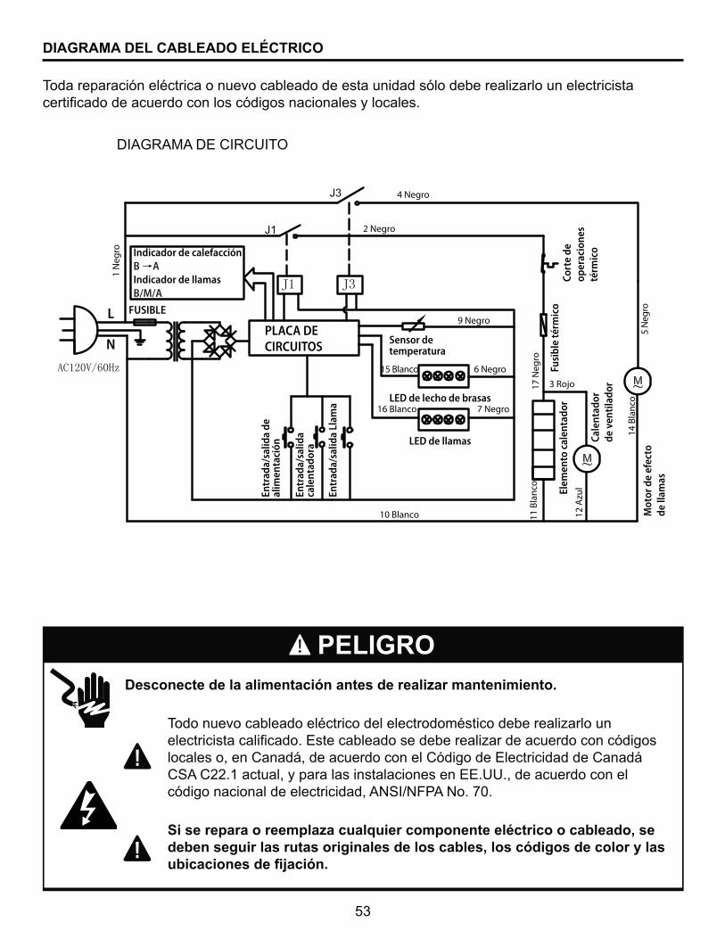
\������������������������������������� ����������������
� &�������������������������������������� ������������_�������� � ������� ��������������< ���������� ��������_�����������������¯���� � locales o, en Canadá, de acuerdo con el Código de Electricidad de Canadá CSA C22.1 actual, y para las instalaciones en EE.UU., de acuerdo con el código nacional de electricidad, ANSI/NFPA No. 70.
]����������������� ����������������������q������������������ deben seguir las rutas originales de los cables, los códigos de color y las ��������������������
PELIGRO
&����������¯���������������������������� ���������� ¯����������_��������������� ���������������������������� ��¯���� ��������� �������� �
*=�[z����*<�@=z@�=&|�
DIAGRAMA DEL CABLEADO ELÉCTRICO
PLACA DE CIRCUITOS
Indicador de calefacciónB AIndicador de llamasB/M/A
FUSIBLE
1 N
egro
2 Negro
4 Negro
9 Negro
15 Blanco 6 Negro
7 Negro16 Blanco
10 Blanco
17 N
egro
11 B
lanc
o
12 A
zul
3 Rojo
14 B
lanc
o5
Neg
roL
N
Entr
ada/
salid
a de
alim
enta
ción
Entr
ada/
salid
a ca
lent
ador
a
Entr
ada/
salid
a Ll
ama
Sensor de temperatura
LED de lecho de brasas
LED de llamas
Elem
ento
cal
enta
dor
Fusi
ble
térm
ico
Cort
e de
op
erac
ione
s té
rmic
oCa
lent
ador
de
ven
tila
dor
Mot
or d
e ef
ecto
de
llam
as
54
SOLUCIÓN DE PROBLEMAS
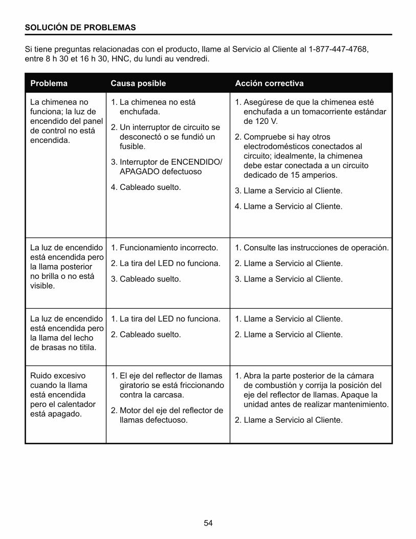
Si tiene preguntas relacionadas con el producto, llame al Servicio al Cliente al 1-877-447-4768,����J����]���$�����]"�^}@"��������������������
Problema Causa posible Acción correctiva
La chimenea no ���������������_���encendido del panel de control no está encendida.
>����_�����������está encendida pero la llama posterior no brilla o no está visible.
>����_�����������está encendida pero la llama del lecho de brasas no titila.
Ruido excesivo cuando la llama está encendida pero el calentador está apagado.
1. La chimenea no está enchufada.
2. Un interruptor de circuito se desconectó o se fundió un fusible.
3. Interruptor de ENCENDIDO/���[�*|������� �
4. Cableado suelto.
1. Funcionamiento incorrecto.
2. La tira del LED no funciona.
3. Cableado suelto.
1. La tira del LED no funciona.
2. Cableado suelto.
$��<��;�����+������������ �giratorio se está friccionando contra la carcasa.
X�����������;�����+�������llamas defectuoso.
1. Asegúrese de que la chimenea esté enchufada a un tomacorriente estándar ��$X]�Y�
2. Compruebe si hay otros electrodomésticos conectados al circuito; idealmente, la chimenea debe estar conectada a un circuito dedicado de 15 amperios.
3. Llame a Servicio al Cliente.
4. Llame a Servicio al Cliente.
1. Consulte las instrucciones de operación.
2. Llame a Servicio al Cliente.
3. Llame a Servicio al Cliente.
1. Llame a Servicio al Cliente.
2. Llame a Servicio al Cliente.
1. Abra la parte posterior de la cámara de combustión y corrija la posición del ;�����+������������ �������������������� �������_���������������
2. Llame a Servicio al Cliente.

55
SOLUCIÓN DE PROBLEMAS
Si tiene preguntas relacionadas con el producto, llame al Servicio al Cliente al 1-877-447-4768,����J����]���$�����]"�^}@"��������������������
Problema Causa posible Acción correctiva
Ruido excesivo cuando el calentador está funcionando.
El calentador no funciona.
1. Soplador sucio u obstruido.
2. Ensamble del calentador defectuoso.
1. Funcionamiento incorrecto.
2. Interruptor del calentador defectuoso.
3. Ensamble del calentador defectuoso.
4. Cableado suelto.
5. ������������_�� ����������obstruida.
1. Consulte la sección Mantenimiento de los motores del manual de instrucciones.
2. Llame a Servicio al Cliente.
1. Consulte las instrucciones de operación.
2. Llame a Servicio al Cliente.
3. Llame a Servicio al Cliente.
4. Llame a Servicio al Cliente.
5. Desenchufe la unidad. Limpie el polvo y los desechos del área de la puerta. Espere cinco minutos, vuelva a enchu-far la unidad y encienda el calentador.
56
<�������������������_����� ��������������������������� ����°������ ������������¯��ni materiales durante un período de un año a partir de la fecha de compra, siempre y cuando se cumplan las siguientes condiciones y limitaciones.
1. Esta chimenea eléctrica se debe instalar y operar en todo momento de acuerdo con las instrucciones de instalación y operación proporcionadas con el producto. Cualquier alteración, abuso deliberado, accidente o uso inadecuado del producto anulará esta garantía.
2. Esta garantía no es transferible y sólo está disponible para el propietario original, siempre y ���������������� ����������_����������� �������������������_���������@���±®��
��� < ���������®�� �������������������¯��������_�����_� ���� ���� ����������� � ������������������������"� ��������������������_������� ����� ������������������ ������� ���� ���� ������"�� �� ������������ ���¯��������������@���±®���������dicho defecto.
4. La Compañía podrá, bajo su criterio, eximirse de toda obligación respecto de esta garantía ����� ������������������������������_�������� ��
5. Esta garantía no cubrirá ningún costo de instalación, mano de obra, construcción, transporte ���������������� ��;��������_�������� �"� ��������¯�"�����_��������� ������¯�"������Compañía no asumirá ninguna responsabilidad por las mismas. La Compañía tampoco será responsable por ningún daño accidental, indirecto o resultante, salvo que la ley estipule lo contrario.
6. Mediante el presente, se excluye expresamente cualquier otra garantía, expresa o implícita, respecto del producto, sus componentes y accesorios, o cualquier otra obligación o responsabilidad de parte de la Compañía.
��� >��@���±®������ ��"����������_��������´����������� ������� �������"��������������responsabilidad respecto de la venta de este producto.
8. Las garantías descritas en este documento no se aplican a accesorios que no sean de el fabricante y que se usen junto con la instalación de este producto.
8�������������������^
�V� >����������������������������¯ ��� ������������ ����������"�+´��������� � � ������ �químicas dañinas.
b) La chimenea está sometida a períodos prolongados de humedad o condensación.
c) Se produce cualquier alteración, abuso deliberado, accidente o uso inadecuado del producto.
SI SE NECESITA SERVICIO DE GARANTÍA. . .
1) Póngase en contacto el fabricante con el Servicio al Cliente de al 1-877-447-4768,� ����J����]���$�����]"�^}@"���������������������� �´� ������� ��������®�"� ��������
de venta y el modelo o número de serie de su producto el fabricante.
XV� }|�=}&<}&<�z<�>= �z�}=}[µ}�&z���¶|�*<�z<��z�@=²}��G&<*��=G�|�
GARANTÍA
GHP Group, Inc.8280 Austin Avenue�������[���"�=>�60053-3207
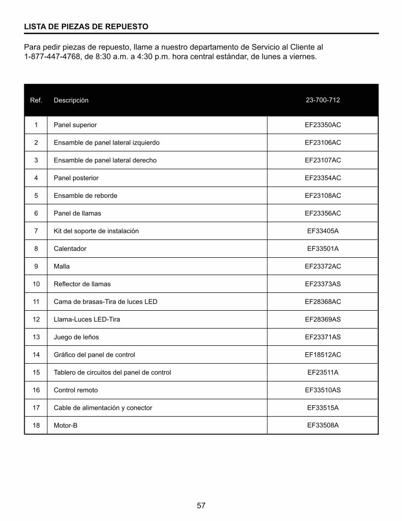
57
LISTA DE PIEZAS DE REPUESTO
����������_� ����� ��"���������� ����������������G����������@������� 1-877-447-4768, de 8:30 a.m. a 4:30 p.m. hora central estándar, de lunes a viernes.
Ref. Descripción
1 Panel superior
2 Ensamble de panel lateral izquierdo
3 Ensamble de panel lateral derecho
4 Panel posterior
5 Ensamble de reborde
6 Panel de llamas
7 Kit del soporte de instalación
8 Calentador
9 Malla
10 Reflector de llamas
11 Cama de brasas-Tira de luces LED
12 Llama-Luces LED-Tira
13 Juego de leños
14 Gráfico del panel de control
15 Tablero de circuitos del panel de control
16 Control remoto
17 Cable de alimentación y conector
18 Motor-B
EF23108AC
EF23356AC
EF33508A
EF33405A
EF33501A
EF23372AC
EF23373AS
EF28368AC
EF28369AS
23-700-712
EF23371AS
EF18512AC
EF23511A
EF33510AS
EF33515A
EF23350AC
EF23106AC
EF23107AC
EF23354AC
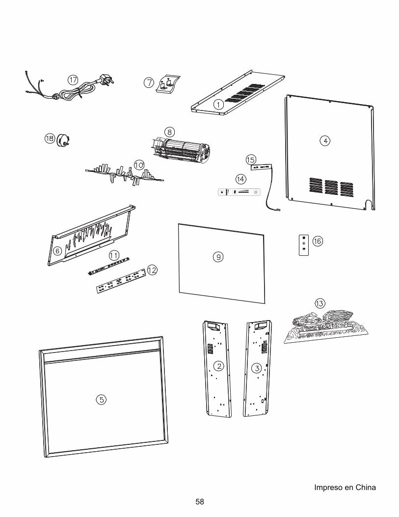
58
Impreso en China