electric log splitter
TRANSCRIPT

12 x 20 Log SplitterLS 8000 Type II
Instruction Manual

2
TABLE OF CONTENTS
SAFETY INSTRUCTIONS ......................................... 3,4
ELECTRICAL CONNECTIONSPower Source ............................................................5Extension Cords ........................................................ 5Grounding Instructions .............................................. 5
UNPACKING MACHINE ............................................... 6
ASSEMBLY INSTRUCTIONSInstalling Leg Assembly ............................................. 7Attaching Operating Lever ......................................... 7Attaching Wheel Bracket ...........................................7,8
OPERATING CONTROLS, MAINTENANCE,AND ADJUSTMENTS
Starting and Stopping Machine Cycle .......................8Maintaining Proper Oil Level ..................................... 8Adjusting Air Bleed Screw ......................................... 9
OPERATION, SHIPPING, AND STORAGESplitting a Log ............................................................9Transporting and Storing Log Splitter ........................9
PARTS LIST ............................................................................. 10,11
WARRANTY ............................................................................. 12

3
SAFETY RULES
1. For your own safety, read instruction manual beforeoperating the tool. Learn the tool’s application and limitationsas well as the specific hazards peculiar to it.
2. Keep guards in place and in working order.3. Always wear eye protection. Wear safety glasses. Everydayeyeglasses only have impact resistant lenses; they are not safetyglasses. Also use face or dust mask if cutting operation is dusty.These safety glasses must conform to ANSI Z87.1 requirements.Note: Approved glasses have Z87 printed or stamped on them.4. Remove adjusting keys and wrenches. Form a habit ofchecking to see that keys and adjusting wrenches are removedfrom tool before turning it “ON”.5. Keep work area clean. Cluttered areas and benches inviteaccidents.6. Don’t use in dangerous environment. Don’t use power toolsin damp or wet locations, or expose them to rain. Keep workarea well-lighted.7. Keep children and visitors away. All children and visitorsshould be kept a safe distance from work area.8. Make workshop childproof – with padlocks, masterswitches, or by removing starter keys.9. Don’t force tool. It will do the job better and safer at the ratefor which it was designed.10. Use the right tool. Don’t force tool or attachment to do a jobfro which it was not designed.11. Wear proper apparel. No loose clothing, gloves, neckties,rings, bracelets, or other jewelry to get caught in moving parts.Nonslip hard-toed footwear is recommended. Wear protectivehair covering to contain long hair.12. Don’t overreach. Keep proper footing and balance at all times.13. Maintain tools in top condition. Keep tools sharp andclean for best and safest performance. Follow instructions forlubricating and changing accessories.14. Disconnect tools before servicing.
15. Never stand on tool. Serious injury could occur if the tool istipped or if the cutting tool is accidentally contacted.16. Check damaged parts. Before futher use of the tool, aguard or other part that is damaged should be carefully checkedto ensure that it will operate properly and perform its intendedfunction - check for alignment of moving parts, binding of movingparts, breakage of parts, mounting, and any other conditions thatmay affect its operation. A guard or other part that is damagedshould be properly repaired or replaced.17. Stay alert, watch what you are doing, and use commonsense when operating a power tool. Do not use tool whiletired or under the influence of drugs, alcohol, or medication .A moment of inattentioin while operating power tools may resultin serious personal injury.18. Make sure tool is disconnected from power supply whilemotor is being mounted, connected or reconnected.19. WARNING: Some dust created by power sanding,sawing, grinding, drilling, and other construction activitiescontains chemicals known to cause cancer, birth defects or otherreproductive harm. Some examples of these chemicals are:• Lead from lead-base paints• Crystalline silica form bricks and cement and other masonry products.• Arsenic and chromium from chemically-treated lumber.Your risk from these exposures varies, depending on how oftenyou do this type of work. To reduce your exposure to thesechemicals: work in a well ventilated area, and work withapproved safety equipment, such as those dust masks that arespecially designed to filter out microscopic particles.
SAVE THESE INSTRUCTIONSRefer to them often and use them to instruct others.
WARNING: FAILURE TO FOLLOW THESE RULES MAY RESULT IN SERIOUS PERSONAL INJURY.
As with all machinery there arecertain hazards involved with operationand use of this machine. Using themachine with respect and caution willconsiderably lessen the possibility ofpersonal injury. However, if normalsafety precautions are overlooked orignored, personal injury to the
operator may result. This machinewas designed for certain applicationsonly. Fisch strongly recommends thatthis machine NOT be modified and/orused for any application other thanfor which it was designed. If youhave any questions relative to aparticular application, DO NOT use
the machine until you have firstcontacted Fisch to determine if it canor should be performed on the product.
Fisch Precision Tools Inc.Route 40 WestP.O. Box 644Claysville, PA 15323

4
ADDITIONAL SAFETY RULES FOR LOG SPLITTERS
WARNING: DO NOT OPERATE YOUR LOG SPLITTER UNTIL IT IS COMPLETELYASSEMBLED AND INSTALLED ACCORDING TO THE INSTRUCTIONS.
1. If you are not thoroughly familiar with the operation ofa log splitter, obtain advice from your supervisor, instructoror other qualified person.2. Make sure wiring codes and recommended electricalconnection instructions are followed, and that the machineis properly grounded.3. Make all adjustments with the power off.4. Machine must be positioned on a solid work surfacebefore using.5. Do not split wood larger than the recommendedcapacity. If jam should occur, release motor switchbutton and use pry bar to remove jammed log.NEVER use your hands.
6. Do not try to remove split logs until the unit has totallycompleted work cycle.7. Stack logs as you work. This will provide a safer,uncluttered work area.8. Disconnect machine from the power source whenmaking repairs.9. Replace all guards after servicing.10. Before leaving the machine, make sure the work areais clean.
5
ELECTRICAL CONNECTIONSPower SourceA seperate electrical circuit should be used for your tool. This circuit should not be less than #12wire and should be protected with a 20 amp time lag fuse. Before connecting the motor to the powerline, make sure the switch is in the “OFF” position and be sure the electric current is of the samecharacteristics as indicated on the tool. All line connections should make good contact. Running onlow voltage will damage the motor.
WARNING: THIS TOOL MUST BE GROUNDED WHILE IN USE TO PROTECT THEOPERATOR FROM ELECTRIC SHOCK.
Grounding Instructions
WARNING: DO NOT EXPOSE THE TOOL TO RAIN OR OPERATE IN DAMP LOCATIONS.
All grounded, cord-connected tools:In the event of a malfunction or breakdown, grounding provides a path of least resistance for electricshock. This tool is equipped with an electric cord having an equipment-grounding conductor and agrounding plug. The plug must be plugged into a matching outlet that is properly installed andgrounded in accordance with all local codes and ordinances. Do not modify the plug provided - if itwill not fit the outlet, have the proper outlet installed by a qualified electrician.Improper connection of the equipment-grounding conductor can result in risk of electric shock. Theconductor with insulation having an outer surface that is green with or without yellow stripes is theequipment-grounding conductor. If repair or replacement of the electric cord or plug is necessary, donot connect the equipment grounding conductor to a live terminal. Check with a qualified electricianor service personnel if the grounding instructions are not completely understood, or if in doubt as towhether the tool is properly grounded.
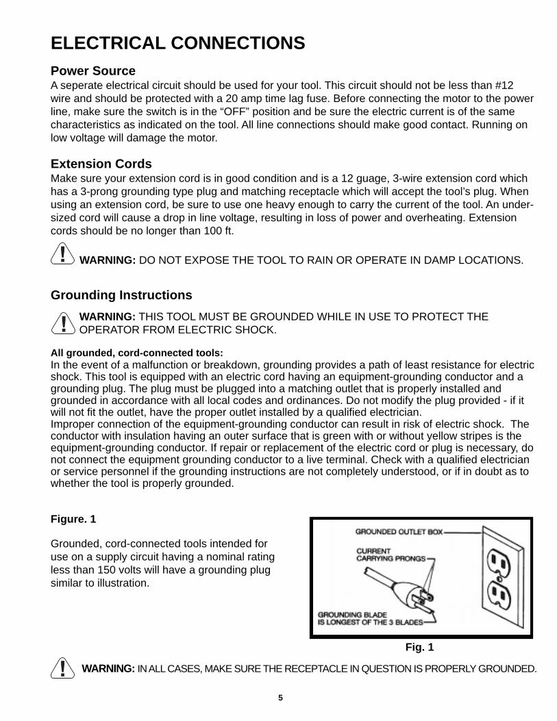
Figure. 1
Grounded, cord-connected tools intended foruse on a supply circuit having a nominal ratingless than 150 volts will have a grounding plugsimilar to illustration.
WARNING: IN ALL CASES, MAKE SURE THE RECEPTACLE IN QUESTION IS PROPERLY GROUNDED.
Fig. 1
Extension CordsMake sure your extension cord is in good condition and is a 12 guage, 3-wire extension cord whichhas a 3-prong grounding type plug and matching receptacle which will accept the tool’s plug. Whenusing an extension cord, be sure to use one heavy enough to carry the current of the tool. An under-sized cord will cause a drop in line voltage, resulting in loss of power and overheating. Extensioncords should be no longer than 100 ft.

6
Figure. 2
Fig. 2
1. Basic Unit and Motor2. Operating Lever3. Hex Head Screws (2)
and Lock Nuts (2)4. Support Leg Assembly
5. Assembly/Adjustment Wrenches (2)6. Wheel Bracket, Axle, and Wheels (2)
UNPACKING THE MACHINECarefully unpack the Log Splitter from the shipping container. Check to see that you have all of thefollowing items. Do not turn the machine ON if any of these items are missing. You may cause injuryto yourself and / or damage the machine.
7
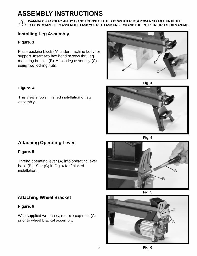
Installing Leg Assembly
Figure. 3
Place packing block (A) under machine body forsupport. Insert two hex head screws thru legmounting bracket (B). Attach leg assembly (C).using two locking nuts.
Figure. 4
This view shows finished installation of legassembly.
Figure. 5
Thread operating lever (A) into operating leverbase (B). See (C) in Fig. 6 for finishedinstallation.
Figure. 6
With supplied wrenches, remove cap nuts (A)prior to wheel bracket assembly.
Fig. 3
Fig. 4
Fig. 5
Fig. 6
Attaching Operating Lever
Attaching Wheel Bracket
ASSEMBLY INSTRUCTIONSWARNING: FOR YOUR SAFETY, DO NOT CONNECT THE LOG SPLITTER TO A POWER SOURCE UNTIL THETOOL IS COMPLETELY ASSEMBLED AND YOU READ AND UNDERSTAND THE ENTIRE INSTRUCTION MANUAL.

8
Fig. 7
Fig. 8
Fig. 9
Fig. 10
Figure. 7
Mount wheel bracket assembly on the log splitterand attach using the two cap nuts (A). Tightenwith supplied wrenches.
Figure. 8
To start the cycle, depress the motor start switch(A). When the motor is up to speed, depress theoperating lever (B). The log ram (C) will push thelog into splitting wedge. To complete the cycle,release lever (B) until ram retracts. Then releasemotor switch (A).
OPERATING CONTROLS,MAINTENANCE ANDADJUSTMENTS
Figure. 9
With log splitter raised 90 degrees to the worksurface, unscrew the dip stick (A) and remove.
Figure. 10
Clean the dip stick and insert in oil cylinder (A).Remove again and make sure oil level is athigh mark or above (B) on the dip stick. If unitneeds oil, use only clean, high quality hydraulicoil specifically made for this type of use (such asNAPA).
Starting and Stopping Machine Cycle
Maintaining Proper Oil Level
NOTE: As with all hydraulic equiptment, acertain amount of oil seepage is common. Donot be alarmed if this is noticed. This oil assuresthat the ram and other components are properlylubricated during operation and storage. Alwayscheck oil level before using splitter.

9
Fig. 11
Fig. 12
Fig. 13
Fig. 14
Figure. 11
Before operating the log splitter, loosen thebleed screw (A) three to four turns. Retightenbleed screw before moving or storing log splitterto avoid oil leakage.
Figure. 12
The log splitting operation requires use of bothhands on the controls, keeping them away fromthe splitting action. Load a log, no larger than12” x 20”, onto the log guides (A) and up againstthe splitting wedge (B).
OPERATION, SHIPPING,AND STORAGE
Figure. 13
When it is safe to do so, depress the motor startswitch (A) with one hand. Wait until the motor isup to speed, then depress the operating lever(B). The log ram (C) will make contact with thelog and compress it against the wedge.NOTE: Both hands are on the controls.
Figure. 14
This view shows the wedge (A) splitting log inhalf. Once the log is split, release the operatinghandle and the motor start switch. The log ramwill retract.
Adjusting Air Bleed Screw
Splitting a Log
Retighten bleed screw as per Fig. 11. It is alsorecommended that you remove the operatinglever to avoid breakage.
Transporting and Storing Log Splitter

10
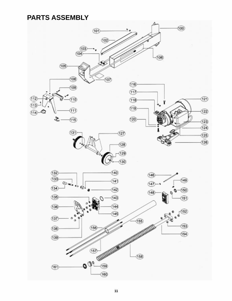
REF. NO. DESCRIPTION QTY.
100 MAIN BODY 1
101 FLAT WASHER (8MM) 4
102 LOG GUIDING PLATE 2
103 SOC HD CAP SCR M8 X 10MM 4
104 PLASTIC SLEEVE PLATE 2
105 WARNING LABEL 1
106 NAMEPLATE 1
107 LOG PUSHER ASSEMBLY 1
108 NUT (M6) 2
109 CR-HEAD SCREW (M6 X 20) 2
110 CARRY HANDLE 1
111 SUPPORT LOG 1
112 BOLT (M6 X 14) 2
113 NUT (M6) 4
114 RUBBER FOOT 1
115 RUBBER FOOT 1
116 BOLT (M8 X 25) 4
117 O-RING OIL SEAL 2
118 PUMP BRACKET 1
119 FLAT WASHER (8MM) 3
120 SPRING WASHER (8MM) 3
121 MOTOR/PUMP ASSEMBLY 1
122 SWITCH ASSEMBLY 1
123 ELECTRICAL BOX 1
124 POWER CORD 1
125 SCREW 4
126 MOTOR FOOT 1
127 WHEEL FRAME 1
128 RUBBER WHEEL 2
129 FLAT WASHER (M10) 2
130 END CAP 2
REF. NO. DESCRIPTION QTY.
131 SPRING WASHER (8MM) 2
132 HAND BAR 1
133 HAND BAR 1
134 HANDLE KNOB 1
135 COPPER WASHER 4
136 SUPPORT PLATE 1
137 NUT (M10) 4
138 NUT (M10) 4
139 FLAT WASHER (M10) 6
140 HANDLE BASE 1
141 INNER HEX NUT (M8 X 10) 1
142 SPRING 1
143 O-RING OIL SEAL 1
144 VALVE BODY KIT 1
145 CONTROL VALVE ASSEMBLY 1
146 DIP STICK 1
147 OIL SEAL 1
148 OIL CYLINDER COVER-END 1
149 BLEED SCREW (M4) 1
150 SEAL O-RING 1
151 SEAL O-RING 1
152 HEX NUT 2
153 HEX NUT 4
154 PISTON RAM 1
155 CYLINDER BODY 1
156 HEAD BOLT (SHORT) 2
157 HEAD BOLT (LONG) 2
158 SPRING 1
159 O-RING OIL SEAL 1
160 PISTON 1
161 U-PACKING 1
PARTS LIST
11
PARTS ASSEMBLY

WARRANTY
Fisch will repair or replace, at its discretion, any items that are defective innormal use for a period of 1 year. Fisch will not be responsible for any damageincurred while using this machine other than under normal use and in accordancewith the instructions provided in this Owners Manual. This warranty is Fisch’sonly warranty. Any other warranties expressed or implied are null and void.
One Year Warranty
Please direct any questions or comments to:Fisch Precision Tools Inc.
Route 40 WestP.O. Box 644
Claysville, PA 15323Phone: (724) 663-9072
Fax: (724) 663-9065
E-Mail: [email protected]