electric machines i - philadelphia university...polarity of a transformer consider a 220/110v...
TRANSCRIPT

Electric Machines I Three Phase Transformers
1
Dr. Firas Obeidat

2
Table of contents
1 • Introduction
2 • Wye-Wye Connection
3 • Wye-Delta Connection
4 • Delta-Wye Connection
5 • Delta-Delta Connection
6 • Polarity of a Transformer
7
• Parallel Operation of Transformers
8 • Transformer Vector Group
Dr. Firas Obeidat Faculty of Engineering Philadelphia University

3 Dr. Firas Obeidat Faculty of Engineering Philadelphia University
Introduction
A three-phase power transformer is used at the
power generating station to step-up the voltage.
Whereas in the power distribution substation,
the three-phase voltage is again stepped down
through a three-phase distribution transformer.
A three-phase transformer can be made either
by three windings wound on a common core or
by three single-phase transformer connected
together in a three-phase bank.
The first approach is a cheaper one that results
in a transformer with smaller size and less
weight. The main disadvantage of the first
approach is that if one phase becomes defective,
then the whole transformer needs to be
replaced. Whereas in the second approach, if
one of the transformers becomes defective then
the system can be given power by an open delta
at a reduced capacity. In this case, the defective
transformer is normally replaced by a new one.

4 Dr. Firas Obeidat Faculty of Engineering Philadelphia University
Introduction
The primary and secondary windings of the transformer may be connected
in either by wye (Y) or delta (Δ).
Three-phase transformer connections
Y-Y
(Wye-Wye)
Y-Δ
(Wye-Delta)
Δ-Y
(Delta-Wye)
Δ-Δ
(Delta-Delta)

5 Dr. Firas Obeidat Faculty of Engineering Philadelphia University
Wye-Wye Connection
At the primary side, the phase voltage can be written as,
At the secondary side, the phase voltage can be written as,
The ratio of the primary
line voltage to the
secondary line voltage of
this connection is,

6 Dr. Firas Obeidat Faculty of Engineering Philadelphia University
Wye-Wye Connection
The Y- Y connection has two very serious problems
1) If loads on the transformer circuit are unbalanced, then the voltages on
the phases of the transformer can become severely unbalanced.
2) Third-harmonic voltages can be large.
If a three-phase set of voltages is applied to a Y- Y transformer, the voltages
in any phase will be 120o apart from the voltages in any other phase.
However, the third-harmonic components of each of the three phases will be
in phase with each other. There are always some third-harmonic components
in a transformer because of the nonlinearity of the core, and these
components add up. The result is a very large third-harmonic component of
voltage on top of the 50-ar 60-Hz fundamental voltage. This third-harmonic
voltage can be larger than the fundamental voltage itself.
This type of connection of a three-phase transformer is rarely used for large
amount of power transmission.

7 Dr. Firas Obeidat Faculty of Engineering Philadelphia University
Wye-Wye Connection
Unbalance problem and the third-harmonic problem can be solved by:
• Solidly ground the neutrals of the transformers, especially the primary winding's neutral. This connection permits the additive third-harmonic components to cause a current flow in the neutral instead of building up large voltages. The neutral also provides a return path for any current imbalances in the load.
• Add a third (tertiary) winding connected in Δ to the transformer bank. If a third Δ-connected winding is added to the transformer. then the third-harmonic components of voltage in the Δ will add up, causing a circulating current flow within the winding. This suppresses the third-harmonic components of voltage in the same manner as grounding the transformer neutrals. The Δ-connected tertiary windings need not even be brought out of the transformer case, but they often are used to supply lights and auxiliary power within the substation where it is located. The tertiary windings must be large enough to handle the circulating currents, so they are usually made about one-third the power rating of the two main windings.

8 Dr. Firas Obeidat Faculty of Engineering Philadelphia University
Wye-Wye Connection
Advantages Disadvantages
Magnetizing current of transformer has 3rd harmonic component
The third harmonic present in the alternator voltage may appear on the secondary side. This causes distortion in the secondary phase voltages
If the load on the secondary side unbalanced then the shifting of neutral point is possible
Less dielectric strength in insulating materials
phase voltage is less
Cross section of winding is large i.e. stronger to bear stress during short circuit
Line current is equal to phase current
Requires less turns per winding ie cheaper
Phase voltage is 1/√3 times of line voltage

9 Dr. Firas Obeidat Faculty of Engineering Philadelphia University
Wye-Delta Connection
The expression of the primary line voltage is
At the secondary side, the line voltage is
The ratio of primary phase voltage to secondary phase voltage is
The ratio of primary line voltage to secondary line voltage is
The primary phase current is
The turns ratio is

10 Dr. Firas Obeidat Faculty of Engineering Philadelphia University
Wye-Delta Connection
The expression of the secondary phase current is
The secondary line current is
This connection does have one problem; Because of the connection, the
secondary voltage is shifted 30° relative to the primary voltage of the
transformer. The fact that a phase shift has occurred can cause problems in
paralleling the secondaries of two transformer banks together. The phase
angles of transformer secondaries must be equal if they are to be paralleled,
which means that attention must be paid to the direction of the 30o phase
shift occurring in each transformer bank to be paralleled together.
The connection will cause the secondary voltage to be lagging if the system
phase sequence is abc. If the system phase sequence is acb, then the
connection will cause the secondary voltage to be leading the primary voltage
by 30o.

11 Dr. Firas Obeidat Faculty of Engineering Philadelphia University
Wye-Delta Connection
Advantages Disadvantages

12 Dr. Firas Obeidat Faculty of Engineering Philadelphia University
Delta-Wye Connection
The expression of the primary line voltage is
The line voltage at the secondary side is
The ratio of primary line voltage to secondary line voltage is
The phase current at the primary side is
For this connection, the turns ratio is
In this case, the secondary phase
current is
The secondary line current is

13 Dr. Firas Obeidat Faculty of Engineering Philadelphia University
Delta-Wye Connection
Advantages Disadvantages

14 Dr. Firas Obeidat Faculty of Engineering Philadelphia University
Delta-Delta Connection
The expression of the primary line voltage is
The line voltage at the secondary side is
The ratio of primary line voltage to secondary line voltage is
The secondary line current is
The output capacity in delta-delta
connection can be expressed as
and
𝑆 = 3𝑉𝐿𝐼𝐿 = 3𝑉𝑝𝐼𝑝
𝑝 = 3𝑉𝐿𝐼𝐿𝑐𝑜𝑠θ = 3𝑉𝑝𝐼𝑝𝑐𝑜𝑠θ

15 Dr. Firas Obeidat Faculty of Engineering Philadelphia University
Delta-Delta Connection
Advantages Disadvantages

16 Dr. Firas Obeidat Faculty of Engineering Philadelphia University
Three Phase Transformers
Primary winding Secondary winding
Primary winding Secondary winding
Primary winding Secondary winding
Primary winding Secondary winding
√3V
I
V
aI
V/a√3V/a
I
V√3V
√3aI
V/aaI
√3I
IV
aI
V/a√3V/a
√3I
IV
√3aI
V/aaI
The relations between three phase current/voltage and single phase current/voltage

17 Dr. Firas Obeidat Faculty of Engineering Philadelphia University
Three Phase Transformers
Example: A three-phase transformer is connected to an 11 kV supply and
draws 6 A current. Determine
(i) line voltage at the secondary side,
(ii) the line current in the secondary coil.
Consider the turns ratio of the transformer is 11.
Also, consider delta-wye and wye-delta connections.
1- For delta-wye connection
𝐼𝑝1 =𝐼𝐿1
3=
6
3= 3.46 𝐴

18 Dr. Firas Obeidat Faculty of Engineering Philadelphia University
Three Phase Transformers
2- For wye-delta connection
𝐼𝐿2 = 𝐼𝑝2 = 𝑎𝐼𝑝1 = 11 × 3.46 = 38 𝐴

19 Dr. Firas Obeidat Faculty of Engineering Philadelphia University
Polarity of a Transformer
Polarity of a transformer is defined as the relative directions of induced
voltages between the high voltage and low voltage terminals.
The polarity of a transformer is very
important to construct three-phase
transformer bank, parallel connection of
transformer, connection of current
transformer (CT) and potential transformer
(PT) power with metering device.
Two polarities namely additive and
subtractive are used in the transformer.
A polarity of a transformer is said to be an
additive if the measured voltage between the
high voltage and the low voltage terminals is
greater than the supply voltage at the high
voltage terminals.
A polarity is said to be a subtractive if the
measured voltage between the high voltage
and the low voltage terminals is lower than the
supply voltage at the high voltage terminals. Subtractive polarity
Additive polarity

20 Dr. Firas Obeidat Faculty of Engineering Philadelphia University
Polarity of a Transformer
Consider a 220/110V single-phase
transformer with the high voltage
and the low voltage terminals for
testing polarities. The high voltage
terminal H1 is connected to the low
voltage terminal X1 by a cable. The
voltmeter is connected between H2
and X2. In this case, the turns ratio
of the transformer is,
V1/V2=220/110=2.
A voltage of 110 V is applied to the
primary side. In this case, a voltage
of 55 V (110/2) will appear at the
secondary terminals. If the meter
read out the voltage of 165 V (110 +
55) then the transformer is said to
be in additive polarity.
If the voltmeter reads the voltage of
55V (110−55) then the transformer
is said to be in subtractive polarity.
Testing for additive polarity
Testing for subtractive polarity

21 Dr. Firas Obeidat Faculty of Engineering Philadelphia University
Parallel Operation of Transformers
For supplying a load in excess of the rating
of an existing transformer, two or more
transformers may be connected in parallel
with the existing transformer.
The transformers are connected in
parallel when load on one of the
transformers is more than its capacity.
The reliability is increased with parallel
operation than to have single larger unit.
The cost associated with maintaining the
spares is less when two transformers are
connected in parallel.
It is usually economical to install another transformer in parallel instead of
replacing the existing transformer by a single larger unit. The cost of a spare
unit in the case of two parallel transformers (of equal rating) is also lower
than that of a single large transformer. In addition, it is preferable to have a
parallel transformer for the reason of reliability. With this at least half the
load can be supplied with one transformer out of service.

22 Dr. Firas Obeidat Faculty of Engineering Philadelphia University
Parallel Operation of Transformers
Advantages Disadvantages
the parallel transformers may have very low impedance, which creates
the high short circuit currents
The bus ratings could be too high
The risk of circulating currents running from one transformer to
another Transformer
Increasing short-circuit currents that increase necessary breaker
capacity
Maximize electrical system flexibility
Maximize power system reliability
Maximize electrical system availability
Maximize electrical system efficiency

23 Dr. Firas Obeidat Faculty of Engineering Philadelphia University
Parallel Operation of Transformers
Condition for Parallel Operation of Transformer:
1- The voltage rating of both primaries and secondaries should be identical,
i.e. the transformers should have the same turn ratio.
If the transformers connected in parallel have slightly different voltage ratios, then due to the inequality of induced emfs in the secondary windings, a circulating current will flow in the loop formed by the secondary windings under the no-load condition, which may be much greater than the normal no-load current.
The current will be quite high as the leakage impedance is low. When the secondary windings are loaded, this circulating current will tend to produce unequal loading on the two transformers, and it may not be possible to take the full load from this group of two parallel transformers (one of the transformers may get overloaded).
A small voltage difference may cause sufficiently high circulating current causing unnecessary extra I2R loss.

24 Dr. Firas Obeidat Faculty of Engineering Philadelphia University
Parallel Operation of Transformers
Condition for Parallel Operation of Transformer:
2- The percentage impedances should be equal in magnitude and have same
X/R ratio in order to avoid circulating currents and operation in different
power factor.
If this condition is not satisfied then the impedance triangles are not
identical in shape and size, parallel operation will still be possible, but the
power factor at which the two transformers operate will be different (one
transformer will operate with higher power factor and the other with
lower power factor) from the power factor of the common load. In this
case the two transformers will not share the load in proportion to their
KVA ratings.
25 Dr. Firas Obeidat Faculty of Engineering Philadelphia University
Parallel Operation of Transformers
Condition for Parallel Operation of Transformer:
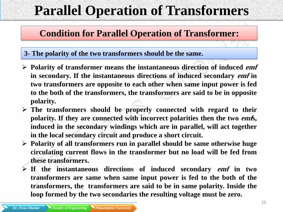
3- The polarity of the two transformers should be the same.
Polarity of transformer means the instantaneous direction of induced emf
in secondary. If the instantaneous directions of induced secondary emf in
two transformers are opposite to each other when same input power is fed
to the both of the transformers, the transformers are said to be in opposite
polarity.
The transformers should be properly connected with regard to their
polarity. If they are connected with incorrect polarities then the two emfs,
induced in the secondary windings which are in parallel, will act together
in the local secondary circuit and produce a short circuit.
Polarity of all transformers run in parallel should be same otherwise huge
circulating current flows in the transformer but no load will be fed from
these transformers.
If the instantaneous directions of induced secondary emf in two
transformers are same when same input power is fed to the both of the
transformers, the transformers are said to be in same polarity. Inside the
loop formed by the two secondaries the resulting voltage must be zero.

26 Dr. Firas Obeidat Faculty of Engineering Philadelphia University
Parallel Operation of Transformers
Condition for Parallel Operation of Transformer:
3- The polarity of the two transformers should be the same.
4- Phase sequences and phase angle shifts must be the same (for three-phase
transformer).
The transformer windings cab be connected in variety of ways which
produce different magnitudes and phase displacement of secondary voltages

27 Dr. Firas Obeidat Faculty of Engineering Philadelphia University
Parallel Operation of Transformers
Overall summary of different connection types of parallel transformers
Transformer
Parallel
Connection Types
Equal
Loading
Unequal
Loading
Overloading
Concerns
Circulating
Currents
Recommended
Connection
Equal impedances—
Equal ratios— Same kVA Yes No No No Yes
Equal impedances—
Equal ratios— Different
kVA
No Yes No No Yes
Unequal impedances—
Equal ratios— Same kVA No Yes Yes No No
Unequal impedances—
Equal ratios— Different
kVA
No Yes Yes No No
Unequal impedances—
Unequal ratios— Same
kVA
Yes No Yes Yes No
Unequal impedances—
Unequal ratios—
Different kVA
No Yes Yes Yes No

28 Dr. Firas Obeidat Faculty of Engineering Philadelphia University
Parallel Operation of Transformers
Case I: Equal Impedances-Equal Ratios-Same kVA
𝐼 = 𝐼𝐴 + 𝐼𝐵
𝐼𝐴 =𝑍𝐵
𝑍𝐴 + 𝑍𝐵𝐼
𝐼𝐵 =𝑍𝐴
𝑍𝐴 + 𝑍𝐵𝐼
𝑉2 = 𝐸 − 𝐼𝐴 𝑍𝐴 = 𝐸 − 𝐼𝐵𝑍𝐵 = 𝐸 − 𝐼𝑍𝐴𝐵
𝐼𝐴 𝑍𝐴 = 𝐼𝐵𝑍𝐵
𝐼𝐴
𝐼𝐵=
𝑍𝐵
𝑍𝐴
Case II: Equal Impedances-Equal Ratios-Different kVA

29 Dr. Firas Obeidat Faculty of Engineering Philadelphia University
Parallel Operation of Transformers
Case I: Equal Impedances-Equal Ratios-Same kVA
𝐼𝐴 =𝐾𝑉𝐴𝐴/%𝑍𝐴
𝐾𝑉𝐴𝐴/%𝑍𝐴 +𝐾𝑉𝐴𝐵/%𝑍𝐵𝐼
𝐼𝐵 =𝐾𝑉𝐴𝐵/%𝑍𝐵
𝐾𝑉𝐴𝐴/%𝑍𝐴 +𝐾𝑉𝐴𝐵/%𝑍𝐵𝐼
𝐾𝑉𝐴𝐴 =𝐾𝑉𝐴𝐴/%𝑍𝐴
𝐾𝑉𝐴𝐴/%𝑍𝐴 +𝐾𝑉𝐴𝐵/%𝑍𝐵𝐾𝑉𝐴𝐿𝑜𝑎𝑑
𝐾𝑉𝐴𝐵 =𝐾𝑉𝐴𝐵/%𝑍𝐵
𝐾𝑉𝐴𝐴/%𝑍𝐴 +𝐾𝑉𝐴𝐵/%𝑍𝐵𝐾𝑉𝐴𝐿𝑜𝑎𝑑
%𝑍𝑇 =𝑍𝑇𝐼𝑇
𝑉𝑇× 100 =
𝑍𝑇
𝑉𝑇2 𝑆𝑇 × 100
Where:
IA = load current from transformer A
IB = load current from transformer B
% ZA = % impedance of transformer A
% ZB = % impedance of transformer B
kVAA = kVA rating of transformer A
kVAB = kVA rating of transformer B
% ZT = % impedance of any transformer
IT = rated current of any transformer
VT = rated voltage of any transformer
ST = KVA rating of any transformer
Case II: Equal Impedances-Equal Ratios-Different kVA

30 Dr. Firas Obeidat Faculty of Engineering Philadelphia University
Parallel Operation of Transformers
Case III: Unequal Impedances-Equal Ratios-Same kVA
Case IV: Unequal Impedances-Equal Ratios-Different kVA
The equations for case III
and Case IV are the same
equations for case I and
case II.

31 Dr. Firas Obeidat Faculty of Engineering Philadelphia University
Parallel Operation of Transformers
Example: Connecting two 2000 kVA, 5.75% impedance transformers in
parallel, each with the same turn ratios to a 4000 kVA load. What is the
loading on the transformers?
𝐾𝑉𝐴𝐴 = 𝐾𝑉𝐴𝐵 =𝐾𝑉𝐴𝐴/%𝑍𝐴
𝐾𝑉𝐴𝐴/%𝑍𝐴 +𝐾𝑉𝐴𝐵/%𝑍𝐵𝐾𝑉𝐴𝐿𝑜𝑎𝑑
𝐾𝑉𝐴𝐴 = 𝐾𝑉𝐴𝐵 =2000/5.75
2000/5.75+2000/5.75× 4000 =
348
348+348× 4000 = 2000 𝐾𝑉𝐴
Example: Connecting 3000 kVA and 1000 kVA transformers in parallel, each
with 5.75% impedance, each with the same turn ratios, connected to a
common 4000 kVA load. What is the loading on each transformer?
𝐾𝑉𝐴𝐴 =𝐾𝑉𝐴𝐴/%𝑍𝐴
𝐾𝑉𝐴𝐴/%𝑍𝐴 +𝐾𝑉𝐴𝐵/%𝑍𝐵𝐾𝑉𝐴𝐿𝑜𝑎𝑑
=3000/5.75
3000/5.75+1000/5.75× 4000 = 3000 𝐾𝑉𝐴

32 Dr. Firas Obeidat Faculty of Engineering Philadelphia University
Parallel Operation of Transformers
𝐾𝑉𝐴𝐵 =𝐾𝑉𝐴𝐵/%𝑍𝐵
𝐾𝑉𝐴𝐴/%𝑍𝐴 +𝐾𝑉𝐴𝐵/%𝑍𝐵𝐾𝑉𝐴𝐿𝑜𝑎𝑑
=1000/5.75
3000/5.75+1000/5.75× 4000 = 1000 𝐾𝑉𝐴
Example: Connecting two 2000 kVA transformers in parallel, one with 5.75%
impedance and the other with 4% impedance, each with the same turn ratios,
connected to a common 3500 kVA load. What is the loading on each
transformer?
𝐾𝑉𝐴𝐴 =𝐾𝑉𝐴𝐴/%𝑍𝐴
𝐾𝑉𝐴𝐴/%𝑍𝐴 +𝐾𝑉𝐴𝐵/%𝑍𝐵𝐾𝑉𝐴𝐿𝑜𝑎𝑑
=2000/5.75
2000/5.75+2000/4× 3500 = 1436 𝐾𝑉𝐴
𝐾𝑉𝐴𝐵 =𝐾𝑉𝐴𝐵/%𝑍𝐵
𝐾𝑉𝐴𝐴/%𝑍𝐴 +𝐾𝑉𝐴𝐵/%𝑍𝐵𝐾𝑉𝐴𝐿𝑜𝑎𝑑
=2000/4
2000/5.75+2000/4× 3500 = 2064 𝐾𝑉𝐴
The 4% impedance
transformer is overloaded
by 3.2%, while the 5.75%
impedance transformer is
loaded by 72%.

33 Dr. Firas Obeidat Faculty of Engineering Philadelphia University
Parallel Operation of Transformers
Example: Connecting two transformers in parallel with one 3000 kVA with
5.75% impedance, and the other a 1000 kVA with 4% impedance, each with
the same turn ratios, connected to a common 3500 kVA load. What is the
loading on each transformer?
𝐾𝑉𝐴𝐴 =𝐾𝑉𝐴𝐴/%𝑍𝐴
𝐾𝑉𝐴𝐴/%𝑍𝐴 +𝐾𝑉𝐴𝐵/%𝑍𝐵𝐾𝑉𝐴𝐿𝑜𝑎𝑑
=3000/5.75
2000/5.75+2000/4× 3500 = 2366 𝐾𝑉𝐴
𝐾𝑉𝐴𝐵 =𝐾𝑉𝐴𝐵/%𝑍𝐵
𝐾𝑉𝐴𝐴/%𝑍𝐴 +𝐾𝑉𝐴𝐵/%𝑍𝐵𝐾𝑉𝐴𝐿𝑜𝑎𝑑
=1000/4
2000/5.75+2000/4× 3500 = 1134 𝐾𝑉𝐴
The 4% impedance transformer is overloaded
by 13.4%, while the 5.75% impedance
transformer is loaded by 78.8%.

34 Dr. Firas Obeidat Faculty of Engineering Philadelphia University
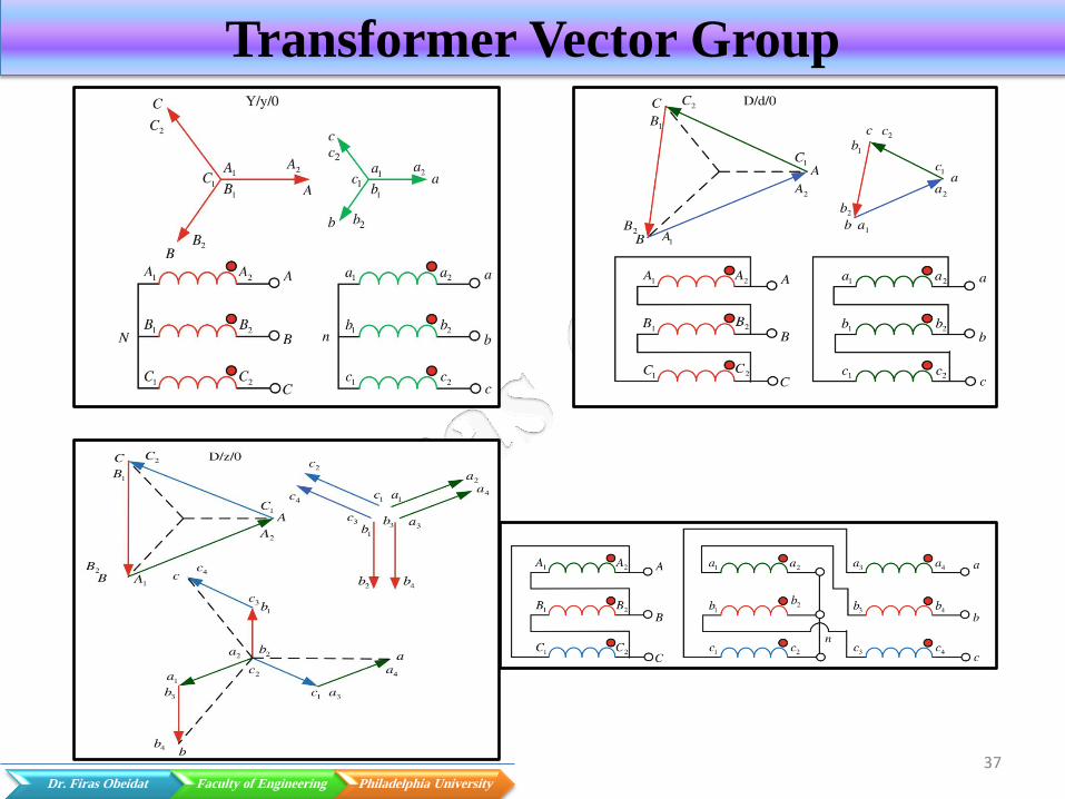
Transformer Vector Group
The primary and secondary windings of a three-phase transformer are
connected either in the same (delta-delta or star-star), or different (delta-
star or star-delta) configuration-pair.
The secondary voltage waveforms of a three-phase transformer are in
phase with the primary waveforms when the primary and secondary
windings are connected in the same configuration. This condition is known
as ‘no phase shift’ condition.
If the primary and secondary windings are connected in different
configuration pair then the secondary voltage waveforms will differ from
the corresponding primary voltage waveforms by 30 electrical degrees.
This condition is called a ‘30° phase shift’ condition.
The windings and their position to each other are usually marked by
vector group. The vector group is used to identify the phase shift between
the primary and secondary windings. In the vector group, the secondary
voltage may have the phase shift of 30° lagging or leading, 0° i.e., no phase
shift or 180° reversal with respect to the primary voltage.

35 Dr. Firas Obeidat Faculty of Engineering Philadelphia University
Transformer Vector Group
The transformer vector group is
labeled by capital and small letters
plus numbers from 1 to 12 in a
typical clock-like diagram.
The capital letter indicates primary
winding and small letter represents
secondary winding.
In the clock diagram, the minute
hand represents the primary line to
neutral line voltage, and its place is
always in the 12. The hour hand
represents the secondary line to
neutral voltage and its position in
the clock changes based on the
phase shift

36 Dr. Firas Obeidat Faculty of Engineering Philadelphia University
Vector Groups Used in the Three Phase Transformer Connection
Group I
0 o’clock, zero phase displacement
Yy0
Dd0
Dz0
Group II
6 o’clock, 180° phase displacement
Yy6
Dd6
Dz6
Group III
1 o’clock, -30° lag phase displacement
Dy1
Yd1
Yz1
Group IV
11 o’clock, 30° lead phase displacement
Dy11
Yd11
Yz11
Transformer Vector Group
37 Dr. Firas Obeidat Faculty of Engineering Philadelphia University
Transformer Vector Group

38 Dr. Firas Obeidat Faculty of Engineering Philadelphia University
Transformer Vector Group

39 Dr. Firas Obeidat Faculty of Engineering Philadelphia University
Transformer Vector Group

40 Dr. Firas Obeidat Faculty of Engineering Philadelphia University
Transformer Vector Group

41