electric power distribution equimpent and · pdf filethe dielectric. the strong attraction of...
TRANSCRIPT

269
6
Capacitor Application
Capacitors provide tremendous benefits to distribution system performance.Most noticeably, capacitors reduce losses, free up capacity, and reduce volt-age drop:
•
Losses; Capacity
—
By canceling the reactive power to motors andother loads with low power factor, capacitors decrease the line cur-rent. Reduced current frees up capacity; the same circuit can servemore load. Reduced current also significantly lowers the
I
2
R
linelosses.
•
Voltage drop
—
Capacitors provide a voltage boost, which cancelspart of the drop caused by system loads. Switched capacitors canregulate voltage on a circuit.
If applied properly and controlled, capacitors can significantly improvethe performance of distribution circuits. But if not properly applied or con-trolled, the reactive power from capacitor banks can create losses and highvoltages. The greatest danger of overvoltages occurs under light load. Goodplanning helps ensure that capacitors are sited properly. More sophisticatedcontrollers (like two-way radios with monitoring) reduce the risk of improp-erly controlling capacitors, compared to simple controllers (like a time clock).
Capacitors work their magic by storing energy. Capacitors are simpledevices: two metal plates sandwiched around an insulating dielectric. Whencharged to a given voltage, opposing charges fill the plates on either side ofthe dielectric. The strong attraction of the charges across the very shortdistance separating them makes a tank of energy. Capacitors oppose changesin voltage; it takes time to fill up the plates with charge, and once charged,it takes time to discharge the voltage.
On ac power systems, capacitors do not store their energy very long —just one-half cycle. Each half cycle, a capacitor charges up and then dis-charges its stored energy back into the system. The net real power transferis zero. Capacitors provide power just when reactive loads need it. Just whena motor with low power factor needs power from the system, the capacitoris there to provide it. Then in the next half cycle, the motor releases its excessenergy, and the capacitor is there to absorb it. Capacitors and reactive loads
9576_C06.fm Page 269 Friday, October 14, 2005 9:21 AM
Copyright © 2006 Taylor & Francis Group, LLC
270
Electric Power Distribution Equipment and Systems
exchange this reactive power back and forth. This benefits the systembecause that reactive power (and extra current) does not have to be trans-mitted from the generators all the way through many transformers and manymiles of lines; the capacitors can provide the reactive power locally. Thisfrees up the lines to carry real power, power that actually does work.
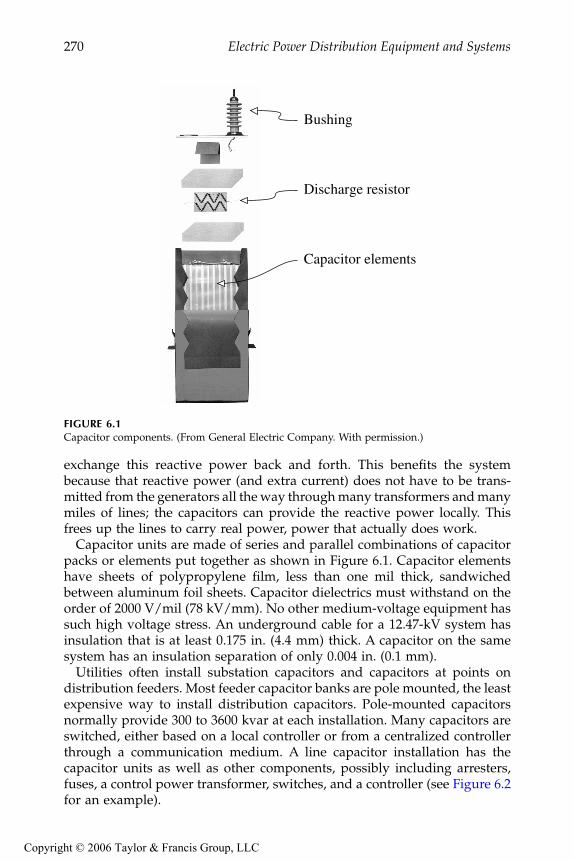
Capacitor units are made of series and parallel combinations of capacitorpacks or elements put together as shown in Figure 6.1. Capacitor elementshave sheets of polypropylene film, less than one mil thick, sandwichedbetween aluminum foil sheets. Capacitor dielectrics must withstand on theorder of 2000 V/mil (78 kV/mm). No other medium-voltage equipment hassuch high voltage stress. An underground cable for a 12.47-kV system hasinsulation that is at least 0.175 in. (4.4 mm) thick. A capacitor on the samesystem has an insulation separation of only 0.004 in. (0.1 mm).
Utilities often install substation capacitors and capacitors at points ondistribution feeders. Most feeder capacitor banks are pole mounted, the leastexpensive way to install distribution capacitors. Pole-mounted capacitorsnormally provide 300 to 3600 kvar at each installation. Many capacitors areswitched, either based on a local controller or from a centralized controllerthrough a communication medium. A line capacitor installation has thecapacitor units as well as other components, possibly including arresters,fuses, a control power transformer, switches, and a controller (see Figure 6.2for an example).
FIGURE 6.1
Capacitor components. (From General Electric Company. With permission.)
Bushing
Discharge resistor
Capacitor elements
9576_C06.fm Page 270 Friday, October 14, 2005 9:21 AM
Copyright © 2006 Taylor & Francis Group, LLC

Capacitor Application
271
While most capacitors are pole mounted, some manufacturers providepadmounted capacitors. As more circuits are put underground, the need forpadmounted capacitors will grow. Padmounted capacitors contain capacitorcans, switches, and fusing in a deadfront package following standard pad-mounted-enclosure integrity requirements (ANSI C57.12.28-1998). Theseunits are much larger than padmounted transformers, so they must be sitedmore carefully to avoid complaints due to aesthetics. The biggest obstaclesare cost and aesthetics. The main complaint is that padmounted capacitorsare large. Customers complain about the intrusion and the aesthetics of sucha large structure (see Figure 6.3).
FIGURE 6.2
Overhead line capacitor installation. (From Cooper Power Systems, Inc. With permission.)
FIGURE 6.3
Example padmounted capacitor. (From Northeast Power Systems, Inc. With permission.)
Vacuumswitch
Control powertransformer
Capacitor unit
9576_C06.fm Page 271 Friday, October 14, 2005 9:21 AM
Copyright © 2006 Taylor & Francis Group, LLC

272
Electric Power Distribution Equipment and Systems
Substation capacitors are normally offered as open-air racks. Normallyelevated to reduce the hazard, individual capacitor units are stacked in rowsto provide large quantities of reactive power. All equipment is exposed. Stackracks require a large substation footprint and are normally engineered forthe given substation. Manufacturers also offer metal-enclosed capacitors,where capacitors, switches, and fuses (normally current-limiting) are allenclosed in a metal housing.
Substation capacitors and feeder capacitors both have their uses. Feedercapacitors are closer to the loads — capacitors closer to loads more effectivelyrelease capacity, improve voltage profiles, and reduce line losses. This isespecially true on long feeders that have considerable line losses and voltagedrop. Table 6.1 highlights some of the differences between feeder and stationcapacitors. Substation capacitors are better when more precise control isneeded. System operators can easily control substation capacitors wired intoa SCADA system to dispatch vars as needed. Modern communication andcontrol technologies applied to feeder capacitors have reduced this advan-tage. Operators can control feeder banks with communications just likestation banks, although some utilities have found the reliability of switchedfeeder banks to be less than desired, and the best times for switching in varsneeded by the system may not correspond to the best time to switch thecapacitor in for the circuit it is located on.
Substation capacitors may also be desirable if a leading power factor isneeded for voltage support. If the power factor is leading, moving this capac-itor out on the feeder increases losses. Substation capacitors cost more thanfeeder capacitors. This may seem surprising, but we must individually engi-neer station capacitors, and the space they take up in a station is often valuablereal estate. Pole-mounted capacitor installations are more standardized.
Utilities normally apply capacitors on three-phase sections. Applicationson single-phase lines are done but less common. Application of three-phasebanks downstream of single-phase protectors is normally not done because
TABLE 6.1
Substation vs. Feeder Capacitors
Advantages Disadvantages
Feeder Capacitors
Reduces line lossesReduces voltage drop along the feederFrees up feeder capacityLower cost
More difficult to control reliablySize and placement important
Substation Capacitors
Better controlBest placement if leading vars are needed for system voltage support
No reduction in line lossesNo reduction in feeder voltage dropHigher cost
9576_C06.fm Page 272 Friday, October 14, 2005 9:21 AM
Copyright © 2006 Taylor & Francis Group, LLC

Capacitor Application
273
of ferroresonance concerns. Most three-phase banks are connectedgrounded-wye on four-wire multigrounded circuits. Some are connected infloating wye. On three-wire circuits, banks are normally connected as afloating wye.
Most utilities also include arresters and fuses on capacitor installations.Arresters protect capacitor banks from lightning-overvoltages. Fuses isolatefailed capacitor units from the system and clear the fault before the capacitorfails violently. In high fault-current areas, utilities may use current-limitingfuses. Switched capacitor units normally have oil or vacuum switches inaddition to a controller. Depending on the type of control, the installationmay include a control power transformer for power and voltage sensing andpossibly a current sensor. Because a capacitor bank has a number of compo-nents, capacitors normally are not applied on poles with other equipment.
Properly applied capacitors return their investment very quickly. Capaci-tors save significant amounts of money in reduced losses. In some cases,reduced loadings and extra capacity can also delay building more distribu-tion infrastructure.
6.1 Capacitor Ratings
Capacitor units rated from 50 to over 500 kvar are available; Table 6.2 showscommon capacitor unit ratings. A capacitor’s rated kvar is the kvar at ratedvoltage. Three-phase capacitor banks are normally referred to by the totalkvar on all three phases. Distribution feeder banks normally have one ortwo or (more rarely) three units per phase. Many common size banks onlyhave one capacitor unit per phase.
IEEE Std. 18 defines standards for capacitors and provides applicationguidelines. Capacitors should not be applied when any of the followinglimits are exceeded (IEEE Std. 18-2002):
• 135% of nameplate kvar• 110% of rated rms voltage, and crest voltage not exceeding 1.2
of rated rms voltage, including harmonics but excluding transients• 135% of nominal rms current based on rated kvar and rated voltage
Capacitor dielectrics must withstand high voltage stresses during normaloperation — on the order of 2000 V/mil. Capacitors are designed to with-stand overvoltages for short periods of time. IEEE Std. 18-1992 allows up to300 power-frequency overvoltages within the time durations in Table 6.3(without transients or harmonic content). New capacitors are tested with atleast a 10-sec overvoltage, either a dc-test voltage of 4.3 times rated rms oran ac voltage of twice the rated rms voltage (IEEE Std. 18-2002).
2
9576_C06.fm Page 273 Friday, October 14, 2005 9:21 AM
Copyright © 2006 Taylor & Francis Group, LLC

274
Electric Power Distribution Equipment and Systems
Capacitors should withstand various peak voltage and current transients;the allowable peak depends on the number of transients expected per year(see Table 6.4).
The capacitance of a unit in microfarads is
TABLE 6.2
Common Capacitor Unit Ratings
Volts, rms(Terminal-to-Terminal) kvar
Numberof Phases BIL, kV
216 5, 7 1/2, 13 1/3, 20, and 25
1 and 3 30
240 2.5, 5, 7 1/2, 10, 15, 20, 25, and 50
1 and 3 30
480, 600 5, 10, 15, 20, 25, 35, 50, 60, and 100
1 and 3 30
2400 50, 100, 150, 200, 300, and 400
1 and 3 75, 95, 125, 150, and 200
2770 50, 100, 150, 200, 300, 400, and 500
1 and 3 75, 95, 125, 150, and 200
4160, 4800 50, 100, 150, 200, 300, 400, 500, 600, 700, and 800
1 and 3 75, 95, 125, 150, and 200
6640, 7200, 7620, 7960, 8320, 9540, 9960, 11,400, 12,470, 13,280, 13,800, 14,400
50, 100, 150, 200, 300, 400, 500, 600, 700, and 800
1 95, 125, 150, and 200
15,125 50, 100, 150, 200, 300, 400, 500, 600, 700, and 800
1 125, 150, and 200
19,920 100, 150, 200, 300, 400, 500, 600, 700, and 800
1 125, 150, and 200
20,800, 21,600, 22,800, 23,800, 24,940
100, 150, 200, 300, 400, 500, 600, 700, and 800
1 150 and 200
Source:
IEEE Std. 18-2002. Copyright 2002 IEEE. All rights reserved.
TABLE 6.3
Maximum Permissible Power-Frequency Voltages
Duration
Maximum Permissible Voltage(multiplying factor to be applied
to rated voltage rms)
6 cycles 2.2015 cycles 2.001 sec 1.7015 sec 1.401 min 1.3030 min 1.25Continuous 1.10
Note:
This is not in IEEE Std. 18-2002 but it will be addressedin IEEE’s updated capacitor application guide.
Source:
ANSI/IEEE Std. 18-1992. Copyright 1993 IEEE. Allrights reserved.
9576_C06.fm Page 274 Friday, October 14, 2005 9:21 AM
Copyright © 2006 Taylor & Francis Group, LLC

Capacitor Application
275
where
V
kV
= capacitor voltage rating, kV
Q
kvar
= unit reactive power rating, kvar
Capacitors are made within a given tolerance. The IEEE standard allowsreactive power to range between 100 and 110% when applied at rated sinu-soidal voltage and frequency (at 25˚C case and internal temperature) (IEEEStd. 18-2002). Older units were allowed to range up to 115% (ANSI/IEEEStd. 18-1992). Therefore, the capacitance also must be between 100 and 110%of the value calculated at rated kvar and voltage. In practice, most units arefrom +0.5 to +4.0%, and a given batch is normally very uniform.
Capacitor losses are typically on the order of 0.07 to 0.15 W/kvar atnominal frequency. Losses include resistive losses in the foil, dielectric losses,and losses in the internal discharge resistor.
Capacitors must have an internal resistor that discharges a capacitor to 50V or less within 5 min when the capacitor is charged to the peak of its ratedvoltage . This resistor is the major component of losses within acapacitor. The resistor must be low enough such that the
RC
time constantcauses it to decay in 300 sec as
where
V
= capacitor voltage rating, V
R
= discharge resistance,
Ω
C
= capacitance, F
TABLE 6.4
Expected Transient Overcurrent and Overvoltage Capability
Probable Numberof Transients
per year
Permissible Peak TransientCurrent (multiplying factor to be
applied to rated rms current)
Permissible Peak Transient Voltage(multiplying factor to be applied to
rated rms voltage)
4 1500 5.040 1150 4.0
400 800 3.44000 400 2.9
Note
: This is not in IEEE Std. 18-2002, but it will be addressed in IEEE’s updated capacitorapplication guide.
Source:
ANSI/IEEE Std. 18-1992. Copyright 1993 IEEE. All rights reserved.
CQ
VuFkvar
kV
=2 65
2
.
( )2Vrms
502
300
Ve RC≤ − /
9576_C06.fm Page 275 Friday, October 14, 2005 9:21 AM
Copyright © 2006 Taylor & Francis Group, LLC

276
Electric Power Distribution Equipment and Systems
So, the discharge resistor must continually dissipate at least the followingpower in watts:
where
Q
kvar
is the capacitor rating (single or three phase). For 7.2-kV capac-itors, the lower bound on losses is 0.047 W/kvar.
Some utilities use a shorting bar across the terminals of capacitors duringshipping and in storage. The standard recommends waiting for 5 min toallow the capacitor to discharge through the internal resistor.
Capacitors have very low losses, so they run very cool. But capacitors arevery sensitive to temperature and are rated for lower temperatures thanother power system equipment such as cables or transformers. Capacitorsdo not have load cycles like transformers; they are always at full load. Also,capacitors are designed to operate at high dielectric stresses, so they haveless margin for degraded insulation. Standards specify an upper limit forapplication of 40 or 46
°
C depending on arrangement (see Table 6.5). Theselimits assume unrestricted ventilation and direct sunlight. At the lower end,IEEE standard 18 specifies that capacitors shall be able to operate continu-ously in a –40˚C ambient.
6.2 Released Capacity
In addition to reducing losses and improving voltage, capacitors releasecapacity. Improving the power factor increases the amount of real-powerload the circuit can supply. Using capacitors to supply reactive powerreduces the amount of current in the line, so a line of a given ampacity can
TABLE 6.5
Maximum Ambient Temperatures for Capacitor Application
Mounting Arrangement
Ambient Air Temperature
(˚C)4-h Average
a
Isolated capacitor 46Single row of capacitors 46Multiple rows and tiers of capacitors 40Metal-enclosed or -housed equipments 40
a
The arithmetic average of the four consecutive highest hourly read-ings during the hottest day expected at that location.
Source:
IEEE Std. 18-2002. Copyright 2002 IEEE. All rights reserved.
PQ
Vwattskvar= − ⎛
⎝⎜
⎞⎠⎟
113 235 36
.ln
.
9576_C06.fm Page 276 Friday, October 14, 2005 9:21 AM
Copyright © 2006 Taylor & Francis Group, LLC

Capacitor Application
277
carry more load. Figure 6.4 shows that capacitors release significant capacity,especially if the original power factor is low. Figure 6.5 shows another wayto view the extra capacity, as a function of the size of capacitor added.
6.3 Voltage Support
Capacitors are constant-impedance devices. At higher voltages, capacitorsdraw more current and produce more reactive power as
I
=
I
rated
V
pu
and
Q
kvar
=
Q
rated
V
pu
2
where
V
pu
is the voltage in per unit of the capacitor’s voltage rating. Capac-itors applied at voltages other than their rating provide vars in proportionto the per-unit voltage squared.
Capacitors provide almost a fixed voltage rise. The reactive currentthrough the system impedance causes a voltage rise in percent of
FIGURE 6.4
Released capacity with improved power factor.
0.60
0.70
0.80
0.90
0.95
1.00 Corrected power factor
0.5 0.6 0.7 0.8 0.9 1.0 0
20
40
60
Original power factor
Ext
ra c
apac
ity, p
erce
nt o
f th
e or
igin
al lo
ad
VQ X
Vrisekvar L
kV l l
= -10 2
,
9576_C06.fm Page 277 Friday, October 14, 2005 9:21 AM
Copyright © 2006 Taylor & Francis Group, LLC

278
Electric Power Distribution Equipment and Systems
where
X
L
= positive-sequence system impedance from the source to the capac-itor,
Ω
V
kV, l-l
= line-to-line system voltage, kV
Q
kvar
= three-phase bank rating, kvar
While this equation is very good for most applications, it is not exactlyright because the capacitive current changes in proportion to voltage. At ahigher operating voltage, a capacitor creates more voltage rise than theequation predicts.
Since the amount of voltage rise is dependent on the impedance upstreamof the bank, to get the voltage boost along the entire circuit, put the capacitorat the end of the circuit. The best location for voltage support depends onwhere the voltage support is needed. Figure 6.6 shows how a capacitorchanges the voltage profile along a circuit. Unlike a regulator, a capacitorchanges the voltage profile upstream of the bank.
Table 6.6 shows the percentage voltage rise from capacitors for commonconductors at different voltages. This table excludes the station transformer
FIGURE 6.5
Extra capacity as a function of capacitor size.
0.6
0.7
0.8
0.9
Original power factor
0 50 1000.6
0.7
0.8
0.9
1.0
0.6
0.7
0.8
0.9
Original power factor:
0 50 100 0
20
40
60
Capacitor kvar in percent of original load kVA
New
pow
er f
acto
rE
xtra
cap
acity
inpe
rcen
t of
the
orig
inal
load
9576_C06.fm Page 278 Friday, October 14, 2005 9:21 AM
Copyright © 2006 Taylor & Francis Group, LLC

Capacitor Application
279
FIGURE 6.6
Voltage profiles after addition of a capacitor bank. (Copyright © 2002. Electric Power ResearchInstitute. 1001691.
Improved Reliability of Switched Capacitor Banks and Capacitor Technology.
Re-printed with permission.)
TABLE 6.6
Percent Voltage Rise for Various Conductors and Voltage Levels
Conductor Size
X
L
ΩΩΩΩ
/mi
Percent Voltage Rise per Mile with 100 kvar per Phase
Line-to-Line System Voltage, kV4.8 12.47 24.9 34.5
4 0.792 1.031 0.153 0.038 0.0202 0.764 0.995 0.147 0.037 0.019
1/0 0.736 0.958 0.142 0.036 0.0194/0 0.694 0.903 0.134 0.034 0.017350 0.656 0.854 0.127 0.032 0.017500 0.635 0.826 0.122 0.031 0.016750 0.608 0.791 0.117 0.029 0.015
Note:
Impedance are for all-aluminum conductors with GMD=4.8 ft.
Voltage rise from the capacitor
Voltage profile with the capacitor
Voltage profile without the capacitor
100
102
104
96
98
100
With no load
With load
Voltage profile without the capacitor
Feed
ervo
ltage
,per
cent
9576_C06.fm Page 279 Friday, October 14, 2005 9:21 AM
Copyright © 2006 Taylor & Francis Group, LLC

280
Electric Power Distribution Equipment and Systems
impedance but still provides a useful approximation. Inductance does notchange much with conductor size; the voltage change stays the same overa wide range of conductor sizes. For 15-kV class systems, capacitors increasethe voltage by about 0.12% per mi per 100 kvar per phase.
On switched capacitor banks, the voltage change constrains the size ofbanks at some locations. Normally, utilities limit the voltage change to 3 to4%. On a 12.47-kV circuit, a three-phase 1200-kvar bank boosts the voltage4% at about 8 mi from the substation. To keep within a 4% limit, 1200-kvarbanks must only be used within the first 8 mi of the station.
6.4 Reducing Line Losses
One of the main benefits of applying capacitors is that they can reducedistribution line losses. Losses come from current through the resistance ofconductors. Some of that current transmits real power, but some flows tosupply reactive power. Reactive power provides magnetizing for motors andother inductive loads. Reactive power does not spin kWh meters and per-forms no useful work, but it must be supplied. Using capacitors to supplyreactive power reduces the amount of current in the line. Since line lossesare a function of the current squared,
I
2
R
, reducing reactive power flow onlines significantly reduces losses.
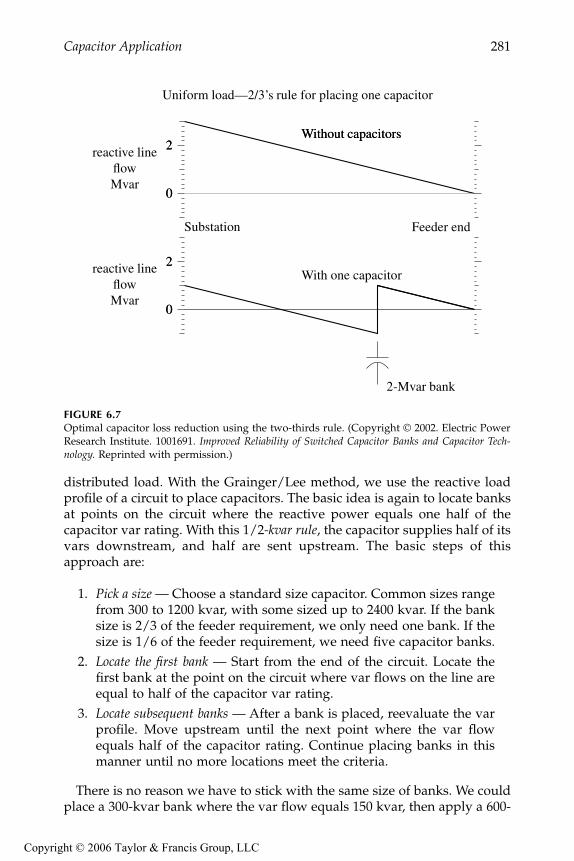
Engineers widely use the “2/3 rule” for sizing and placing capacitors tooptimally reduce losses. Neagle and Samson (1956) developed a capacitorplacement approach for uniformly distributed lines and showed that theoptimal capacitor location is the point on the circuit where the reactive powerflow equals half of the capacitor var rating. From this, they developed the2/3 rule for selecting and placing capacitors. For a uniformly distributedload, the optimal size capacitor is 2/3 of the var requirements of the circuit.The optimal placement of this capacitor is 2/3 of the distance from thesubstation to the end of the line. For this optimal placement for a uniformlydistributed load, the substation source provides vars for the first 1/3 of thecircuit, and the capacitor provides vars for the last 2/3 of the circuit (seeFigure 6.7).
A generalization of the 2/3 rule for applying
n
capacitors to a circuit is tosize each one to 2/(2
n
+1) of the circuit var requirements. Apply them equallyspaced, starting at a distance of 2/(2
n
+1) of the total line length from thesubstation and adding the rest of the units at intervals of 2/(2
n
+1) of thetotal line length. The total vars supplied by the capacitors is 2
n
/(2
n
+1) ofthe circuit’s var requirements. So to apply three capacitors, size each to 2/7of the total vars needed, and locate them at per unit distances of 2/7, 4/7,and 6/7 of the line length from the substation.
Grainger and Lee (1981) provide an optimal yet simple method for placingfixed capacitors on a circuit with any load profile, not just a uniformly
9576_C06.fm Page 280 Friday, October 14, 2005 9:21 AM
Copyright © 2006 Taylor & Francis Group, LLC
Capacitor Application
281
distributed load. With the Grainger/Lee method, we use the reactive loadprofile of a circuit to place capacitors. The basic idea is again to locate banksat points on the circuit where the reactive power equals one half of thecapacitor var rating. With this 1/2
-kvar rule
, the capacitor supplies half of itsvars downstream, and half are sent upstream. The basic steps of thisapproach are:
1.
Pick a size —
Choose a standard size capacitor. Common sizes rangefrom 300 to 1200 kvar, with some sized up to 2400 kvar. If the banksize is 2/3 of the feeder requirement, we only need one bank. If thesize is 1/6 of the feeder requirement, we need five capacitor banks.
2.
Locate the first bank
— Start from the end of the circuit. Locate thefirst bank at the point on the circuit where var flows on the line areequal to half of the capacitor var rating.
3.
Locate subsequent banks
— After a bank is placed, reevaluate the varprofile. Move upstream until the next point where the var flowequals half of the capacitor rating. Continue placing banks in thismanner until no more locations meet the criteria.
There is no reason we have to stick with the same size of banks. We couldplace a 300-kvar bank where the var flow equals 150 kvar, then apply a 600-
FIGURE 6.7
Optimal capacitor loss reduction using the two-thirds rule. (Copyright © 2002. Electric PowerResearch Institute. 1001691.
Improved Reliability of Switched Capacitor Banks and Capacitor Tech-nology.
Reprinted with permission.)
0
2
0
2reactive lineflowMvar
Uniform load—2/3’s rule for placing one capacitor
Substation Feeder end
0
2
0
2reactive lineflowMvar
Without capacitors
2-Mvar bank
Without capacitors
With one capacitor
9576_C06.fm Page 281 Friday, October 14, 2005 9:21 AM
Copyright © 2006 Taylor & Francis Group, LLC
282
Electric Power Distribution Equipment and Systems
kvar bank where the var flow equals 300 kvar, and finally apply a 450-kvarbank where the var flow equals 225 kvar. Normally, it is more efficient touse standardized bank sizes, but different size banks at different portions ofthe feeder might help with voltage profiles.
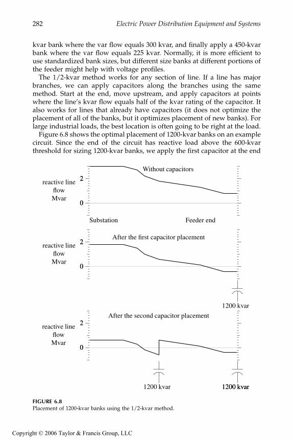
The 1/2-kvar method works for any section of line. If a line has majorbranches, we can apply capacitors along the branches using the samemethod. Start at the end, move upstream, and apply capacitors at pointswhere the line’s kvar flow equals half of the kvar rating of the capacitor. Italso works for lines that already have capacitors (it does not optimize theplacement of all of the banks, but it optimizes placement of new banks). Forlarge industrial loads, the best location is often going to be right at the load.
Figure 6.8 shows the optimal placement of 1200-kvar banks on an examplecircuit. Since the end of the circuit has reactive load above the 600-kvarthreshold for sizing 1200-kvar banks, we apply the first capacitor at the end
FIGURE 6.8
Placement of 1200-kvar banks using the 1/2-kvar method.
0
2
0
2reactive lineflowMvar
Substation Feeder end
0
2
0
2reactive lineflowMvar
Without capacitors
1200 kvar
After the first capacitor placement
0
2
0
2
1200 kvar
After the second capacitor placement
1200 kvar1200 kvar
reactive lineflowMvar
9576_C06.fm Page 282 Friday, October 14, 2005 9:21 AM
Copyright © 2006 Taylor & Francis Group, LLC

Capacitor Application
283
of the circuit. (The circuit at the end of the line could be one large customeror branches off the main line.) The second bank goes near the middle. Thecircuit has an express feeder near the start. Another 1200-kvar bank couldgo in just after the express feeder, but that does not buy us anything. Thetwo capacitors total 2400 kvar, and the feeder load is 3000 kvar. We reallyneed another 600-kvar capacitor to zero out the var flow before it gets to theexpress feeder.
Fortunately, capacitor placement and sizing does not have to be exact.Quite good loss reduction occurs even if sizing and placement are not exactlyoptimum. Figure 6.9 shows the loss reduction for one fixed capacitor on acircuit with a uniform load. The 2/3 rule specifies that the optimum distanceis 2/3 of the distance from the substation and 2/3 of the circuit’s var require-ment. As long as the size and location are somewhat close (within 10%), thenot-quite-optimal capacitor placement provides almost as much loss reduc-tion as the optimal placement.
Consider the voltage impacts of capacitors. Under light load, check thatthe capacitors have not raised the voltages above allowable standards. Ifvoltage limits are exceeded, reduce the size of the capacitor banks or thenumber of capacitor banks until voltage limits are not exceeded. If additionalloss reduction is desired, consider switched banks as discussed below.
6.4.1 Energy Losses
Use the average reactive loading profile to optimally size and place capaci-tors for energy losses. If we use the peak-load case, the 1/2-kvar method
FIGURE 6.9
Sensitivity to losses of sizing and placing one capacitor on a circuit with a uniform load. (Thecircles mark the optimum location for each of the sizes shown.)
506775
85
Capacitor size as a percentageof the feeder’s reactive load
0 20 40 60 80 100 0
20
40
60
80
Capacitor location, percent of the total line length
Los
s re
duct
ion
in p
erce
ntof
the
tota
l los
ses
due
to r
eact
ive
pow
er
9576_C06.fm Page 283 Friday, October 14, 2005 9:21 AM
Copyright © 2006 Taylor & Francis Group, LLC

284
Electric Power Distribution Equipment and Systems
optimizes losses during the peak load. If we have a load-flow case with theaverage reactive load, the 1/2-kvar method or the 2/3 rule optimizes energylosses. This leads to more separation between banks and less kvars appliedthan if we optimize for peak losses.
If an average system case is not available, then we can estimate it by scalingthe peak load case by the reactive load factor,
RLF
:
The reactive load factor is similar to the traditional load factor except thatit only considers the reactive portion of the load. If we have no informationon the reactive load factor, use the total load factor. Normally, the reactiveload factor is higher than the total load factor. Figure 6.10 shows an exampleof power profiles; the real power (kW) fluctuates significantly more than thereactive power (kvar).
6.5 Switched Banks
Switched banks provide benefits under the following situations:
•
More loss reduction
— As the reactive loading on the circuit changes,we reduce losses by switching banks on and off to track thesechanges.
•
Voltage limits
— If optimally applied banks under the average load-ing scenario cause excessive voltage under light load, then useswitched banks.
In addition, automated capacitors — those with communications — havethe flexibility to also use distribution vars for transmission support.
Fixed banks are relatively easy to site and size optimally. Switched banksare more difficult. Optimally sizing capacitors, placing them, and decidingwhen to switch them are difficult tasks. Several software packages are avail-able that can optimize this solution. This is an intensely studied area, andtechnical literature documents several approaches (among these Carlisle andEl-Keib, 2000; Grainger and Civanlar, 1985; Shyh, 2000).
To place switched capacitors using the 1/2-kvar method, again place thebanks at the location where the line kvar equals half the bank rating. Butinstead of using the average reactive load profile (the rule for fixed banks),use the average reactive flow during the time the capacitor is on. With time-switched banks and information on load profiles (or typical load profiles),
RLF = Average kvar Demand
Peak kvar Demand
9576_C06.fm Page 284 Friday, October 14, 2005 9:21 AM
Copyright © 2006 Taylor & Francis Group, LLC

Capacitor Application
285
we can pick the on time and the off time and determine the proper sizingbased on the average reactive flow between the on and off times. Or, we canplace a bank and pick the on and off times such that the average reactiveline flow while the bank is switched on equals half of the bank rating. Inthese cases, we have specified the size and either the placement or switchingtime. To more generally optimize — including sizing, placement, number ofbanks, and switching time — we must use a computer, which iterates to finda solution [see Lee and Grainger (1981) for one example].
Combinations of fixed and switched banks are more difficult. The fol-lowing approach is not optimal but gives reasonable results. Apply fixedbanks to the circuit with the 1/2-kvar rule based on the light-load case.Check voltages. If there are undervoltages, increase the size of capacitors,use more capacitor banks, or add regulators. Now, look for locations suit-able for switched banks. Again, use the average reactive line flows for thetime when the capacitor is on (with the already-placed fixed capacitors inthe circuit model). When applying switched capacitors, check the light-load case for possible overvoltages, and check the peak-load case for under-voltages.
FIGURE 6.10Example of real and reactive power profiles on a residential feeder on a peak summer day with95% air conditioning. (Data from East Central Oklahoma Electric Cooperative, Inc. [RUS 1724D-112, 2001].)
kVA
kW
kvar
00:00 06:00 12:00 18:00 24:00
40
60
80
100
00:00 06:00 12:00 18:00 24:00 70
80
90
Perc
ent o
f th
e da
ily k
VA
pea
kT
empe
ratu
re, d
egF
9576_C06.fm Page 285 Friday, October 14, 2005 9:21 AM
Copyright © 2006 Taylor & Francis Group, LLC

286 Electric Power Distribution Equipment and Systems
6.6 Local Controls
Several options for controls are available for capacitor banks:
• Time clock — The simplest scheme: the controller switches capacitorson and off based on the time of day. The on time and the off timeare programmable. Modern controllers allow settings for weekendsand holidays. This control is the cheapest but also the most suscep-tible to energizing the capacitor at the wrong time (due to loadsbeing different from those expected, to holidays or other unexpectedlight periods, and especially to mistakenly set or inaccurate clocks).Time clock control is predictable; capacitors switch on and off atknown times and the controller limits the number of switching oper-ations (one energization and one deenergization per day).
• Temperature — Another simple control; the controller switches thecapacitor bank on or off depending on temperature. Normally thesemight be set to turn the capacitors on in the range of 85 and 90°Fand turn them off at temperatures somewhere between 75 and 80°F.
• Voltage — The capacitor switches on and off, based on voltage. Theuser provides the threshold minimum and maximum voltages aswell as time delays and bandwidths to prevent excessive operations.Voltage control is most appropriate when the primary role of acapacitor is voltage support and regulation.
• Vars — The capacitor uses var measurements to determine switch-ing. This is the most accurate method of ensuring that the capacitoris on at the appropriate times for maximum reduction of losses.
• Power factor — Similar to var control, the controller switches capac-itors on and off based on the measured power factor. This is rarelyused by utilities.
• Current — The capacitor switches on and off based on the line current(as measured downstream of the capacitor). While not as effectiveas var control, current control does engage the capacitor duringheavy loads, which usually corresponds to the highest needs for vars.
Many controllers offer many or all of these possibilities. Many are usablein combination; turn capacitors on for low voltage or for high temperature.
Var, power factor, voltage, or current controllers require voltage or currentsensing or both. To minimize cost and complexity, controllers often switchall three phases using sensors on just one phase. A control power transformeris often also used to sense voltage. While unusual, Alabama Power switcheseach phase independently depending on the var requirements of each phase(Clark, 2001); this optimizes loss reduction and helps reduce unbalance.Because capacitor structures are rather busy, some utilities like to use voltage
9576_C06.fm Page 286 Friday, October 14, 2005 9:21 AM
Copyright © 2006 Taylor & Francis Group, LLC

Capacitor Application 287
and/or current-sensing insulators. Meter-grade accuracy is not needed forcontrolling capacitors.
To coordinate more than one capacitor with switched var controls, set themost-distant unit to have the shortest time delay. Increase the time delay onsuccessive units progressing back to the substation. This leaves the unitclosest to the substation with the longest time delay. The most distant unitswitches first. Upstream units see the change and do not need to respond.This strategy is the opposite of that used for coordinating multiple linevoltage regulators.
For var-controlled banks, locate the current sensor on the source (substa-tion) side of the bank. Then, the controller can detect the reactive powerchange when the capacitor switches. To properly calculate vars, the wiringfor the CT and PT must provide correct polarities to the controller.
One manufacturer provides the following rules of thumb for setting varcontrol trip and close settings (Fisher Pierce, 2000):
• Close setpoint: 2/3 × capacitor bank size (in kvar), lagging.• Trip setpoint: Close set point – 1.25 × bank size, will be leading. (This
assumes that the CT is on the source side of the bank.)
For a 600-kvar bank application, this yields
Close setpoint: 2/3 × 600 = +400 kvar (lagging)Trip setpoint: 400 – 1.25 × 600 = –350 kvar (leading)
For this example, the unit trips when the load kvar drops below +250 kvar(lagging). This effectively gives a bandwidth wide enough (+400 to +250kvar) to prevent excessive switching operations in most cases.
Voltage-controlled capacitor banks have bandwidths. Normally, we wantthe bandwidth to be at least 1.5 times the expected voltage change due tothe capacitor bank. Ensure that the bandwidth is at least 3 or 4 V (on a 120-V scale). Set the trip setting below the normal light-load voltage (or the bankwill never switch off).
If a switched capacitor is located on a circuit that can be operated fromeither direction, make sure the controller mode can handle operation withpower flow in either direction. Time-of-day, temperature, and voltage controlare not affected by reverse power flow; var, current, and power factor controlare affected. Some controllers can sense reverse power and shift controlmodes. One model provides several options if it detects reverse power:switch to voltage mode, calculate var control while accounting for the effectof the capacitor bank, inhibit switching, trip and lock out the bank, or closeand hold the bank in. If a circuit has distributed generation, we do not wantto shift modes based on reverse power flow; the controller should shiftmodes only for a change in direction to the system source.
9576_C06.fm Page 287 Friday, October 14, 2005 9:21 AM
Copyright © 2006 Taylor & Francis Group, LLC

288 Electric Power Distribution Equipment and Systems
Capacitor controllers normally have counters to record the number ofoperations. The counters help identify when to perform maintenance andcan identify control-setting problems. For installations that are excessivelyswitching, modify control settings, time delays, or bandwidths to reduceswitching. Some controllers can limit the number of switch operations withina given time period to reduce wear on capacitor switches.
Voltage control provides extra safety to prevent capacitors from causingovervoltages. Some controllers offer types of voltage override control; theprimary control may be current, vars, temperature, or time of day, but thecontroller trips the bank if it detects excessive voltage. A controller may alsorestrain from switching in if the extra voltage rise from the bank would pushthe voltage above a given limit.
6.7 Automated Controls
Riding the tide of lower-cost wireless communication technologies, manyutilities have automated capacitor banks. Many of the cost reductions andfeature improvements in communication systems have resulted from theproliferation of cellular phones, pagers, and other wireless technologies usedby consumers and by industry. Controlling capacitors requires little band-width, so high-speed connections are unnecessary. This technology changesquickly. The most common communications systems for distribution linecapacitors are 900-MHz radio systems, pager systems, cellular phone sys-tems, cellular telemetric systems, and VHF radio. Some of the commonfeatures of each are
• 900-MHz radio — Very common. Several spread-spectrum dataradios are available that cover 902–928 MHz applications. A privatenetwork requires an infrastructure of transmission towers.
• Pager systems — Mostly one-way, but some two-way, communica-tions. Pagers offer inexpensive communications options, especiallyfor infrequent usage. One-way communication coverage is wide-spread; two-way coverage is more limited (clustered around majorcities). Many of the commercial paging networks are suitable forcapacitor switching applications.
• Cellular phone systems — These use one of the cellular networks toprovide two-way communications. Many vendors offer cellularmodems for use with several cellular networks. Coverage is typicallyvery good.
• Cellular telemetric systems — These use the unused data componentof cellular signals that are licensed on existing cellular networks.They allow only very small messages to be sent — enough, though,
9576_C06.fm Page 288 Friday, October 14, 2005 9:21 AM
Copyright © 2006 Taylor & Francis Group, LLC

Capacitor Application 289
to perform basic capacitor automation needs. Coverage is typicallyvery good, the same as regular cellular coverage.
• VHF radio — Inexpensive one-way communications are possiblewith VHF radio communication. VHF radio bands are available fortelemetry uses such as this. Another option is a simulcast FM signalthat uses extra bandwidth available in the commercial FM band.
Standard communication protocols help ease the building of automatedinfrastructures. Equipment and databases are more easily interfaced with stan-dard protocols. Common communication protocols used today for SCADAapplications and utility control systems include DNP3, IEC 870, and Modbus.
DNP 3.0 (Distributed Network Protocol) is the most widely used standardprotocol for capacitor controllers (DNP Users Group, 2000). It originated inthe electric industry in America with Harris Distributed Automation Prod-ucts and was based on drafts of the IEC870-5 SCADA protocol standards(now known as IEC 60870-5). DNP supports master–slave and peer-to-peercommunication architectures. The protocol allows extensions while still pro-viding interoperability. Data objects can be added to the protocol withoutaffecting the way that devices interoperate. DNP3 was designed for trans-mitting data acquisition information and control commands from one com-puter to another. (It is not a general purpose protocol for hypertext,multimedia, or huge files.)
One-way or two-way — we can remotely control capacitors either way.Two-way communication has several advantages:
• Feedback — A local controller can confirm that a capacitor switchedon or off successfully. Utilities can use the feedback from two-waycommunications to dispatch crews to fix capacitor banks with blownfuses, stuck switches, misoperating controllers, or other problems.
• Voltage/var information — Local information on line var flows andline voltages allows the control to more optimally switch capacitorbanks to reduce losses and keep voltages within limits.
• Load flows — Voltage, current, and power flow information frompole-mounted capacitor banks can be used to update and verifyload-flow models of a system. The information can also help whentracking down customer voltage, stray voltage, or other power qual-ity problems. Loading data helps utilities monitor load growth andplan for future upgrades. One utility even uses capacitor controllersto capture fault location information helping crews to locate faults.
When a controller only has one-way communications, a local voltage over-ride control feature is often used. The controller blocks energizing a capacitorbank if doing so would push the voltage over limits set by the user.
Several schemes and combinations of schemes are used to control capac-itors remotely:
9576_C06.fm Page 289 Friday, October 14, 2005 9:21 AM
Copyright © 2006 Taylor & Francis Group, LLC

290 Electric Power Distribution Equipment and Systems
• Operator dispatch — Most schemes allow operators to dispatch dis-tribution capacitors. This feature is one of the key reasons utilitiesautomate capacitor banks. Operators can dispatch distributioncapacitors just like large station banks. If vars are needed for trans-mission support, large numbers of distribution banks can beswitched on. This control scheme is usually used in conjunction withother controls.
• Time scheduling — Capacitors can be remotely switched, based onthe time of day and possibly the season or temperature. While thismay seem like an expensive time control, it still allows operators tooverride the schedule and dispatch vars as needed.
• Substation var measurement — A common way to control feedercapacitors is to dispatch based on var/power factor measurementsin the substation. If a feeder has three capacitor banks, they areswitched on or off in some specified order based on the power factoron the feeder measured in the substation.
• Others — More advanced (and complicated) algorithms can dispatchcapacitors based on a combination of local var measurements andvoltage measurements along with substation var measurements.
6.8 Reliability
Several problems contribute to the overall reliability or unreliability of capac-itor banks. In a detailed analysis of Kansas City Power & Light’s automatedcapacitor banks, Goeckeler (1999) reported that blown fuses are KCP&L’sbiggest problem, but several other problems exist (Table 6.7). Their automa-
TABLE 6.7
Maintenance Needs Identified by Kansas City Power & Light’s Capacitor Automation System Based on Two Years of Data
ProblemAnnual Percent
Failures
Primary fuse to capacitor blown (nuisance fuse operation) 9.1Failed oil switches 8.1Hardware accidentally set to “Local” or “Manual” 4.2Defective capacitor unit 3.5Miscellaneous 2.4Control power transformer 1.5TOTAL 28.8
Source: Goeckeler, C., “Progressive Capacitor Automation Yields Economic andPractical Benefits at KCPL,” Utility Automation, October 1999.
9576_C06.fm Page 290 Friday, October 14, 2005 9:21 AM
Copyright © 2006 Taylor & Francis Group, LLC

Capacitor Application 291
tion with two-way communications allowed them to readily identify bankfailures. The failure rates in Table 6.7 are high, much higher than mostdistribution equipment. Capacitor banks are complicated; they have a lot ofequipment to fail; yet, failure rates should be significantly better than this.
An EPRI survey on capacitor reliability found wide differences in utilities’experience with capacitors (EPRI 1001691, 2002). Roughly one-third of sur-vey responses found feeder capacitors “very good,” another one-thirdfound them “typical of line equipment,” and the final third found them“problematic.” The survey along with follow-up contacts highlighted sev-eral issues:
• Misoperation of capacitor fuses — Many utilities have operations offuses where the capacitor bank is unharmed. This can unbalancecircuit voltages and reduce the number of capacitors available forvar support. Review fusing practices to reduce this problem.
• Controllers — Controllers were found “problematic” by a significantnumber of utilities. Some utilities had problems with switches andwith the controllers themselves.
• Lightning and faults — In high-lightning areas, controllers can failfrom lightning. Controllers are quite exposed to lightning andpower-supply overvoltages during faults. Review surge protectionpractices and powering and grounding of controllers.
• Human element — Many controllers are set up incorrectly. Somecontrollers are hard to program. And, field crews often do not havethe skills or proper attitudes toward capacitors and their controls.At some utilities, crews often manually switch off nearby capacitors(and often forget to turn them back on after finishing their work).To reduce these problems, properly train crews and drive home theneed to have capacitors available when needed.
6.9 Failure Modes and Case Ruptures
Capacitors can fail in two modes:
• Low current, progressive failure — The dielectric fails in one of theelements within the capacitor (see Figure 6.11). With one elementshorted, the remaining elements in the series string have increasedvoltage and higher current (because the total capacitive impedanceis lower). With more stress, another element may short out. Failurescan cascade until the whole string shorts out. In this scenario, thecurrent builds up slowly as elements successively fail.
9576_C06.fm Page 291 Friday, October 14, 2005 9:21 AM
Copyright © 2006 Taylor & Francis Group, LLC

292 Electric Power Distribution Equipment and Systems
• High current — A low-impedance failure develops across the capac-itor terminals or from a phase terminal to ground. A broken connec-tor could cause such a fault.
Most failures are progressive. Sudden jumps to high current are rare. Todetect progressive failures quickly, fusing must be very sensitive. Film-foilcapacitors have few case ruptures — much less than older paper units. AnEPRI survey of utilities (EPRI 1001691, 2002) found that film-foil capacitorruptures were rare to nonexistent. This contrasts sharply with paper capac-itors, where Newcomb (1980) reported that film/paper capacitors rupturedin 25% of failures.
Paper and paper-film capacitors have an insulating layer of paper betweensheets of foil. When a breakdown in a pack occurs, the arc burns the paperand generates gas. In progressive failures, even though the current is onlysomewhat higher than normal load current, the sustained arcing can createenough gas to rupture the enclosure. Before 1975, capacitors predominantlyused polychlorinated biphenyls (PCB) as the insulating liquid. Environmen-tal regulations on PCB greatly increased the costs of cleanup if these unitsruptured (U.S. Environmental Protection Agency 40 CFR Part 761 Polychlo-rinated Biphenyls (PCBs) Manufacturing, Processing, Distribution in Com-merce, and Use Prohibitions). The environmental issues and safety concernsled utilities to tighten up capacitor fusing.
In modern film-foil capacitors, sheets of polypropylene film dielectric sep-arate layers of aluminum foil. When the dielectric breaks down, the heatfrom the arc melts the film; the film draws back; and the aluminum sheetsweld together. With a solid weld, a single element can fail and not createany gas (the current is still relatively low). In film-foil capacitors, the pro-gressive failure mode is much less likely to rupture the case. When all of the
FIGURE 6.11Capacitor unit with a failed element.
Individual element
Failed element
Series section
9576_C06.fm Page 292 Friday, October 14, 2005 9:21 AM
Copyright © 2006 Taylor & Francis Group, LLC

Capacitor Application 293
packs in series fail, high current flows through the capacitor. This can gen-erate enough heat and gas to rupture the capacitor if it is not cleared quickly.
Figure 6.12 shows capacitor-rupture curves from several sources. Mostcase-rupture curves are based on tests of prefailed capacitors. The capacitorsare failed by applying excessive voltage until the whole capacitor is brokendown. The failed capacitor is then subjected to a high-current short-circuit
FIGURE 6.12Capacitor rupture curves. (Data from [ANSI/IEEE Std. 18-1992; Cooper Power Systems, 1990;General Electric, 2001].)
1
2
3
4
1: Cooper2: GE, 300 kvar and above3: NEMA film/foil4: NEMA paper-film
10+2 10+3 10+40.01
0.1
1.0
10.0
100.0
Current, amperes
Tim
e, s
econ
ds
9576_C06.fm Page 293 Friday, October 14, 2005 9:21 AM
Copyright © 2006 Taylor & Francis Group, LLC

294 Electric Power Distribution Equipment and Systems
source of known amperage for a given time. Several such samples are testedto develop a case-rupture curve.
The case-rupture curves do not represent all failure modes. Such curvesdo not show the performance during the most common failures: low-currentand progressive element failures (before all elements are punctured).Although, thankfully, rare, high-current faults more severe than those testedfor the rupture curves are possible. An arc through the insulating dielectricfluid can generate considerable pressure. Pratt et al. (1977) performed testson film/foil capacitor units with arc lengths up to 3 in. (7.6 cm) in length.They chose 3 in. as the maximum realistic arc length in a capacitor as thegap spacing between internal series section terminals. Under these condi-tions, they damaged or ruptured several units for currents and times wellbelow the capacitor rupture curves in Figure 6.12.
Also consider other equipment at a capacitor bank installation. Capacitorswitches, especially oil switches, are vulnerable to violent failure. This typeof failure has not received nearly the attention that capacitor ruptures ordistribution transformer failures have. Potential transformers, currenttransformers, controller power-supply transformers, and arresters: thesetoo can fail violently. Any failure in which an arc develops inside a smallenclosure can rupture or explode. In areas with high fault current, considerapplying current-limiting fuses. These will help protect against violentfailures of capacitor units, switches, and other accessories in areas withhigh fault current.
When one element fails and shorts out, the other series sections have highervoltage, and they draw more current. Capacitor packs are designed with apolypropylene film layer less than one mil thick (0.001 in. or 0.025 mm),which is designed to hold a voltage of 2000 V. Table 6.8 shows the numberof series sections for several capacitors as reported by Thomas (1990). Morerecent designs could have even fewer groups. One manufacturer uses threeseries sections for 7.2 to 7.96 kV units and six series sections for 12.47 to 14.4kV units. As series sections fail, the remaining elements must hold increasingvoltage, and the capacitor draws more current in the same proportion. Figure
TABLE 6.8
Number of Series Sections in Different Voltage Ratings
Unit Voltage, VManufacturer
A B C
2,400 2 2 27,200 4 4 47,620 5 5 4
13,280 8 8 713,800 8 8 —14,400 8 8 8
Source: Thomas, E. S., “Determination of Neutral Trip Settingsfor Distribution Capacitor Banks,” IEEE Rural Electric PowerConference, 1990. With permission. ©1990 IEEE.
9576_C06.fm Page 294 Friday, October 14, 2005 9:21 AM
Copyright © 2006 Taylor & Francis Group, LLC

Capacitor Application 295
6.13 shows the effect on the per-unit current drawn by a failing unit and theper-unit voltage on the remaining series sections.
If a capacitor bank has multiple units on one phase and all units areprotected by one fuse (group fusing), the total bank current should be con-sidered. Consider a bank with two capacitor units. If one unit loses half ofits series sections, that unit will draw twice its nominal current. The group— the two units together — will draw 1.5 times the nominal bank load. (Thisis the current that the fuse sees.)
6.10 Fusing and Protection
The main purpose of the fuse on a capacitor bank is to clear a fault if acapacitor unit or any of the accessories fail. The fuse must clear the faultquickly to prevent any of the equipment from failing violently. Ruptures ofcapacitors have historically been problematic, so fusing is normally tight.Fuses must be sized to withstand normal currents, including harmonics.
A significant number of utilities have problems with nuisance fuse oper-ations on capacitor banks. A fuse is blown, but the capacitors themselves arestill functional. These blown fuses may stay on the system for quite sometime before they are noticed (see Figure 6.14). Capacitors with blown fusesincrease voltage unbalance, can increase stray voltages, and increase losses.Even if the capacitor controller identifies blown fuses, replacement addsextra maintenance that crews must do.
FIGURE 6.13Per-unit current drawn by a failing bank depending on the portion of the bank that is failed(assuming an infinite bus). This is also the per-unit voltage applied on the series sections stillremaining.
0 20 40 60 1
2
3
4
Percent of the series packs shorted out
Per-
unit
curr
ent a
nd v
olta
ge
9576_C06.fm Page 295 Friday, October 14, 2005 9:21 AM
Copyright © 2006 Taylor & Francis Group, LLC

296 Electric Power Distribution Equipment and Systems
IEEE guides suggest selecting a fuse capable of handling 1.25 to 1.35 timesthe nominal capacitor current (IEEE Std. C37.48-1997); a 1.35 factor is mostcommon. Three factors can contribute to higher than expected current:
• Overvoltage — Capacitive current increases linearly with voltage, andthe reactive vars increase as the square of the voltage. When esti-mating maximum currents, an upper voltage limit of 110% is nor-mally assumed.
• Harmonics — Capacitors can act as a sink for harmonics. This canincrease the peak and the rms of the current through the capacitor.Additionally, grounded three-phase banks absorb zero-sequenceharmonics from the system.
• Capacitor tolerance — Capacitors were allowed to have a tolerance to+15% above their rating (which would increase the current by 15%).
Most fusing practices are based on fusing as tightly as possible to preventcase rupture. So, the overload capability of fuse links is included in fusesizing. This effectively allows a tighter fusing ratio. K and T tin links can beoverloaded to 150%, so for these links with a 1.35 safety factor, the smallestsize fuse that can be used is
FIGURE 6.14Capacitor bank with a blown fuse. (Copyright © 2002. Electric Power Research Institute. 1001691.Improved Reliability of Switched Capacitor Banks and Capacitor Technology. Reprinted with permission.)
9576_C06.fm Page 296 Friday, October 14, 2005 9:21 AM
Copyright © 2006 Taylor & Francis Group, LLC

Capacitor Application 297
whereImin = minimum fuse rating, A
I1 = capacitor bank current, A
Table 6.9 shows one manufacturer’s recommendations based on this tight-fusing approach.
With this tight-fusing strategy, fuses must be used consistently. If silverlinks are used instead of tin links, the silver fuses can blow from expectedlevels of current because silver links have no overload capability.
Prior to the 1970s, a fusing factor of 1.65 was more common. Due toconcerns about case ruptures and PCBs, the industry went to tighter fusingfactors, 1.35 being the most common. Because of the good performance ofall-film capacitors and problems with nuisance fuse operations, consider a
TABLE 6.9
Fusing Recommendations for ANSI Tin Links from One Manufacturer
3-Phase Bankkvar
System Line-to-Line Voltage, kV4.2 4.8 12.5 13.2 13.8 22.9 24.9 34.5
Recommended Fuse Link
150 20T 20T 8T 6T 6T 300 40K 40K 15T 12T 12T 8T 8T 5T450 65K 50K 20T 20T 20T 10T 10T 8T600 80K 65K 25T 25T 25T 15T 15T 10T900 100K 40K 40K 40K 20T 20T 15T
1200 50K 50K 50K 30T 25T 20T1800 80K 80K 80K 40K 40K 30K2400 100K 100K 100K 65K 50K 40K
Fusing Ratio for the Recommended Link (Link Rating/Nominal Current)
150 0.96 1.11 1.15 0.91 0.96 300 0.96 1.11 1.08 0.91 0.96 1.06 1.15 1.00450 1.04 0.92 0.96 1.02 1.06 0.88 0.96 1.06600 0.96 0.90 0.90 0.95 1.00 0.99 1.08 1.00900 0.92 0.96 1.02 1.06 0.88 0.96 1.00
1200 0.90 0.95 1.00 0.99 0.90 1.001800 0.96 1.02 1.06 0.88 0.96 1.002400 0.90 0.95 1.00 1.07 0.90 1.00
Note: This is not the manufacturer’s most up-to-date fusing recommendation.It is provided mainly as an example of a commonly applied fusingcriteria for capacitors.
Source: Cooper Power Systems, Electrical Distribution — System Protection, 3rded., 1990.
II
Imin = =1 35
1 50 91
1
..
.
9576_C06.fm Page 297 Friday, October 14, 2005 9:21 AM
Copyright © 2006 Taylor & Francis Group, LLC

298 Electric Power Distribution Equipment and Systems
looser fusing factor, possibly returning to the 1.65 factor. Slower fuses shouldalso have fewer nuisance fuse operations.
Capacitors are rated to withstand 180% of rated rms current, includingfundamental and harmonic currents. Fusing is normally not based on thislimit, and is normally much tighter than this, usually from 125 to 165% ofrated rms current. Occasionally, fuses in excess of 180% are used. In severeharmonic environments (usually in commercial or industrial applications),normally fuses blow before capacitors fail, but sometimes capacitors failbefore the fuse operates. This depends on the fusing strategy.
If a capacitor bank has a blown fuse, crews should test the capacitors beforere-fusing. A handheld digital capacitance meter is the most commonapproach and is accurate. Good multimeters also can measure a capacitancehigh enough to measure the capacitance on medium-voltage units. There isa chance that capacitance-testers may miss some internal failures requiringhigh voltage to break down the insulation at the failure. Measuring thecapacitance on all three phases helps identify units that may have partialfailures. Partial failures show up as a change in capacitance. In a partialfailure, one of several series capacitor packs short out; the remaining packsappear as a lower impedance (higher capacitance). As with any equipmentabout to be energized, crews should visually check the condition of thecapacitor unit and make sure there are no bulges, burn marks, or other signsthat the unit may have suffered damage.
Some utilities have problems with nuisance fuse operations on distributiontransformers. Some of the causes of capacitor fuse operations could be thesame as transformer fuse operations, but some differences are apparent:
• Capacitor fuses see almost continuous full load (when the capacitoris switched in).
• Capacitor fuses tend to be bigger. The most common transformersizes are 25 and 50 kVA, usually with less than a 15 A fuse. Typicalcapacitor sizes are 300 to 1200 kvar with 15 to 65 A fuses.
• Both have inrush; a capacitor’s is quicker.• Transformers have secondary faults and core saturation that can
contribute to nuisance fuse operations; capacitors have neither.
Some possible causes of nuisance fuse operations are
• Lightning — Capacitors are a low impedance to the high-frequencylightning surge, so they naturally attract lightning current, whichcan blow the fuse. Smaller, faster fuses are most prone to lightning.Given that the standard rule of thumb that a fuse at least as big asa 20K or a 15T should prevent nuisance operations, it is hard to seehow lightning itself could cause a significant number of fuse oper-ations (as most capacitor bank fuses are larger than this).
9576_C06.fm Page 298 Friday, October 14, 2005 9:21 AM
Copyright © 2006 Taylor & Francis Group, LLC

Capacitor Application 299
• Outrush to nearby faults — If a capacitor dumps its stored chargeinto a nearby fault, the fuse can blow. Capacitor banks also haveinrush every time they are switched in, but this is well below themelt point of the fuse.
• Severe harmonics — Harmonics increase the current through the fuse.• Animal or other bushing faults — A fault across a bushing due to an
animal, contamination on the bushing, or tree contact can blow afuse. By the time anyone notices the blown fuse, the squirrel orbranch has disappeared. Use animal guards and covered jumpers toreduce these.
• Mechanical damage and deterioration — Corrosion and vibration canweaken fuse links. On fuse links collected from the field on trans-formers, Ontario Hydro found that 3% had broken strain wires (CEA288 D 747, 1998). Another 15% had braids that were brittle and hadbroken strands. Larger fuses used in capacitors should not have asmuch of a problem.
• Installation errors — Fuses are more likely to blow if crews put in thewrong size fuse or wrong type fuse or do not properly tighten thebraid on the fuse.
Outrush is highlighted as a possible failure mode that has been neglectedby the industry. Outrush is sometimes considered for station banks to cal-culate the probability of a fuse operation from a failure of an adjacent parallelunit. But for distribution fuses, nearby faults have not been considered inregard to the effects on fuse operations.
The energy input into the fuse during outrush depends on the line resis-tance between the capacitor and the fault (see Figure 6.15). The capacitor hasstored energy; when the fault occurs, the capacitor discharges its energy intothe resistance between the capacitor and the fault. Closer faults cause moreenergy to go into the fuse. The I2t that the fuse suffers during outrush to aline-to-ground fault is
FIGURE 6.15Outrush from a capacitor to a nearby fault.
Storedcharge
Fault
Line resistance
9576_C06.fm Page 299 Friday, October 14, 2005 9:21 AM
Copyright © 2006 Taylor & Francis Group, LLC

300 Electric Power Distribution Equipment and Systems
whereC = capacitance of one unit, μF
Vpk = peak voltage on the capacitor at the instant of the fault, kVR = resistance between the capacitor and the fault, Ω
Qkvar = single-phase reactive power, kvarVpu = voltage at the instant of the fault in per unit of the capacitor’s rated
voltage
Table 6.10 shows several sources of fuse operations and the I2t that theygenerate for a 900-kvar bank at 12.47 kV. The nominal load current is 41.7A. Utilities commonly use 40 or 50-A fuses for this bank. The table showsthe minimum melt I2t of common fuses. Outrush to nearby faults produceshigh enough energy to blow common fuses, especially the K links. Of theother possible causes of fuse operation, none are particularly high except fora lightning first stroke. The lightning data is misleading because much ofthe first stroke will go elsewhere — usually, the line flashes over, and muchof the lightning current diverts to the fault.
Use Figure 6.16 to find outrush I2t for other cases. Two factors makeoutrush worse:
• Higher system voltages — The outrush I2t stays the same withincreases in voltage for the same size capacitor bank. The line imped-ance stays the same for different voltages. But higher-voltage capac-
TABLE 6.10
Comparison of I2t of Events that Might Blow a Fuse to the Capability of Common Fuses for a Three-Phase, 900-kvar Bank at 12.47 kV (Iload = 41.7 A)
Source I2t, A2-sec
Lightning, median 1st stroke 57,000Lightning, median subsequent stroke 5,500Inrush at nominal voltage (ISC=5 kA, X/R=8) 4,455Inrush at 105% voltage 4,911Outrush to a fault 500-ft away (500-kcmil AAC) 20,280Outrush to a fault 250-ft away (500-kcmil AAC) 40,560Outrush to a fault 250-ft away with an arc restrikea 162,24040K fuse, minimum melt I2t 36,20050K fuse, minimum melt I2t 58,70040T fuse, minimum melt I2t 107,000
a Assumes that the arc transient leaves a voltage of 2 per unit onthe capacitor before the arc restrikes.
I tCV
RQR
Vpk
kvarpu
2
2
2
12 2 65
= =.
9576_C06.fm Page 300 Friday, October 14, 2005 9:21 AM
Copyright © 2006 Taylor & Francis Group, LLC

Capacitor Application 301
itor banks use smaller fuses, with less I2t capability. So, a 25-kVcapacitor installation is more likely to have nuisance fuse operationsthan a 12.5-kV system.
• Larger conductors — Lower resistance.
Consider a 1200-kvar bank with 500-kcmil conductors. At 12.47 kV (Iload =55.6 A) with a 65K fuse, the fuse exceeds its minimum melt I2t for faults upto 150 ft away. At 24.94 kV (Iload = 27.8 A) with a 30K fuse, the fuse may meltfor faults up to 650 ft away. At 34.5 kV (Iload = 20.1 A) with a 25 K fuse, the
FIGURE 6.16Outrush as a function of the resistance to the fault for various size capacitor banks (the sizesgiven are three-phase kvar; the resistance is the resistance around the loop, out and back; thedistances are to the fault).
300 kvar
600 kvar
900 kvar1200 kvar
0.00 0.02 0.04 0.06
10.0
100.0
20.
200.
5.
50.
0 500 1000
0 200 400 600
0 100 200 300
15K
20K
25K
30K
40K
50K
65K
80K
100K
10T
12T
15T
20T
25T
30T
40T
50T
65T
Resistance, ohms
I2 t, A
2 -s
x� 1
03
Feet of 795-kcmil aluminum
Feet of 500-kcmil aluminum
Feet of 4/0 aluminum
Fuseminimum melt
I2t
9576_C06.fm Page 301 Friday, October 14, 2005 9:21 AM
Copyright © 2006 Taylor & Francis Group, LLC

302 Electric Power Distribution Equipment and Systems
location is off of the chart (it is about 950 ft). Note that the distance scalesin Figure 6.16 do not include two important resistances: the capacitor’sinternal resistance and the fuse’s resistance. Both will help reduce the I2t.Also, the minimum melt I2t values of the fuses in Figure 6.16 are the 60-Hzvalues. For high-frequency currents like an outrush discharge, the minimummelt I2t of expulsion fuses is 30 to 70% of the 60-Hz I2t (Burrage, 1981).
As an estimate of how much outrush contributes to nuisance fuse opera-tions, consider a 900-kvar bank at 12.47 kV with 40K fuses. We will estimatethat the fuse may blow or be severely damaged for faults within 250 ft (76m). Using a typical fault rate on distribution lines of 90 faults/100 mi/year(56 faults/100 km/year), faults within 250 ft (75 m) of a capacitor occur atthe rate of 0.085 per year. This translates into 8.5% fuse operations percapacitor bank per year, a substantial number.
The stored energy on the fault depends on the timing of the fault relativeto the point on the voltage wave. Unfortunately, most faults occur at or nearthe peak of the sinusoid.
Several system scenarios could make individual instances worse; most aresituations that leave more than normal voltage on the capacitor before itdischarges into the fault:
• Regulation overvoltages — Voltages above nominal increase the out-rush energy by the voltage squared.
• Voltage swells — If a line-to-ground fault on one phase causes avoltage swell on another and the fault jumps to the “swelled” phase,higher-than-normal outrush flows through the fuse.
• Arc restrikes — If a nearby arc is not solid but sputters, arc restrikes,much like restrikes of switches, can impress more voltage on thecapacitor and subject the fuse to more energy, possibly much largervoltage depending on the severity. (I know of no evidence that thisoccurs regularly; most arcs are solid, and the system stays faultedonce the arc bridges the gap.)
• Lightning — A nearby lightning strike to the line can charge up thecapacitor (and start the fuse heating). In most cases, the lightningwill cause a nearby flashover, and the capacitor’s charge will dumpright back through the fuse.
• Multiple-phase faults — Line-to-line and three-phase faults are moresevere for two reasons: the voltage is higher, and the resistance islower. For example, on a line-to-line fault, the voltage is the line-to-line voltage, and the resistance is the resistance of the phase wires(rather than the resistance of a phase wire and the neutral in series).
These estimates are conservative in that they do not consider skin effects,which have considerable effect at high frequencies. Skin effects increase theconductor’s resistance. The transients oscillate in the single-digit kilohertzrange. At these frequencies, conductor resistance increases by a factor of two
9576_C06.fm Page 302 Friday, October 14, 2005 9:21 AM
Copyright © 2006 Taylor & Francis Group, LLC

Capacitor Application 303
to three. On the negative side, the fuse element is impacted by skin effects,too — higher frequency transients cause the fuse to melt more quickly.
Capacitors also have inrush every time they are energized. Inrush intogrounded banks has a peak current (IEEE Std. 1036-1992) of
whereIpk = peak value of inrush current, AISC = available three-phase fault current, AI1 = capacitor bank current, A
The energy into a fuse from inrush is normally very small. It subjects thecapacitor fuse to an I2t (in A2-s) (Brown, 1979) of
wherek = X/R ratio at the bank location
Inrush is much worse if a capacitor is switching into a system with a nearbycapacitor. The outrush from the already-energized bank dumps into thecapacitor coming on line. Fuses at both banks see this transient. In substationapplications, this back-to-back switching is a major design consideration, oftenrequiring insertion of reactors between banks. For distribution feeder capac-itors, the design constraints are not as large. A few hundred feet of separationis enough to prevent inrush/outrush problems. For back-to-back switching,the I2t is almost the same as that for outrush:
The only difference is that the capacitance is the series combination of thetwo capacitances: C=C1C2/(C1+C2), and Qkvar=Q1Q2/(Q1+Q2). For the samesize banks, C=C1/2, and Qkvar=Q1/2. Figure 6.16 applies if we double the kvarvalues on the curves. In most situations, maintaining a separation of 500 ftbetween capacitor banks prevents fuse operations from this inrush/outrush.Separate capacitor banks by 500 ft (150 m) on 15-kV class circuits to avoidinrush problems. Large capacitor banks on higher voltage distribution sys-tems may require modestly larger separations.
Preventing case ruptures is a primary goal of fusing. The fuse should clearbefore capacitor cases fail. Figure 6.17 shows capacitor rupture curves com-pared against fuse clearing curves. The graph shows that there is consider-
I I Ipk SC= 1 41 1.
I t k I ISC2 2
12 65 1 1000= +. /
I tCV
RQR
Vpk
kvarpu
2
2
2
12 2 65
= =.
9576_C06.fm Page 303 Friday, October 14, 2005 9:21 AM
Copyright © 2006 Taylor & Francis Group, LLC

304 Electric Power Distribution Equipment and Systems
able margin between fuse curves and rupture curves. Consider a 12.47-kV,900-kvar bank of three 300-kvar units, which has a nominal current of 41.7A. Utilities commonly use a 40 or 50 K fuse for this bank. Larger fuses forthis bank are possible, while still maintaining levels below case rupturecurves. An EPRI survey found that case ruptures on modern film-foil capac-itors are rare (EPRI 1001691, 2002). This gives us confidence that we canloosen fusing practices without having rupture problems.
FIGURE 6.17Fuse curves with capacitor rupture curves.
Capacitor rupture curves
Fuse total clear curves
40
50
65
80
10+2 10+3 10+40.01
0.1
1.0
10.0
100.0
Cooper
GE, 300 kvar and above
Current, amperes
Tim
e, s
econ
ds
T links
K links
9576_C06.fm Page 304 Friday, October 14, 2005 9:21 AM
Copyright © 2006 Taylor & Francis Group, LLC

Capacitor Application 305
In areas of high fault current, current-limiting fuses provide extra safety.Either a backup current-limiting fuse in series with an expulsion link or afull-range current-limiting fuse is an appropriate protection scheme in highfault-current areas. While it may seem that expulsion fuses provide adequateprotection even to 8 kA (depending on which rupture curve we use), current-limiting fuses provide protection for those less frequent faults with longerinternal arcs. They also provide protection against failures in the capacitorswitches and other capacitor-bank accessories. Utilities that apply current-limiting fuses on capacitors normally do so for areas with fault currentsabove 3 to 5 kA.
With backup current-limiting fuses, it is important that crews check thebackup fuse whenever the expulsion link operates. On transformers, crewscan get away with replacing the expulsion link. If the transformer still doesnot have voltage, they will quickly know that they have to replace thebackup link. But, on capacitors, there is no quick indication that the backup-fuse has operated. Crews must check the voltage on the cutout to see if thebackup fuse is operational; or crews should check the capacitor neutralcurrent after replacing the expulsion link to make sure it is close to zero (ifall three phases are operational, the balanced currents cancel in the neutral).In addition to not fixing the problem, failing to replace a blown backup fusecould cause future problems. The backup fuse is not designed to hold systemvoltage continuously — they are not an insulator. Eventually, they will trackand arc over.
Because of utility problems with nuisance fuse operations, some looseningof fusing practices is in order. For most of the possible causes of nuisance-fuse operations, increasing the fuse size will decrease the number of falseoperations. Going to a slower fuse, especially, helps with outrush and otherfast transients. If you have nuisance fuse operation problems, consider usingT links and/or increase the fuse size one or two sizes. Treat these recom-mendations as tentative; as of this writing, these fusing issues are the subjectof ongoing EPRI research, which should provide more definitive recommen-dations.
Neutral monitoring (Figure 6.18) is another protection feature that somecapacitor controllers offer. Neutral monitoring can detect several problems:
• Blown fuse — When one capacitor fuse blows, the neutral currentjumps to a value equal to the phase current.
• Failing capacitor unit — As a capacitor fails, internal groups of seriespacks short out. Prior to complete failure, the unit will draw morecurrent than normal. Figure 6.19 shows how the neutral currentchanges when a certain portion of the capacitor shorts out. Capaci-tors rated from 7.2 to 7.96 kV normally have three or four seriessections, so failure of one element causes neutral currents of 25%(for four in series) or 34% (for three in series) of the phase current.
9576_C06.fm Page 305 Friday, October 14, 2005 9:21 AM
Copyright © 2006 Taylor & Francis Group, LLC

306 Electric Power Distribution Equipment and Systems
Failure of more than half of the series sections causes more than thecapacitor’s rated current in the neutral.
• High harmonic current — Excessive neutral current may also indicatehigh harmonic currents.
Neutral monitoring is common in substation banks, and many controllersfor switched pole-mounted banks have neutral-monitoring capability. Neu-tral-current monitors for fixed banks are also available, either with a localwarning light or a wireless link to a centralized location.
Neutral monitoring can help reduce operations and maintenance by elim-inating regular capacitor patrols and field checks. Quicker replacement ofblown fuses also reduces the time that excessive unbalance is present (and
FIGURE 6.18Neutral monitoring of a capacitor bank.
FIGURE 6.19Neutral current drawn by a failing grounded-wye bank depending on the portion of the bankthat is failed (the neutral current is in per-unit of the nominal capacitor current).
Neutral monitoring CT
0 20 40 60 0
1
2
3
Percent of the series packs shorted out
Per-
unit
neut
ral c
urre
nt
9576_C06.fm Page 306 Friday, October 14, 2005 9:21 AM
Copyright © 2006 Taylor & Francis Group, LLC

Capacitor Application 307
the extra losses and possibility of stray voltage). This can lead to more reliablevar regulation, and even reduce the number of capacitor banks needed.
6.11 Grounding
Three-phase capacitors can be grounded in a wye configuration orungrounded, either in a floating-wye or a delta. For multigrounded distri-bution systems, a grounded-wye capacitor bank offers advantages and dis-advantages:
• Unit failure and fault current — If a unit fails, the faulted phase drawsfull fault current. This allows the fuse to blow quickly, but requiresfuses to be rated for the full fault current.
• Harmonics — The grounded-wye bank can attract zero-sequenceharmonics (balanced 3rd, 9th, 15th, …). This problem is often foundin telephone interference cases.
Advantages and disadvantages of the floating-wye, ungrounded banksinclude
• Unit failure — The collapse of voltage across a failed unit pulls thefloating neutral to phase voltage. Now, the neutral shift stresses theremaining capacitors with line-to-line voltage, 173% of the capaci-tor’s rating.
• Fault current — When one unit fails, the circuit does not draw fullfault current — it is a high-impedance fault. This is an advantage insome capacitor applications.
• Harmonics — Less chance of harmonic problems because theungrounded, zero-sequence harmonics (balanced 3rd, 9th, 15th, …)cannot flow to ground through the capacitor.
The response of the floating-wye configuration deserves more analysis.During a progressive failure, when one series section shorts out, the shift ofthe neutral relieves the voltage stress on the remaining series sections. In theexample in Figure 6.20, for a floating-wye bank with half of the series sectionsshorted, the line-to-neutral voltage becomes 0.75 per unit. The remainingelements normally see 50% of the line-to-neutral voltage, but now they see75% (1.5 per unit, so the current is also 1.5 times normal). The reduction involtage stress due to the neutral shift prolongs the failure — not what wewant. The excess heating at the failure point increases the risk of gas gener-ation and case rupture. When one element fails, we really want the fuse (orother protection) to trip quickly. The neutral shift also increases the voltagestress on the units on the other phases.
9576_C06.fm Page 307 Friday, October 14, 2005 9:21 AM
Copyright © 2006 Taylor & Francis Group, LLC

308 Electric Power Distribution Equipment and Systems
Floating-wye configurations are best applied with neutral detection — apotential transformer measuring voltage between the floating neutral andground can detect a failure of one unit. When one unit fails, a relay moni-toring the neutral PT should trip the capacitor’s oil or vacuum switch (obvi-ously, this only works on switched banks).
Standard utility practice is to ground banks on multigrounded systems.Over 80% of the respondents to an EPRI survey used grounded-wye capac-itor connections (EPRI 1001691, 2002). On three-wire systems, utilities useboth ungrounded-wye and delta configurations.
Most utilities use two-bushing capacitors, even though most also use agrounded neutral. Having two bushings allows crews to convert capacitorbanks to a floating neutral configuration if telephone interference is a problem.
Utilities universally ground capacitor cases on pole-mounted capacitors(even though it is not strictly required by the National Electrical Safety Code[IEEE C2-1997]). In rare cases, banks with single-bushing capacitors arefloated when it becomes necessary to convert a bank to a floating-wye. Avoidthis if possible.
FIGURE 6.20Comparison of grounded-wye and ungrounded-wye banks during a partial and full failure ofone unit. (Copyright © 2002. Electric Power Research Institute. 1001691. Improved Reliability ofSwitched Capacitor Banks and Capacitor Technology. Reprinted with permission.)
Partial failure:Half of a unit’sseries sectionsshort out.
Grounded wye Ungrounded wye
V = 1 puI = 2 pu
V = 0.75 puI = 1.5 pu
V = 1.15 puI = 1.15 pu
V = 1.15 puI = 1.15 pu
V = 0 puI =bolted fault current
V = 1 puI = 1 pu
V = 1 puI = 1 pu
V = 0 puI = 3 pu
V = 1.73 puI = 1.73 pu
V = 1.73 puI = 1.73 pu
Full failure
V = 1 puI = 1 pu
V = 1 puI = 1 pu
9576_C06.fm Page 308 Friday, October 14, 2005 9:21 AM
Copyright © 2006 Taylor & Francis Group, LLC

Capacitor Application 309
References
ANSI C57.12.28-1998, Pad-Mounted Equipment Enclosure Integrity.ANSI/IEEE Std. 18-1992, IEEE Standard for Shunt Power Capacitors.Brown, R. A., “Capacitor Fusing,” IEEE/PES Transmission and Distribution Confer-
ence and Expo, April 1–6, 1979.Burrage, L. M., “High Frequency Characteristics of Capacitors and Fuses — Applied
in High-Voltage Shunt Banks,” IEEE/PES Transmission and Distribution Con-ference, 1981.
Carlisle, J. C. and El-Keib, A. A., “A Graph Search Algorithm for Optimal Placementof Fixed and Switched Capacitors on Radial Distribution Systems,” IEEE Trans-actions on Power Delivery, vol. 15, no. 1, pp. 423–8, January 2000.
CEA 288 D 747, Application Guide for Distribution Fusing, Canadian Electrical Associ-ation, 1998.
Clark, G. L., “Development of the Switched Capacitor Bank Controller for Indepen-dent Phase Switching on the Electric Distribution System,” Distributech 2001,San Diego, CA, 2001.
Cooper Power Systems, Electrical Distribution — System Protection, 3rd ed., 1990.DNP Users Group, “A DNP3 Protocol Primer,” 2000. www.dnp.org.EPRI 1001691, Improved Reliability of Switched Capacitor Banks and Capacitor Technology,
Electric Power Research Institute, Palo Alto, CA, 2002.Fisher Pierce, “POWERFLEX 4400 and 4500 Series Instruction Manual,” 2000.General Electric, “Case Rupture Curves,” 2001. Downloaded from http://www.gein-
dustrial.com.Goeckeler, C., “Progressive Capacitor Automation Yields Economic and Practical
Benefits at KCPL,” Utility Automation, October 1999.Grainger, J. J. and Civanlar, S., “Volt/VAr Control on Distribution Systems with
Lateral Branches Using Shunt Capacitors and Voltage Regulators. I. The overallproblem,” IEEE Transactions on Power Apparatus and Systems, vol. PAS-104, no.11, pp. 3278–83, November 1985.
Grainger, J. J. and Lee, S. H., “Optimum Size and Location of Shunt Capacitors forReduction of Losses on Distribution Feeders,” IEEE Transactions on Power Ap-paratus and Systems, vol. PAS-100, no. 3, pp. 1005–18, March 1981.
IEEE C2-1997, National Electrical Safety Code.IEEE Std. 18-2002, IEEE Standard for Shunt Power Capacitors.IEEE Std. 1036-1992, IEEE Guide for Application of Shunt Power Capacitors.IEEE Std. C37.48-1997, IEEE Guide for the Application, Operation, and Maintenance of
High-Voltage Fuses, Distribution Enclosed Single-pole Air Switches, Fuse Discon-necting Switches, and Accessories.
Lee, S. H. and Grainger, J. J., “Optimum Placement of Fixed and Switched Capacitorson Primary Distribution Feeders,” IEEE Transactions on Power Apparatus andSystems, vol. PAS-100, no. 1, pp. 345–52, January 1981.
Neagle, N. M. and Samson, D. R., “Loss Reduction from Capacitors Installed onPrimary Feeders,” AIEE Transactions, vol. 75, pp. 950–9, Part III, October 1956.
Newcomb, G. R., “Film/Foil Power Capacitor,” IEEE International Symposium onElectrical Insulation, Boston, MA, 1980.
9576_C06.fm Page 309 Friday, October 14, 2005 9:21 AM
Copyright © 2006 Taylor & Francis Group, LLC

310 Electric Power Distribution Equipment and Systems
Pratt, R. A., Olive, W. W. J., Whitman, B. D., and Brown, R. W., “Capacitor CaseRupture Withstand Capability and Fuse Protection Considerations,” EEI T&DConference, Chicago, IL, May 5-6, 1977.
RUS 1724D-112, The Application of Capacitors on Rural Electric Systems, United StatesDepartment of Agriculture, Rural Utilities Service, 2001.
Shyh, J. H., “An Immune-Based Optimization Method to Capacitor Placement in aRadial Distribution System,” IEEE Transactions on Power Delivery, vol. 15, no. 2,pp. 744–9, April 2000.
Thomas, E. S., “Determination of Neutral Trip Settings for Distribution CapacitorBanks,” IEEE Rural Electric Power Conference, 1990.
They quit respecting us when we got soft and started using bucket trucks andnow anybody can become a lineman, it is sick.
In response to: Do linemen feel they are respected by management andcoworkers for the jobs they are doing, do management and coworkersunderstand what you do?
www.powerlineman.com
9576_C06.fm Page 310 Friday, October 14, 2005 9:21 AM
Copyright © 2006 Taylor & Francis Group, LLC