electric power steering with parallel mounted motor (eps
TRANSCRIPT

BMW Service
Aftersales Training -Product Information.
Electric power steering with parallel-mounted motor (EPS with APA).

The information contained in the Product Information and the Workbook form an integral part ofthe training literature of Aftersales Training.
Refer to the latest relevant BMW Service information for any changes/supplements to theTechnical Data.
Information status: October 2006
Contact: [email protected]
© 2006 BMW AGMünchen, GermanyReprints of this publication or its parts require the written approval ofBMW AG, MünchenVS-12 Aftersales Training

Product Information.EPS with APA.
Electric Power Steering (EPS)with Parallel-mounted Motor (APA)
A contribution to even more efficienthandling dynamics
Notes on this Product Information
Symbols used
The following symbols are used in this Product Information to facilitatebetter comprehension and to draw attention to important information.
3 contains information to facilitate better understanding of thedescribed systems and their function.
1 identifies the end of a note.
Information status and national variants
BMW vehicles conform to the highest safety and quality standards.Changes in terms of environmental protection, customer benefits anddesign render necessary continuous development of systems andcomponents. Consequently, this may result in differences between thisproduct information and the vehicles available in the training course.
This document relates exclusively to left-hand drive vehicles withEuropean specifications. On right-hand drive vehicles, some controls orcomponents are arranged differently from the illustrations in this ProductInformation. Further differences may arise as the result of the equipmentvariants used in specific markets or countries.
Additional sources of information
Further information on the individual subjects can be found in thefollowing:
- Owner's Handbook
- BMW diagnosis system
- Workshop systems documentation
- SBT BMW Service Technology.

Contents.EPS with APA.
Objectives 1
Reference for practical applications. 1
Models 3
Electric power steering on BMW vehicles 3
Introduction 5
Comparison with current steering systems 5Motivation and features 7
System overview 9
Mechanical design 9Electrical system integration 12
Functions 17
Functional integration 17EPS functions in detail 19
System components 29
EPS components in detail 29
Service information 37
Important points for servicing and repairs 37
Summary 39
Points to remember 39
Test questions 41
Questions 41Answers to questions 42


1
Objectives.EPS with APA.
Reference for practical applications.
This Product Information is intended toprovide you with knowledge about the newelectric power steering with parallel-mountedmotor (APA) that is being used for the first timeon the E92.
The document serves as preparation for thetraining course offered by BMW AftersalesTraining and as an in-depth supplement to thecontent of that course.
Previous knowledge about the steeringsystems used on BMW and MINI vehicles will
be of help in understanding this document.For that reason, you should work througheither
• the chapter "Electric Power Steering" in thedocument "Background Material on E85Suspension and Steering" or
• the Product Information "Electric PowerSteering on the R56".
Please read up on electric powersteering systems such as on theE85 or R56 beforehand. That basicknowledge will help you tounderstand this product information.
1

1
2
2
ModelsEPS with APA
Electric power steering on BMW vehicles
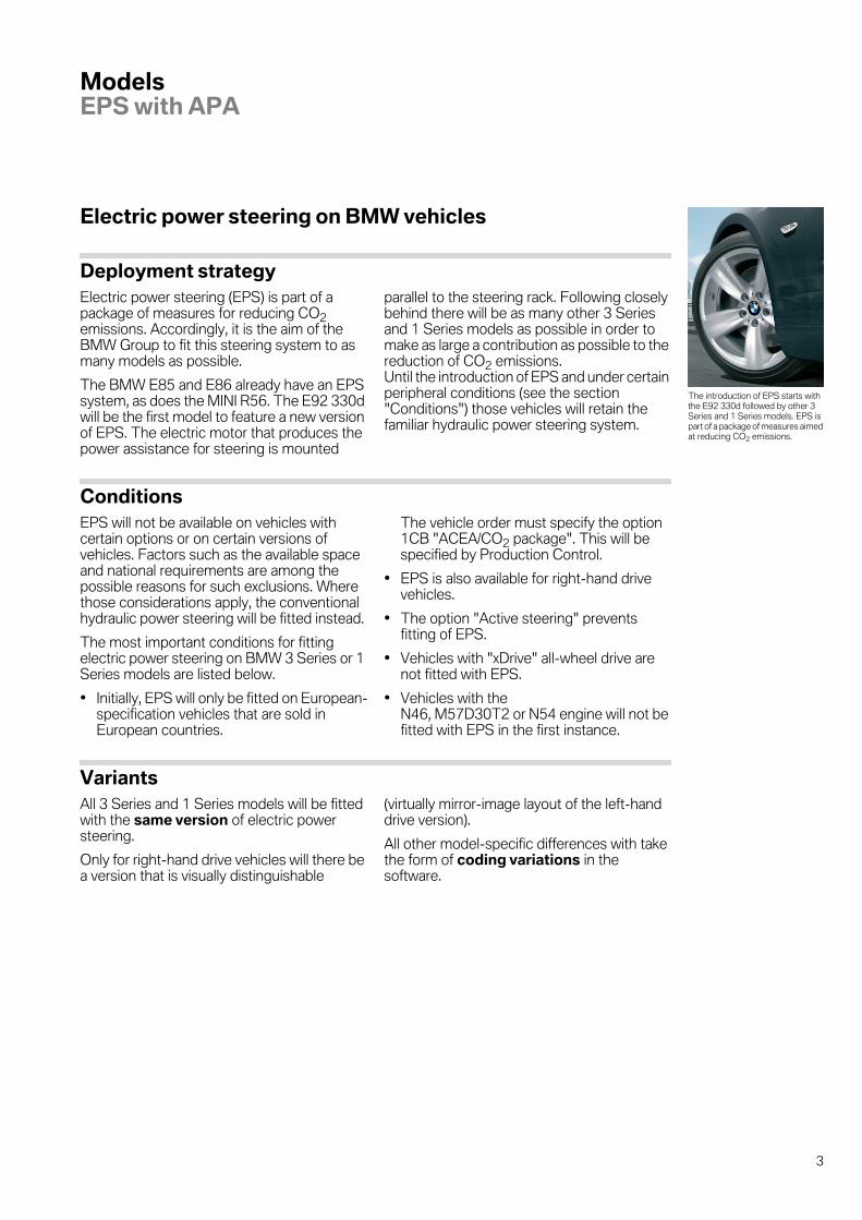
Deployment strategyElectric power steering (EPS) is part of apackage of measures for reducing CO2emissions. Accordingly, it is the aim of theBMW Group to fit this steering system to asmany models as possible.
The BMW E85 and E86 already have an EPSsystem, as does the MINI R56. The E92 330dwill be the first model to feature a new versionof EPS. The electric motor that produces thepower assistance for steering is mounted
parallel to the steering rack. Following closelybehind there will be as many other 3 Seriesand 1 Series models as possible in order tomake as large a contribution as possible to thereduction of CO2 emissions.Until the introduction of EPS and under certainperipheral conditions (see the section"Conditions") those vehicles will retain thefamiliar hydraulic power steering system.
ConditionsEPS will not be available on vehicles withcertain options or on certain versions ofvehicles. Factors such as the available spaceand national requirements are among thepossible reasons for such exclusions. Wherethose considerations apply, the conventionalhydraulic power steering will be fitted instead.
The most important conditions for fittingelectric power steering on BMW 3 Series or 1Series models are listed below.
• Initially, EPS will only be fitted on European-specification vehicles that are sold inEuropean countries.
The vehicle order must specify the option1CB "ACEA/CO2 package". This will bespecified by Production Control.
• EPS is also available for right-hand drivevehicles.
• The option "Active steering" preventsfitting of EPS.
• Vehicles with "xDrive" all-wheel drive arenot fitted with EPS.
• Vehicles with theN46, M57D30T2 or N54 engine will not befitted with EPS in the first instance.
VariantsAll 3 Series and 1 Series models will be fittedwith the same version of electric powersteering.
Only for right-hand drive vehicles will there bea version that is visually distinguishable
(virtually mirror-image layout of the left-handdrive version).
All other model-specific differences with takethe form of coding variations in thesoftware.
The introduction of EPS starts withthe E92 330d followed by other 3Series and 1 Series models. EPS ispart of a package of measures aimedat reducing CO2 emissions.
3

2
4

3
Introduction.EPS with APA.
Comparison with current steering systems
Hydraulic and electric power steering systemsThe main difference between the two types ofpower steering is in the method of generatingthe power assistance force that reduces theamount of force that the driver has to apply tothe steering wheel.
Hydraulic power steering systems feature apump that is driven either by a belt running offthe engine or by an electric motor. The pumpis part of a hydraulic system in which itgenerates the fluid pressure/flow that is usedto produce the power assistance for steering.
Electric power steering systems produce thepower assistance force directly by means ofan electric motor that transmits its torqueeither to the steering column or the steeringgear. Therefore, such systems generallyrequire extra gearing to connect the electricmotor to the existing steering systemcomponents.
Otherwise, the basic design of the steeringsystem is the same (e.g. rack-and-pinionsteering gear for both hydraulic and electricpower steering systems).
The steering characteristics, e.g. amount ofsteering force required, progression ofsteering force, feedback from the roadwheels,are subject to strict developmentspecifications that have resulted in continualoptimization of the hydraulic power steeringsystems so far used. In order that BMWowners continue to experience theoutstanding steering characteristics of BMWvehicles, a comprehensive specificationscatalogue was compiled that the new electricpower steering systems have to match up to.In addition, a vehicle with hydraulic powersteering frequently serves as the benchmarkfor a new steering system.
Versions of electric power steeringThe table below categorizes EPS systems onthe basis of the mounting position of the servounit consisting of electric motor and reductiongearing.
• EPS on BMW Z4:Servo unit on upper steering column inpassenger compartment, also called"column EPS" (C-EPS).
• EPS on MINI:Servo unit on pinion (transmission pointbetween steering column and steeringrack), also called "pinion EPS" (P-EPS).
• EPS with APA on BMW 3 Series or 1Series:Servo unit mounted parallel to steering rack.
With the advent of EPS, the methodof generating the power assistancefor steering changes from hydraulicto electrical means.EPS not only enables model-specific adaptation of steeringcharacteristics, it also offers otheradvantages for customers, theenvironment and car manufacturers.In contrast with active steering,vehicles with EPS do not have a splitsteering system, which is why EPScan superimpose an additionalsteering force but not change thesteering angle.
EPS with APA P-EPS C-EPS
Vehicles BMW 3 Series, 1Series(E9x, E87...)
MINI(R56)
BMW Z4(E85, E86)
Manufacturer ZF JTEKT ZF
Type ofelectric motor
Brushless DC motor Brushless DC motor Brushlessasynchronous motor
Mounting positionof electric motorand reductiongearing
Parallel to steering rack Pinion at transmissionpoint betweensteeringcolumn and steeringrack
Upper part of steeringcolumn
Design of reductiongearing
Belt and ball screwdrive
Worm shaft and gear Worm shaft and gear
5

3
It is only the combination of the latestgeneration of brushless DC motors withtransmission of the drive directly to the
steering rack that has enabled generation ofthe high steering rack forces that can berequired on the Series 3 and Series 1 models.
Distinction from active steeringThe electric motor of an EPS system iscapable of superimposing additional force ontop of the force applied by the driver. The EPSis able to determine the level and timing of thatforce independently of such factors as theengine speed.The rigid link between the steering wheel andthe front roadwheels that it steers remainsunchanged with electric power steering, i.e.the position of the steering wheel alwaysrelates exactly to a position of the frontroadwheels.
The electric motor in an active steeringsystem, by contrast, is capable ofsuperimposing a steering angle but not asteering force.
The steering train of an active steering systemis split by a double planetary gear.That enables the active steering to alter thesteering angle of the roadwheels without itbeing felt by the driver through the steeringwheel.In order that the wheels adopt the totalsteering angle produced by the steering wheelposition plus the superimposed adjustment, abracing force is required: the driver has to holdthe steering wheel firmly. A servo unit is alsorequired. This can only be of the hydraulic typeon active steering systems. Only hydraulicservo units are currently capable of providingthe combination of high positioning force andpositioning speed.
6

3
Motivation and features
Reasons for the introduction of electric power steering systemsThe use of electric power steering providesmany advantages for the BMW customer, theenvironment and the BMW Group as thevehicle manufacturer.
Interacting with the well-proven suspensionconcepts, a unique combination of drivingcomfort and dynamics is achieved. Thesteering properties (e.g. the level of steeringtorque assistance and damping) can be finelytuned by correspondingly programming theelectrical system while ensuring optimumadaptation to the different vehiclephilosophies.Thus, despite the use of identical mechanicalcomponents, the system will be capable ofperfect adaptation to models in both the 3Series and 1 Series.
Where more precise steering and betterhandling characteristics are desired for a moresports-style model, it can be achieved byreducing the amount of power assistance.Although the driver then has to apply slightlymore force to the steering wheel, thefeedback from the roadwheels gives the more"direct" feel desired.
By contrast, a greater degree of powerassistance is programmed for models whosesteering characteristics are to be morecomfort-orientated.
With the disappearance of the hydraulicsystem (consisting of pump, hoses, cooler,fluid, etc.), assembly of the steering on theproduction line is more straightforward for themanufacturer. The EPS steering system issupplied as a pre-assembled unit and fitted tothe vehicle as such. In addition, the EPS alsoeliminates the environmental hazard ofhydraulic fluid leakage.
Since, in contrast to hydraulic power steeringpumps, the electric motor is activated onlywhen required (when steering but not whendriving straight ahead) fuel consumption isreduced and the effective power output of thecombustion engine increased.The example figures below illustrate thedifference in power consumption between thetwo steering systems.
Power consumption in watts(approximate figures)
Electric power steering Hydraulic powersteering
Minimum(no steering movement, engineidling)
10 300-400
Maximum 1000 2000
7

3
Features of electric power steering
Improved handling dynamics
• Steering characteristics perfectly adaptedto vehicle model
• Active return (centring)
• Linear dynamics benefits of up to 2 kW.
Greater driving comfort
• Steering train isolated from suspensionvibration while still transmitting theimportant road feedback (different roadsurface conditions) to the driver
• Improved isolation of interference from theroad surface (less steering judder)
• Electronically controlled, speed-dependentpower-assistance (e.g. greater whenparking)
Greater driving safety:
• Servotronic function:EPS assists the driver to hold the correctline, particularly at high speeds, by providinga lower level of power assistance than at lowspeeds.
• Steering wheel backlash is reduced byactive speed-dependent damping. Thisfunction also reduces the vehicle'stendency to slew in response to abruptsteering wheel movements made by thedriver.
Better environmental credentials:
• Fuel saving of approx. 0.2 l per 100 km
• No possibility of leakage from the hydraulicsystem.
Simplifications for the vehiclemanufacturer
• Reduced assembly and inspectioncomplexity at the production plant as thesystem is supplied as a complete unit
• Reduced range of variants compared tohydraulic systems (pumps, hoses, steeringwheels)
• Easier tuning of power steering assistanceby programming
• High future potential: integration betweenvehicle systems (dynamic driving systems,driver assistance systems)
8

4
System overview.EPS with APA.
Mechanical design
The electric power steering is an absolutelyidentical fit with the previously used hydraulicpower steering as far as the connectionsbetween it and the vehicle are concerned.
For comparison, a hydraulic power steeringsystem and the new EPS with parallel-mounted motor are illustrated below.
The EPS consists of a steeringtorque sensor, EPS control unit,electric motor with position sensor,reduction gearing and steering rackwhich together form a pre-assembled unit.The mechanical links between theEPS system and the vehicle are thesame as with a hydraulic powersteering system.The EPS has electrical links with theDME, DSC, SZL, CAS andinstrument cluster.
1 - Hydraulic power steering on E92
Index Explanation Index Explanation
1 Hydraulic-fluid reservoir 4 Track rod
2 Steering column 5 Hydraulic power steering pump
3 Torsion bar and valve actuator 6 Steering rack
9

4
2 - Electric power steering with parallel-mounted motor on E92
Index Explanation Index Explanation
1 Steering rack 5 EPS control unit
2 Steering torque sensor 6 Electric motor with position sensor
3 Steering column 7 Reduction gear
4 Track rod
10

4
The EPS system essentially consists of thefollowing components, which are described indetail in the section "System components":
• Steering torque sensor
• EPS control unit
• Electric motor with position sensor
• Reduction gear
• Steering rack
3 Those components form a pre-assembled unit (often referred to as "EPSsteering rack assembly") that can only bereplaced as a complete unit. To do so, the unithas to be disconnected from the track rodsand the lower end of the steering column. 1
3 After a new EPS steering rack is fitted, afront wheel and tracking alignment check isrequired.The commissioning sequence involves codingthe EPS to match the vehicle model and thediagnosis function for learning the end-stoppositions. 1
3 - EPS rack-and-pinion steering box with parallel-mounted electric motor
Index Explanation Index Explanation
1 Ball-screw drive (part of reductiongearing)
7 Thrust piece
2 Rack 8 Signal and power lead for steeringtorque sensor
3 Pinion 9 EPS control unit
4 Steering torque sensor 10 Electric motor
5 Gaiter 11 Toothed-belt drive (part ofreduction gearing)
6 Track rod 12 Reduction-gear housing
11

4
Electrical system integration
Overview of bus system
4 - Bus system overview for EPS on E92
12

4
The LWS shown in the bus system overviewis the overall steering angle sensor, which is acomponent of the active steering system. This
is not part of the EPS system complex.Instead, the EPS uses the signals from thesteering-angle sensor integrated in the SZL.
Index Explanation Index Explanation
CAS Car access system EPS EPS control unit
DME Digital engine managementmodule
JB Junction box
DSC Dynamic stability control Kombi Instrument cluster
DSC-SEN DSC sensor SZL Steering column switch clusterwith steering-angle sensor
13

4
System circuit diagram
5 - System circuit diagram for EPS on E92
14
4
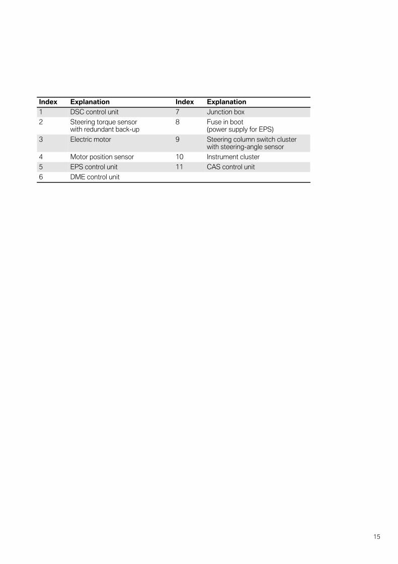
Index Explanation Index Explanation
1 DSC control unit 7 Junction box
2 Steering torque sensorwith redundant back-up
8 Fuse in boot(power supply for EPS)
3 Electric motor 9 Steering column switch clusterwith steering-angle sensor
4 Motor position sensor 10 Instrument cluster
5 EPS control unit 11 CAS control unit
6 DME control unit
15

4
16

5
Functions.EPS with APA.
Functional integration
EPS input variables
Steering column switch cluster (SZL)
Dynamic stability control (DSC)
Digital engine management module(DME)
Car Access System (CAS)
EPS output variables
Digital engine management module(DME) Instrument cluster (Kombi)
EPS offers BMW owners a packageof functions that improve drivingcomfort and safety.Those functions are: speed-dependent power steeringassistance, active steering-wheelreturn, active damping of steeringwheel backlash and activeroadwheel feedback.In the event of a fault, the EPSprevents operation of the electricmotor so that driver can steerwithout the assistance of the EPS.
Transmitter Steering column switchcluster with steering-anglesensor
Signal Steering angle set bydriver
Transmittedvia
PT-CAN
Receiver EPS control unit
Function Active steering-wheelreturn
Transmitter Dynamic stability controlwith DSC sensor
Signal Road speed and othervariables that describethe driving situation
Transmittedvia
PT-CAN
Receiver EPS control unit
Function Steering power assistance,active roadwheel feedback
Transmitter Digital motor electronics
Signal Engine running
Transmittedvia
PT-CAN
Receiver EPS control unit
Function Status control
Transmitter Car access system
Signal Terminal 15 status
Transmittedvia
PT-CAN
Receiver EPS control unit
Function Status control
Transmitter EPS control unit
Signal Demand for greatercooling capacity
Transmittedvia
PT-CAN
Receiver Digital motor electronics
Function Control of electric fan
Transmitter EPS control unit
Signal Request for failuremessage
Transmittedvia
PT-CAN, Junction box, K-CAN
Receiver Instrument cluster
Function Control of warning andindicator lamps
17
5
DME functions used by EPS
Intelligent alternator control by thedigital engine management
With the advent of "intelligent alternatorcontrol" (IGR) on the DME as an additionalmeans of CO2 reduction, the alternatorvoltage is adjusted according to the drivingsituation and battery charge level. Therefore,there will be periods in which the electricalsystem voltage is at the level that has beennormal up to now (approx. 13.8 V). However,there will also be situations in which thevoltage drops to around or just below 12 V.
The EPS components, and in particular theelectric motor, are rated for a power supply of12 V. At that level, the requirements in termsof maximum steering power assistance andspeed are satisfied.
If the maximum EPS output were demandedat an alternator voltage of 12 V, the highcurrent draw by the electric motor wouldproduce a voltage drop on the EPS powersupply line. The consequence would be anEPS input voltage of substantially below 12 Vand, therefore, a reduced level of steeringpower assistance.
In order to prevent such an undesirablesituation occurring, there is an additional IGRfunction for the EPS that is implementedwithout additional exchange of signals with theEPS and comprises the following features:
• Observation of whether an operatingstatus exists in which high EPS output isrequired.The bus signals indicating steering anglerate of change and road speed aremonitored for that purpose. A high level ofEPS output is identified when the steeringangle rate of change is high at the sametime as the road speed is low.
• Action:Increase of alternator output and temporaryincrease of electrical system voltage whenhigh EPS output is detected.
This function ensures that the power supply atthe EPS input terminals always provides atleast the rated voltage of 12 V regardless, to agreat extent, of other variables.
3 Detecting statuses involving high EPSoutput and raising the electrical systemvoltage constitute a control cycle that iscompleted within 2 seconds at most. As it isalso an infrequent situation, it is unlikely that itwill be the subject of customer complaints.If a particularly observant customer complainsof momentarily reduced power steeringassistance, this control cycle may possibly bethe cause. If there are repeated complaints,performing a diagnosis on the power supply isadvisable. 1
18

5
EPS functions in detail
Overview
1 - Overview of EPS functionson E92
Index Explanation
1 Input
2 EPS control unit
3 Output
S1 Input signals for EPS control and modulation functions- Steering force applied by driver- Road speed and other variables that describe the driving situation- Steering angle, steering angle rate of change
S2 Input signals for EPS status control- Terminal 15 on/off- Engine running/not running
F1 "Speed-dependent power steering assistance" function
F2 "Active steering wheel return" function
F3 "Active damping" function
F4 "Active roadwheel feedback" function
F5 "Status control" function
F6 "Co-ordination of specified settings" function
S3 Output signal of EPS control and modulation functions: control of electric motor
S4 Output signal of EPS status control:- Demand for higher cooling capacity- Control of warning and indicator lamps
19

5
Speed-dependent power steering assistanceThe Servotronic function that is onlyachievable by means of additional systemcomplexity on hydraulic steering systems isimplemented in the form of software on theelectric power steering system and istherefore available with EPS.The customer expects the lightest andsmoothest steering movement possible whenmanoeuvring or parking into spaces. Lesssensitive steering setup is required whendriving at high speed so that the vehicle can bekept on course more effectively.
Based on the sensor signals indicating thevehicle's road speed and the steering torqueapplied by the driver, the EPS provides a highlevel of power steering assistance at lowspeeds and when stationary (maximumconvenience).
At high speeds on the other hand, the EPSdemands greater steering force from thedriver by reducing the level of power steeringassistance. This helps the driver to hold aconstant line.
As can be seen from the graph, the level ofpower assistance is computed on the basisnot only of vehicle speed but also of thesteering torque applied by the driver. If thedriver applies a small amount of turning forceto the steering wheel, the assistance from theEPS also initially remains at a relatively lowlevel. This produces excellent self-centringcharacteristics, i.e. the steering does not reactover-sensitively from the straight-aheadposition.If the driver applies greater force to thesteering wheel, there is a smooth transition toa steeper curve gradient. As a result, the driverobtains the expected high degree ofassistance when making abrupt steeringmovements or tight manoeuvres.The characteristics described here have been
adopted by the EPS from the familiar hydraulicsteering systems.
The transition between the curves is notabrupt but progressive. The EPS calculatesappropriate transitional levels wherenecessary.
The steering characteristics of the EPS on theBMW 3 Series and 1 Series cannot bechanged by the driver as is possible on othervehicles. The SPORTS button such as isfound in the BMW E85 or E86 is not availableon these models and neither does the"Settings" menu on the Central InformationDisplay provide the facility for suchadjustments.
2 - EPS speed-dependent power steering assistance
Index Explanation
1 Steering torque applied by driver
2 Power assistance torque providedby EPS
3 Vehicle road speed equal to zero
4 Vehicle road speed increases
5 Vehicle road speed at maximum
20

5
Active steering-wheel returnIn addition to the natural self-centringcharacteristics inherent in the steering andsuspension systems, this function assistssteering-wheel return by appropriateoperation of the electric motor.
The following signals are required for thispurpose:
• Road speed
• Steering torque applied by driver
• Steering angle and
• Steering angle rate of change
However, the steering angle signal is onlyrequired for calibration with the electric-motorposition sensor in order to determine thetarget position for steering-wheel return(steering angle equal to zero). Thereafter, theactive steering-wheel return function uses theelectric-motor position sensor signal as it hasa higher resolution than the steering anglesensor signal and thus enables more precisecontrol.
If the steering-angle sensor signal is notavailable, e.g. due to a fault on the SZL, theactive steering-wheel return function cannotoperate. The other EPS functions remainactive. Customers may possibly describe theresulting vehicle behaviour as "pulling to oneside" because the steering wheel does notreturn to the straight-ahead position asprecisely as usual.
3 If a customer complains of the car "pullingto one side" the possible causes to be
considered include not only a mechanicalproblem with the suspension/steering but alsoa signal or communication fault between theEPS and the steering column switch cluster/steering-angle sensor. In such a situation, theEPS is unable to provide the active steering-wheel return function and this may beperceived by the customer as the vehicle"pulling to one side".Therefore, before checking the wheelalignment, the EPS fault memory should bechecked and, if necessary, the stored testingsequence followed in order to make certainthe signal from the steering-angle sensor ispresent. 1
The necessity for activation of the activesteering-wheel return function arises when,for example, the driver allows the steeringwheel to slip when exiting a corner. The signalvalues reflecting that situation which the EPSuses to detect the situation are:
• Steering angle clearly not equal to zero and
• Steering torque applied by driverapproximately equal to zero
The electric motor is then operated by theEPS so as to generate a return force thatproduces smooth return of the steering wheelto a position close to the straight-aheadposition.
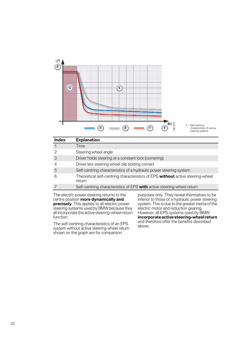
The clearly perceptible improvementcompared with the self-centringcharacteristics of hydraulic power steeringsystems is evident from the graph below.
21
5
The electric power steering returns to thecentre position more dynamically andprecisely. This applies to all electric powersteering systems used by BMW because theyall incorporate the active steering-wheel returnfunction.
The self-centring characteristics of an EPSsystem without active steering wheel returnshown on the graph are for comparison
purposes only. They reveal themselves to beinferior to those of a hydraulic power steeringsystem. This is due to the greater inertia of theelectric motor and reduction gearing.However, all EPS systems used by BMWincorporate active steering-wheel returnand therefore offer the benefits describedabove.
3 - Self-centringcharacteristics of varioussteering systems
Index Explanation
1 Time
2 Steering wheel angle
3 Driver holds steering at a constant lock (cornering)
4 Driver lets steering wheel slip (exiting corner)
5 Self-centring characteristics of a hydraulic power steering system
6 Theoretical self-centring characteristics of EPS without active steering-wheelreturn
7 Self-centring characteristics of EPS with active steering-wheel return
22

5
Active dampingThe undesirable steering-wheel movementsto be damped can be produced either byinadvertent steering input by the driver orfeedback from the road/roadwheels.
Damping roadwheel feedback
The design of the front suspension (double-link Macpherson strut suspension) on its ownensures that vertical wheel movementsproduce very little lateral force on the trackrods.
Due to the low ratio of the reduction gear bywhich the electric motor is connected to thesteering rack, the inertia of the electric motoralso has a damping effect on the forces andmovements transmitted from the roadwheelsto the steering wheel. Those mechanicaldamping effects are supplemented by anelectronic damping function on the part of theEPS. It analyses the movements of thesteering rack (using the signals from theelectric-motor position sensor) and operatesthe electric motor accordingly in response.
This means that feedback from external forcesis transmitted in controlled amounts to thesteering wheel so that, on the one hand, thedriver obtains sufficient information about thenature of the road surface, but on the other,undesirably extreme steering wheel backlashis prevented.
Damping steering input from driver
Particularly at high speeds, unintentional jerkymovements of the steering wheel by the driverhave a negative effect on vehicle handlingstability. So-called "snatching" of the steeringwheel can, under certain circumstances,cause the vehicle to start rocking, which canlead to snaking and the driver ultimately losingcontrol of the vehicle if corrective action is nottaken quickly enough.
The EPS detects such steering input andoperates the electric motor so as tosubstantially damp the movements,particularly at high speeds. As a result, vehiclerocking is prevented.
23

5
4 - Damping of steering inputby EPS
Index Explanation
1 Time
2 Steering wheel angle
3 Steering angle progression (steering input by driver, "snatching" the steering wheel)
4 Yaw rate
5 Theoretical vehicle response without active damping: the turning action followingthe steering input is progressively amplified at high vehicle speed.
6 Desirable vehicle response with active damping: the turning action is heavilydamped even at high vehicle speeds.
24

5
Active roadwheel feedbackPartly due to the damping effect of the inertiaof the electric motor, an EPS system caninherently not provide as direct feedbackabout the nature of the road surface as ahydraulic power steering system.In order to obtain virtually identical roadwheelfeedback characteristics on vehicles with EPS,
the EPS analyses information that describesthe vehicle's dynamic handling situation. Fromthat information, the EPS computes additional"EPS road surface data". As a result, the driverobtains better roadwheel feedbackcharacteristics which are very similar to thoseof a hydraulic power steering system.
Status controlThe EPS status control function makes theoverriding decision as to whether operation ofthe electric motor is permissible or not. Itproduces a clearance signal that is sent to theEPS function that is co-ordinating thesubordinate specified settings of the controland modulation functions.
The conditions for allowing operation are thefollowing:
• Ignition must be switched on
• Engine must be running
• There must be no EPS input signal faults orEPS internal faults present
The response to detected faults describedbelow represents an exception.
Shutdown in the event of faults
A primary aim in the development of the EPSwas to ensure that vehicle response in theevent of faults would remain manageable bythe driver. Therefore, under no circumstancesmust a sudden high steering force in eitherdirection be allowed to occur. For that reason,the EPS has numerous monitoring functionsfor detecting faults on the sensors, actuatorsand associated systems that are involved inEPS operation.
All fault statuses in which reliable and correctcontrol of the electric motor is not possibleresult in the disabling of motor operation and,
therefore, shutdown of the EPS functions. Theconsequence of that is that the driver nolonger benefits from the convenience ofpower-assisted steering. More importantly,however, incorrect control of the electricmotor is prevented.
3 The loss of power steering assistance inthe event of faults constitutes an intendedsystem response on the part of the EPS.Although such a response may be slightlyunnerving for the driver, the vehicle remainsfully steerable with greater physical effort. 1
Loss of power steering assistance in the eventof faults occurs both with electric andhydraulic power steering. The two systemsthus also behave in a similar manner inresponse to faults.
In such a fault situation, the following warninglamp lights up on the instrument cluster:
In the case illustrated, the driver is also notifiedof the fact that power steering assistance fromthe EPS is no longer available by display of theappropriate Check Control symbol togetherwith the explanatory message on the CentralInformation Display.
5 - Warning lamp indicatingfailure of EPS system
25
5
Co-ordination of specified settingsThe specified settings for the control andmodulation functions for operating the electricmotor are co-ordinated at a central point bythe EPS software. If a clearance signal fromthe status control function is present, theindividual specified settings are normallyadded together and signalled as a totalvalue.
In certain transitional situations thespecified settings are filtered before they aresignalled.
The following are examples of such cases:
• The EPS goes into operation after theengine is started. The power assistancetorque is increased progressively until thedesired level is reached.
• The EPS reduces the power steeringassistance for function-related reasons(see also the section "Supplementaryfunctions").
In the event of a fault the control signal forthe electric motor is abruptly cancelledinstead of being filtered in order to preventincorrect operation as quickly as possible.
Supplementary functionsThe functions described below areencountered only rarely in special operatingsituations. The information given here canhelp to distinguish those special operatingstatuses, which do not require repairs, fromgenuine faults when handling complaints fromcustomers.
Protection against overload
The EPS reduces the degree of powersteering assistance if the temperature of EPScomponents becomes too high. By limitingmotor operation, the amount of heatgenerated by the EPS itself is also limited,thereby protecting the components againstexcessive thermal stress.This action starts to come into effect from atemperature of approx. 100 °C and escalatesto the point where power steering assistanceis reduced to zero at a temperature of 115 °C.Upwards of a certain degree of functionrestriction, the warning light on the instrumentcluster is switched on (see the section"Shutdown in the event of faults") and a faultregistered in the fault memory.
In addition to reducing power steeringassistance, the EPS also requests higherelectric fan output from the DME in order toproduce a greater cooling effect.
This type of overload can occur at highambient temperatures combined withsimultaneous high degrees of steering activity,especially when stationary.
Another overload situation can occur if anattempt is made to turn the front wheelsagainst a solid obstacle (e.g. a kerbstone). Ifthis situation occurs repeatedly at shortintervals, the degree of power steeringassistance is similarly reduced. This firstlyprotects the EPS components againstexcessive mechanical stresses, and secondlysignals to the driver that there is a solid objectpreventing the wheels turning.The EPS detects such situations bycomparing the control signals to the electricmotor with the motion of the motor.
3 The EPS reduces the power steeringassistance in overload situations. If customercomplaints are received, the customer shouldbe questioned as to the situation in which thesymptoms occurred before commencing anyrepair work.
If necessary enlighten the customer as to theway in which these protective functionsoperate. 1
26

5
End stop as software function
Although the EPS steering gear alsoincorporates mechanical end stops, there is afunction that steeply reduces the level ofpower assistance shortly before themechanical end stops are reached. Althoughthe driver will perceive this as increased
steering resistance, it makes turning thewheels to full lock much smoother overall.
In addition, this function reduces the stresseson mechanical and electrical components ofthe steering system and thus contributes tothe achievement of long service life combinedwith reliable operation.
OutlookThe EPS exclusively uses software algorithmsto decide on the timing, level and timeprogression of electric motor operation andthe resulting forces applied to the frontwheels/steering wheel.That means that the EPS can also control theelectric motor on the basis of signals producedby external demand originators (control units).
That possibility can be made use of by vehiclesystems in future to assist the driver in certainsituations by selectively applying a turningforce to the steering wheel. Conceivablesystems would be those involved in stabilitycontrol or driver assistance.
27

5
28

6
System components.EPS with APA.
EPS components in detail
The essential components of the EPS systemare described in detail below:
• Steering torque sensor
• EPS control unit
• Electric motor with position sensor
• Reduction gear
• Steering rack
Steering torque sensorThe amount of power steering assistanceprovided by the EPS is controlled in responseto the driver's requirement. The driver'srequirement equates to the force/torqueapplied by the driver to the steering wheel.
The steering torque sensor supplies preciselythat information and is fitted at the junctionbetween lower steering column and steeringgear for that purpose.
The steering torque sensor providesthe EPS control unit with informationabout the steering torque applied bythe driver in the form of an inputsignal. The EPS control unit usesthat signal and other input signals tocalculate the power assistancetorque and operates the electricmotor accordingly. The torqueproduced by the electric motor isadded by way of the reduction gearto the steering torque applied by thedriver. The total torque is convertedby the steering rack into steeringforce at the front wheels.
1 - Steering torque sensor forEPS with APA
Index Explanation Index Explanation
1 Sensor unit with electronic analysercircuitry
4 Coil spring
2 Torsion bar (top end) 5 Ring magnet
3 Input shaft
29
6
Rotation of the input shaft (3) and ring magnet(5) is detected and electronically analysed bythe sensor unit (1). The fundamental sensingprinciple applied is called the Hall effect.As the rigidity of the torsion bar (2) inside theinput shaft is known, the electronic circuitrycan calculate the amount of torque appliedfrom the degree of twist.The steering torque is then digitallytransmitted to the EPS control unit via a directcable connection.
The sensor is provided with redundantback-up (a second identical sensor) so thatsystem availability in the event of sensor failureis improved. If an unacceptable degree ofdivergence between the two sensors isdetected during operation, the systemcontinues to operate on the basis of the moreplausible of the two signals and full EPSfunctionality is maintained.If the fault status remains present at the end ofthe driving cycle, a fault memory entry isgenerated and the EPS does not operatewhen the next driving cycle starts.
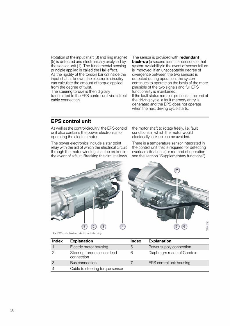
EPS control unitAs well as the control circuitry, the EPS controlunit also contains the power electronics foroperating the electric motor.
The power electronics include a star pointrelay with the aid of which the electrical circuitthrough the motor windings can be broken inthe event of a fault. Breaking the circuit allows
the motor shaft to rotate freely, i.e. faultconditions in which the motor wouldelectrically lock up can be avoided.
There is a temperature sensor integrated inthe control unit that is required for detectingoverload situations (for method of operationsee the section "Supplementary functions").
2 - EPS control unit and electric motor housing
Index Explanation Index Explanation
1 Electric motor housing 5 Power supply connection
2 Steering torque sensor leadconnection
6 Diaphragm made of Goretex
3 Bus connection 7 EPS control unit housing
4 Cable to steering torque sensor
30

6
The housing of the EPS control unit (and theelectric motor) is located in a position exposedto large temperature fluctuations and highexternal moisture levels. Therefore, there is adiaphragm made of Goretex on thehousing that equalizes the pressure differencebetween the inside and outside of the housingbut still prevents moisture intrusion at thatpoint.
On the EPS control unit and electric motorhousing there are also the following EPSelectrical connections:
• Power supply for the EPS
• Bus connection (PT-CAN inc. wake-up line)
• Power supply and signal line for steeringtorque sensor
3 If the EPS steering rack assembly has tobe replaced, only the power supply and busconnection have to be disconnected and notthe connection for the steering torque sensor.1
3 If a customer complains of inadequatepower steering assistance, it can be due to avoltage drop across the power supplyconnection.Therefore, in such cases the power supplyconnection should be checked for corrosion.1
31
6
Electric motor with position sensorThe essential function of the electric motor isto generate the required torque calculatedby the EPS control unit.
The type of electric motor used is abrushless DC motor (made by Siemens).Although it is powered by direct current, itsmethod of operation is based on that of an ACsynchronous motor. The power electronics inthe EPS control unit convert the power supplyvoltage (DC voltage) into phase voltages so asto produce a rotating field at the phasewindings.
Only this type of motor combines the followingcharacteristics that are decisive for use in anEPS system:
• Constantly high torque over a wide range ofspeeds
• High efficiency
• Low wear
• Long service life
• High thermal load capacity
• Small external dimensions
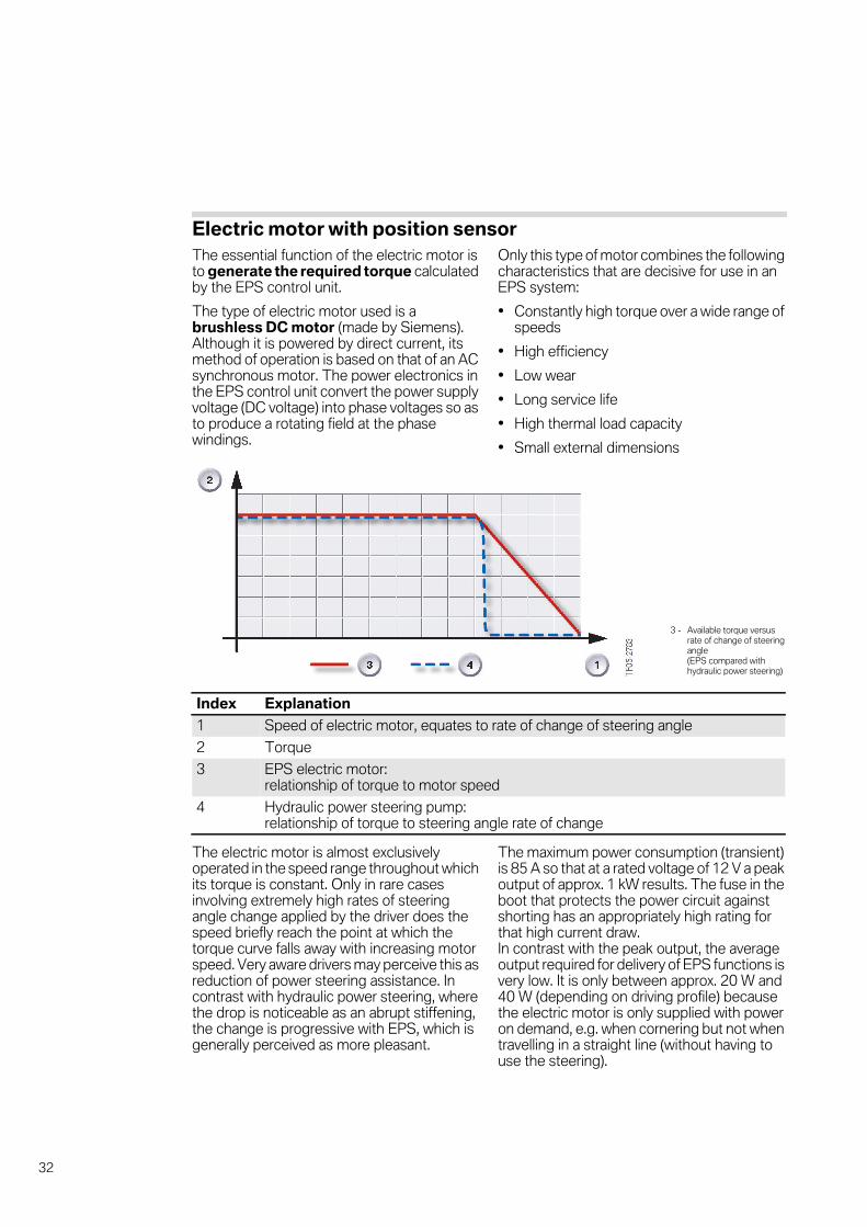
The electric motor is almost exclusivelyoperated in the speed range throughout whichits torque is constant. Only in rare casesinvolving extremely high rates of steeringangle change applied by the driver does thespeed briefly reach the point at which thetorque curve falls away with increasing motorspeed. Very aware drivers may perceive this asreduction of power steering assistance. Incontrast with hydraulic power steering, wherethe drop is noticeable as an abrupt stiffening,the change is progressive with EPS, which isgenerally perceived as more pleasant.
The maximum power consumption (transient)is 85 A so that at a rated voltage of 12 V a peakoutput of approx. 1 kW results. The fuse in theboot that protects the power circuit againstshorting has an appropriately high rating forthat high current draw.In contrast with the peak output, the averageoutput required for delivery of EPS functions isvery low. It is only between approx. 20 W and40 W (depending on driving profile) becausethe electric motor is only supplied with poweron demand, e.g. when cornering but not whentravelling in a straight line (without having touse the steering).
3 - Available torque versusrate of change of steeringangle(EPS compared withhydraulic power steering)
Index Explanation
1 Speed of electric motor, equates to rate of change of steering angle
2 Torque
3 EPS electric motor:relationship of torque to motor speed
4 Hydraulic power steering pump:relationship of torque to steering angle rate of change
32

6
Demand-based operation of the electric motoris the main reason why the fuel consumptionof vehicles with EPS is around 0.2 l / 100 kmless than that of vehicles with hydraulic powersteering. And on the other hand, the powerthat would otherwise be required to constantlydrive the power steering pump is now almostentirely available as additional motive powerfor the vehicle. Depending on the situation,there can be a linear dynamics gain of up to 2kW.
A second important component is actually onthe circuit board of the EPS control unit but islocated directly adjacent to the electric motorshaft: the motor position sensor. In that waythe motor position sensor can directly signalthe electric motor's rotor position to the EPScontrol unit. As the electric motor is rigidlyconnected to the steering rack by means ofthe reduction gearing, the EPS control unitcan deduce the position of the roadwheels
and the steering angle from the rotor position.After first calibrating the straight-aheadposition with the aid of the signal from thesteering angle sensor, the motor positionsensor signal is subsequently used for theEPS functions (e.g. "active steering-wheelreturn"). The reason for this is the higherresolution of the motor position sensor signal.
The sensing principle applied by the motorposition sensor is identical with that used bythe steering torque sensor. Both consist ofHall-effect sensor units adjacent to whichthere is a rotating magnet. The steering torquesensor is designed to detect small degrees oftwist, while the motor position sensor mustdetect large amounts of rotation (a completerevolution must be measurable). The motorposition sensor is also duplicated, though inthis case the duplicate unit has a differentresolution in order to be able to pick up bothfast and slow movements effectively.
Reduction gearThe reduction gearing transmits the torquegenerated by the electric motor to the steeringrack, thereby applying steering force to thefront wheels.
The overall transmission ratio is approximately20 revolutions of the electric motor to onerevolution of the steering wheel. That lowgearing ratio combined with the high torque ofthe electric motor makes it possible togenerate the required steering rack forces.
The low ratio combined with the rotating massof the electric motor also has a damping effecton feedback from the road and roadwheels (asdescribed in the section "Active damping").
The reduction gearing consists of thefollowing two constituent assemblies:
• belt drive and
• ball screw drive
33
6
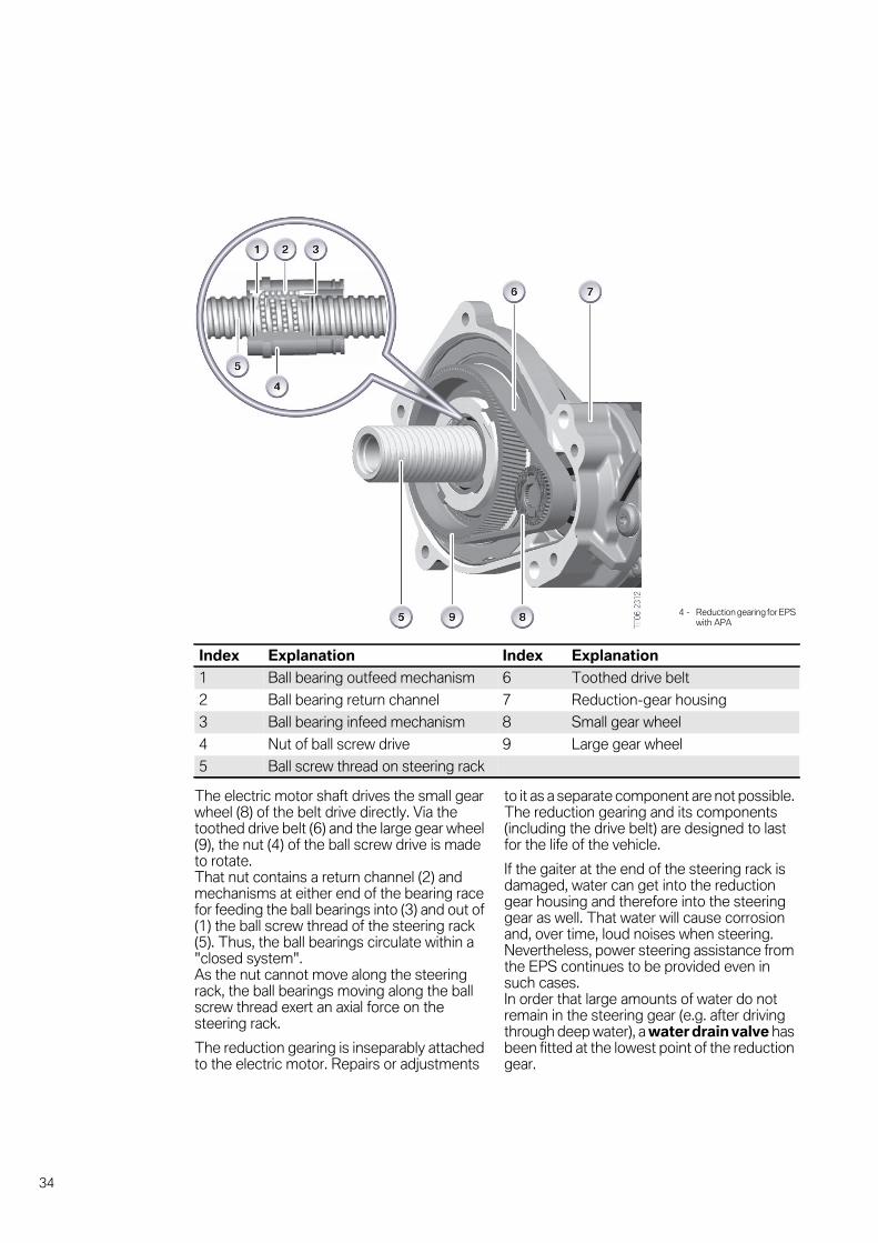
The electric motor shaft drives the small gearwheel (8) of the belt drive directly. Via thetoothed drive belt (6) and the large gear wheel(9), the nut (4) of the ball screw drive is madeto rotate.That nut contains a return channel (2) andmechanisms at either end of the bearing racefor feeding the ball bearings into (3) and out of(1) the ball screw thread of the steering rack(5). Thus, the ball bearings circulate within a"closed system".As the nut cannot move along the steeringrack, the ball bearings moving along the ballscrew thread exert an axial force on thesteering rack.
The reduction gearing is inseparably attachedto the electric motor. Repairs or adjustments
to it as a separate component are not possible.The reduction gearing and its components(including the drive belt) are designed to lastfor the life of the vehicle.
If the gaiter at the end of the steering rack isdamaged, water can get into the reductiongear housing and therefore into the steeringgear as well. That water will cause corrosionand, over time, loud noises when steering.Nevertheless, power steering assistance fromthe EPS continues to be provided even insuch cases.In order that large amounts of water do notremain in the steering gear (e.g. after drivingthrough deep water), a water drain valve hasbeen fitted at the lowest point of the reductiongear.
4 - Reduction gearing for EPSwith APA
Index Explanation Index Explanation
1 Ball bearing outfeed mechanism 6 Toothed drive belt
2 Ball bearing return channel 7 Reduction-gear housing
3 Ball bearing infeed mechanism 8 Small gear wheel
4 Nut of ball screw drive 9 Large gear wheel
5 Ball screw thread on steering rack
34

6
3 If a defective gaiter is discovered, it shouldbe replaced so as to prevent water enteringthe steering gear. At the same time asreplacing the gaiter, the water drain valve atthe lowest point of the reduction gear shouldalso be replaced and is included in the repairkit. 1
3 Corrosion on the moving parts of thesteering gear does not normally result inheavy steering.
Instead, corrosion is frequently a cause ofnoises from the steering mechanism.If customers complain of loud steering noisesand if they are definitely attributable to theEPS steering rack, the complete EPS steeringrack assembly must be replaced. 1
Steering rackThe steering rack of the EPS system has thesame function as that of a hydraulic powersteering system.It converts the steering force applied by thedriver combined with the power steeringassistance provided by the EPS into a forceapplied to the track rods. Ultimately, thatresults in steering movements by the frontwheels.
The design and dimensions of the steeringrack are such that the design of the othervehicle components only required marginaladjustments in order to enable the use ofelectric power steering.In particular, the points of attachment to thewheels by way of the track rods and with thesteering column are absolutely identical withthose used up to now with the hydraulic powersteering.
The track rod also has the same gearing ratio.Accordingly, the gearing ratio of the steeringsystem as a whole is identical regardless of thepower assistance method used.
As with hydraulic power steering systems,there is a thrust piece at the point where thepinion engages in the rack. It guides the rackand also serves as a means of adjusting theentire unit at the factory.
3 Adjustment of the steering rack andpinion using the thrust piece is a once-onlyoperation carried out during production. Thatadjustment cannot and must not beperformed at a dealership! 1
The thrust piece in this EPS system actspurely as a spring mechanism without ahydraulic bearing.
35

6
36

7
Service information.EPS with APA.
Important points for servicing and repairs
Replacing an EPS system3 The EPS components consisting of- steering torque sensor- EPS control unit- electric motor with position sensor- reduction gear and- steering rackform a single unit (often referred to as "EPSsteering rack assembly") that can only bereplaced as a complete unit. To do so, the unit
has to be disconnected from the track rodsand the lower end of the steering column. 1
3 After a new EPS steering rack is fitted, afront wheel and tracking alignment check isrequired. The commissioning sequenceinvolves coding the EPS to match the vehiclemodel and the diagnosis function for learningthe end-stop positions. 1
Intelligent alternator control and EPS3 Detecting statuses involving high EPSoutput and raising the electrical systemvoltage constitute a control cycle that iscompleted within 2 seconds at most. As it isalso an infrequent situation, it is unlikely that itwill be the subject of customer complaints.
If a particularly observant customer complainsof momentarily reduced power steeringassistance, this control cycle may possibly bethe cause. If there are repeated complaints,performing a diagnosis on the power supply isadvizable. 1
Active steering wheel reset3 If a customer complains of the car "pullingto one side" the possible causes to beconsidered include not only a mechanicalproblem with the suspension/steering but alsoa signal or communication fault between theEPS and the steering column switch cluster/steering-angle sensor. In such a situation, theEPS is unable to provide the active steering-wheel return function and this may be
perceived by the customer as the vehicle"pulling to one side".Therefore, before checking the wheelalignment, the EPS fault memory should bechecked and, if necessary, the stored testingsequence followed in order to make certainthe signal from the steering-angle sensor ispresent. 1
Protection against overload3 The EPS reduces the power steeringassistance in overload situations. If customercomplaints are received, the customer shouldbe questioned as to the situation in which the
symptoms occurred before commencing anyrepair work.
If necessary enlighten the customer as to theway in which these protective functionsoperate. 1
Shutdown in the event of faults3 The loss of power steering assistance inthe event of faults constitutes an intendedsystem response on the part of the EPS.
Although such a response may be slightlyunnerving for the driver, the vehicle remainsfully steerable with greater physical effort. 1
This Service information can also befound in the sections "Systemoverview", "Functions" and "Systemcomponents".
37

7
Electrical connections3 If the EPS steering rack assembly has tobe replaced, only the power supply and busconnection have to be disconnected and notthe connection for the steering torque sensor.1
3 If a customer complains of inadequatepower steering assistance, it can be due to avoltage drop across the power supplyconnection.Therefore, in such cases the power supplyconnection should be checked for corrosion.1
Step-down gear3 If a defective gaiter is discovered, it shouldbe replaced so as to prevent water enteringthe steering gear. At the same time asreplacing the gaiter, the water drain valve atthe lowest point of the reduction gear shouldalso be replaced and is included in the repairkit. 1
3 Corrosion on the moving parts of thesteering gear does not normally result inheavy steering.
Instead, corrosion is frequently a cause ofnoises from the steering mechanism.If customers complain of loud steering noisesand if they are definitely attributable to theEPS steering rack, the complete EPS steeringrack assembly must be replaced. 1
Thrust piece3 Adjustment of the steering rack andpinion using the thrust piece is a once-onlyoperation carried out during production. That
adjustment cannot and must not beperformed at a dealership! 1
38
8
SummaryEPS with APA.
Points to remember
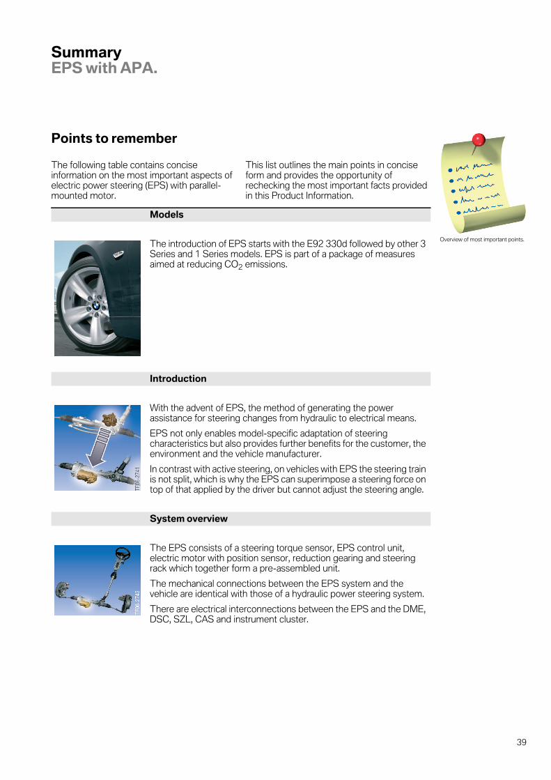
The following table contains conciseinformation on the most important aspects ofelectric power steering (EPS) with parallel-mounted motor.
This list outlines the main points in conciseform and provides the opportunity ofrechecking the most important facts providedin this Product Information.
Overview of most important points.
Models
The introduction of EPS starts with the E92 330d followed by other 3Series and 1 Series models. EPS is part of a package of measuresaimed at reducing CO2 emissions.
Introduction
With the advent of EPS, the method of generating the powerassistance for steering changes from hydraulic to electrical means.
EPS not only enables model-specific adaptation of steeringcharacteristics but also provides further benefits for the customer, theenvironment and the vehicle manufacturer.
In contrast with active steering, on vehicles with EPS the steering trainis not split, which is why the EPS can superimpose a steering force ontop of that applied by the driver but cannot adjust the steering angle.
System overview
The EPS consists of a steering torque sensor, EPS control unit,electric motor with position sensor, reduction gearing and steeringrack which together form a pre-assembled unit.
The mechanical connections between the EPS system and thevehicle are identical with those of a hydraulic power steering system.
There are electrical interconnections between the EPS and the DME,DSC, SZL, CAS and instrument cluster.
39

8
Functions
EPS offers BMW owners a package of functions that improve drivingcomfort and safety.Those functions are: speed-dependent power steering assistance- active steering-wheel return- active steering-wheel damping- active roadwheel feedback.
In the event of faults, the EPS prevents operation of the electric motorso that the driver can still steer without the assistance of the EPS.
System components
The steering torque sensor provides the EPS control unit withinformation about the steering torque applied by the driver in the formof an input signal. The EPS control unit uses that signal and other inputsignals to calculate the power assistance torque and operates theelectric motor accordingly. The torque produced by the electric motoris added by way of the reduction gear to the steering torque applied bythe driver. The total torque is converted by the rack and pinion steeringgear into steering force at the front wheels.
40

9
Test questions.EPS with APA.
Questions
In this section, you have a chance to test whatyou have learned by answering questions on
the subject of electric power steering withparallel-mounted motor.
1. How does EPS differ from active steering?
4 EPS superimposes a steering force and a steering angle on the steering requirement fromthe driver.
4 There is no difference between EPS and active steering.
4 The EPS electric motor superimposes a steering force, whereas the active steering electricmotor superimposes a steering angle on the requirement from the driver.
4 All active steering systems include EPS.
2. What functions does EPS provide on BMW vehicles?
4 Speed-dependent power steering assistance (Servotronic)
4 Damping of undesirable steering wheel movements.
4 Yaw rate control (especially when vehicle is skidding)
4 Changing steering characteristics on "Settings" menu on Central Information Display.
4 Variable steering gear ratio (speed-dependent)
4 Active steering-wheel return to straight-ahead position
3. Which of the following statements about repairs to the EPS on BMW vehicles arecorrect?
4 The components such as the control unit, electric motor, reduction gear and steeringtorque sensor can be replaced individually.
4 The EPS consisting of EPS control unit, electric motor with position sensor, reductiongearing, steering rack and steering torque sensor, can only be replaced as a complete unit.
4 After replacing the EPS, the following operations must be carried out:end-stop learning sequence, track alignment, coding of EPS control unit.
4 After being replaced, the EPS learns the positions of the end stops itself while the vehicleis being driven.
4. Which of the following statements about integration the EPS with other systemson BMW vehicles are correct?
4 The EPS is entirely autonomous and capable of functioning without any other systems onthe vehicle.
4 There are electrical interconnections between the EPS and the DME, DSC, SZL, CAS andinstrument cluster. The EPS can only function correctly within that system complex.
4 The EPS is mechanically adapted to the vehicle and its suspension system so as to achievethe desired dynamic handling characteristics.
Consolidate and recheck what youhave learned.
41

9
Answers to questions
1. How does EPS differ from active steering?
4 EPS superimposes a steering force and a steering angle on the steering requirement fromthe driver.
4 There is no difference between EPS and active steering.
5 The EPS electric motor superimposes a steering force, whereas the active steering electricmotor superimposes a steering angle on the requirement from the driver.
4 All active steering systems include EPS.
2. What functions does EPS provide on BMW vehicles?
5 Speed-dependent power steering assistance (Servotronic)
5 Damping of undesirable steering wheel movements.
4 Yaw rate control (especially when vehicle is skidding)
4 Changing steering characteristics on "Settings" menu on Central Information Display.
4 Variable steering gear ratio (speed-dependent)
5 Active steering-wheel return to straight-ahead position
3. Which of the following statements about repairs to the EPS on BMW vehicles arecorrect?
4 The components such as the control unit, electric motor, reduction gear and steeringtorque sensor can be replaced individually.
5 The EPS consisting of EPS control unit, electric motor with position sensor, reductiongearing, steering rack and steering torque sensor, can only be replaced as a complete unit.
5 After replacing the EPS, the following operations must be carried out:end-stop learning sequence, track alignment, coding of EPS control unit.
4 After being replaced, the EPS learns the positions of the end stops itself while the vehicleis being driven.
4. Which of the following statements about integration the EPS with other systemson BMW vehicles are correct?
4 The EPS is entirely autonomous and capable of functioning without any other systems onthe vehicle.
5 There are electrical interconnections between the EPS and the DME, DSC, SZL, CAS andinstrument cluster. The EPS can only function correctly within that system complex.
5 The EPS is mechanically adapted to the vehicle and its suspension system so as to achievethe desired dynamic handling characteristics.
Check it!
42

Dieser Text muss hier stehen, damit die Seite vom API-Client nicht gelöscht wird.Dieser Text ist notwendig, damit die Seite nicht quergestellt wird.!

Bayerische Motorenwerke AktiengesellschaftBMW Group TrainingsakademieAftersales TrainingRöntgenstraße 785716 UnterschleißheimGermany
: