electric power systems research - sps - smart grid power...
TRANSCRIPT

Rs
JD
a
ARRA
KIRMPSD
1
rcpi
gfSc
mcaRigMos
r
h0
Electric Power Systems Research 123 (2015) 85–91
Contents lists available at ScienceDirect
Electric Power Systems Research
j o ur na l ho mepage: www.elsev ier .com/ locate /epsr
eal-time digital simulation-based modeling of a single-phaseingle-stage PV system
avad Khazaei, Zhixin Miao, Lakshan Piyasinghe, Lingling Fan ∗
epartment of Electrical Engineering, University of South Florida, Tampa, FL 33620, USA
r t i c l e i n f o
rticle history:eceived 2 December 2014eceived in revised form 29 January 2015ccepted 30 January 2015
a b s t r a c t
This paper presents real-time digital simulation-based modeling of a single-phase single-stage PV system.Discrete models of voltage source converter (VSC) controls, including proportional resonant (PR) currentcontrol and phase-locked-loop (PLL) are developed in RT-LAB. An improved incremental conductance-based maximum power point tracking (MPPT) method that can mitigate error signal spikes is proposedand modeled in RT-LAB as well. Simulation results demonstrate the faster response of the proposed MPPT
eywords:ncremental conductance (IC)eal-time laboratory (RT-LAB)aximum power point tracking (MPPT)
roportional resonant (PR) controlleringle-phase single-stage PV
and the real-time simulation performance of the developed system model.© 2015 Elsevier B.V. All rights reserved.
iscrete models
. Introduction
Photovoltaic (PV) is considered as a widely spread source ofenewable energy due to its low operational cost, low maintenanceost, and most importantly for being environment friendly withoutollution. According to the literature, PV cells will become the most
mportant alternative renewable energy sources till 2040 [1–5].Real-time digital simulation based high-fidelity modeling can
ive a close-to-reality representation of the system dynamic per-ormance. In addition, real-time simulation speed can be reached.uch simulation model can be used for prototype operation andontrol tests.
Modeling PV systems in real-time digital simulation has beenentioned in Ref. [6] where a PV serving a load through a dc/dc
onverter is modeled and simulated in RTDS. In another paper [7], PV cell, its dc-link capacitor and a dc chopper are modeled inT-LAB while the physical controller for the chopper is integrated
nto the software simulation model through RT-LAB interface. Arid-connected PV system has a more complicated control system.odeling of such a system has not been seen in the literature. The
bjective of this paper is to model a single-phase single-stage PV
ystem in RT-LAB.Control of the interfacing dc/ac converter, including PR cur-ent control, PLL and MPPT will all be modeled in RT-LAB. In
∗ Corresponding author. Tel.: +1 813 974 2031; fax: +1 813 974 5250.E-mail address: [email protected] (L. Fan).
ttp://dx.doi.org/10.1016/j.epsr.2015.01.023378-7796/© 2015 Elsevier B.V. All rights reserved.
addition, an improved MPPT will be proposed and modeled in thispaper. Various types of MPPT algorithms have been proposed inthe recent years, e.g., hill climbing (HC) [8,9], perturb and observe(PO) [10–13], and incremental conductance (IC) [14,15]. Amongthese types of algorithms, HC and PO are two commonly usedapproaches because of their simple control structures. The disad-vantages related to these methods are: increased losses at steadystate due to large perturbation around maximum power point;reduced dynamic performance the dynamic behavior when there isa sudden change in irradiance or at any other sudden dynamic event[16–18]; and large oscillations around the maximum point [19].
On the other hand, IC methods are based on the fact that theslope of the PV array power curve versus voltage is zero at themaximum power point (MPP). IC method has a lot of advantagescompared with PO method. It can exactly determine when theMPP is reached. In a PO method, there are oscillations around theMPP. Accuracy of the IC method in tracking the maximum poweror responding to the irradiance changes is more than that of aPO method [16,17]. Less ripples in output power are experiencedduring the operation compared with PO method [19]. And finallydynamic behavior of the IC based methods are faster when an oper-ating point change is applied to the system [19].
Complexity of the IC method has limited the widespreadimplementation of this algorithm [17]. In the literature many
researchers have focused on improving the dynamic response andsteady state accuracy of the IC method [19–23]. In Ref. [19], it isdemonstrated that the dynamic response of the IC method can begreatly improved if a proportional integral (PI) controller is used.
86 J. Khazaei et al. / Electric Power Systems Research 123 (2015) 85–91
PV ArrayInverter Filter
Grid
b = 20
MPridbpta
tp(tTIttatraa
uwtt
2
cisemcw
d[
I
wdrrtt
I
Detailed parameters of the PLL, the MPPT, and the PR controller aregiven in Table 1.
Fig. 1. Topology of a single-phase PV grid integration system. La = 10 mH, L
oreover, if the output of the PI controller aims to modify theV current instead of the PV inverter’s duty cycle, the dynamicesponse is even better. A variable step-size IC MPPT is proposedn [24]. The step size is automatically adjusted according to theerivative of power to voltage () of a PV array. The step size willecome tiny as becomes very small around the MPP. Thus, itrovides a very good accuracy at steady state and the dynamics ofhe MPPT will be improved. However, the proposed method hasdded more complexity to the IC algorithm.
In this paper, a new algorithm is proposed which can improvehe steady-state response and dynamic behavior of MPPT. In theroposed method, instead of using the traditional incremental errordIdV + I
V
)which could lead to spikes when dV is approaching zero,
he proposed error will no longer contain dV at the denominator.his approach will remove the conditional statements from theC-PI MPPT and lead to improvement in dynamic performance ofhe MPPT algorithm. The designed algorithm provides no oscilla-ions around MPP (which was one of the main drawbacks of MPPTlgorithms), and it can reach to the MPP very fast. Moreover, ashe proposed algorithm is simple, it is easy to be implemented ineal-time MPPT controller. Better efficiency, less calculation timend memory allocation compared to traditional algorithms can bechieved.
The rest of the paper is organized as follows: the system config-ration will be described in Section 2. PV control models in RT-LAB,hich consist of a PR controller and MPPT, are described in Sec-
ion 3. Case studies are presented in Section 4. Section 5 presentshe conclusion.
. System configuration
The PV system configuration is illustrated in Fig. 1. The model isomposed of a PV array, a dc/ac inverter, and a filter. The PV arrays composed of a number of parallel connected PV strings. These PVtrings consist of a number of serially connected PV cells. Param-ters of these cells will be different for different commercial PVodels. Each cell in a module can be modeled as a photo-generated
urrent source in parallel with a diode and a shunt resistor, Rp, asell as in series with a series resistor, Rs as shown in Fig. 1.
Iph is photo-generated current and is proportional to the irra-iance which will be normalized by the short circuit current (Isc)25]:
ph = Aph · Isc · Ee (1)
here Ee is the effective sun radiance considering the effect of inci-ence angles, transmission through glass, encapsulant and spectralesponses of the cell. Aph is the proportionality factor which iselated to the cell temperature and is usually close to one. Current
hrough the diode can be represented by the Shockley equation inhe following [25]:diode = Isat eVPV+IPV · Rs
mVT (2)
mH, Cf = 10 �F, Vgf = 230 V. Sunpower PV panel: VPV = 440 V, PPV = 2.45 kW.
where Isat is the diode saturation current which strongly dependson the cell temperature. Cell voltage and current are notated as VPVand IPV respectively. m is the diode factor, a measure of ideality ofthe diode, usually a number between 1 and 2. In situations wherethe PV array is modeled by two parallel diodes, m is set to 1, theideal factor.
VT is the thermal voltage which is related to Boltzmann’s con-stant k, the elementary charge q, and the cell temperature Tcell asshown in Ref. [25].
VT = k · Tcell
q. (3)
3. PV control
The main block diagram of the PV control is illustrated in Fig. 2.The inputs of the MPPT block are the measurements from the PVarray (IPV, VPV). The output of the MPPT block is then modified toshape the reference PV AC current magnitude. The measured ACcurrent of the grid is then compared with the reference signal andthe error will be sent to the proportional resonance (PR) controller.The output of the PR controller is then sent to the PWM blockto generate the pulses for the PV inverter. A single-phase phase-locked-loop (PLL) is used to synchronize the PV reference currentwith the AC grid in Fig. 2.
Since the real-time simulators are working in discrete timedomain, all the controllers are modeled in discrete time domain.
Fig. 2. Block diagram of PV control system.
J. Khazaei et al. / Electric Power Systems Research 123 (2015) 85–91 87
Table 1Parameters of single phase PV for Sunpower Panel.
Total capacity 2.4 kW
Nominal voltage 440 VOpen circuit voltage per cell 64.2 VShort circuit current per cell 5.96 AKp , Kr of PR controller 100, 500ω 377 rad/sKp , Ki of MPPT controller 5, 20Kp , Ki of PLL 180, 3200L , L of AC filter 20, 10 mH
3
epicst
G[ii
pFrsb
V
ompcwsa
3
wsTFoci
Fig. 4. Control diagram of PR controller.
b a
C of AC filter 1 �FFrequency 60 Hz
.1. Discrete time single phase PLL
The main task of phased-locked-loop (PLL) is to provide a refer-nce phase signal synchronized with the AC systems. The referencehase is then used to generate a carrier waveform for firing pulses
n control circuits of converters. PLL has the capability to dynami-ally change the reference phase due to any dynamic change in ACystems, ensuring synchronization of the converter’s output withhe AC system.
The PLL model in Simpower systems was developed by Pierreiroux in 2007. Description of the PLL models can also be found in
26]. The continuous time PLL model will be converted to a modeln discrete time. The main block diagram of the discrete time PLL isllustrated in Fig. 3, derived based on Fig. 2.
The input of the PLL is the grid AC voltage, vgf , and the out-ut is the frequency or angle which is synchronized with the grid.urthermore, there is a variable frequency mean value calculatorepresented by a simple integrator and a delay block. Suppose vgf isinusoidal and can be expressed as vgf = Vgf sin �g . Then multipliedy cos �, we have
q = 12
Vgf (sin(�gf + �) + sin(�gf − �)). (4)
There are two components in Vq, one is of high frequency and thether will be a low frequency one. If the angular speeds of �gf and �atch each other, then the second component is a dc value. After
assing the integrator, the effect will be mainly due to the secondomponent as the integration of the high-frequency componentill be around zero. The objective of the PI controller will bring the
econd component in Vq to zero, i.e., �gf = �. Thus, PLL can obtain thengle of vgf . The frequency of the grid voltage can also be obtained.
.2. Discrete proportional resonant (PR) controller
A PR controller provides an infinite gain in a very narrow band-idth that is centered at the resonance frequency (ω). As a result,
teady-state error is eliminated at the resonance frequency ω.herefore, a PR controller can track a sinusoidal reference signal.
or a single-phase PV converter, the error signal is the mismatchf the grid AC reference current and measured grid instantaneousurrent. The general control block of the PR controller is illustratedn Fig. 4.Variable FrequencyMean Value
Fig. 3. Discrete-time model of a single-phase PLL for the PV system.
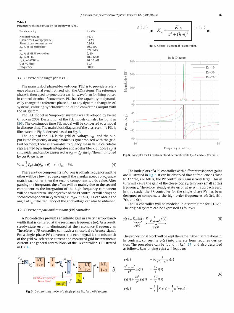
Fig. 5. Bode plot for PR controller for different Kr while Kp = 1 and ω = 377 rad/s.
The Bode plots of a PR controller with different resonance gainsare illustrated in Fig. 5. It can be observed that at frequencies closeto 377 rad/s or 60 Hz, the PR controller’s gain is very large. This inturn will cause the gain of the close-loop system very small at thisfrequency. Therefore, steady-state error at ω will approach zero.In this study, the PR controller for the single-phase PV has beendesigned to compensate the high order frequencies of: 3rd, 5th,7th, and 9th.
The PR controller will be modeled in discrete time for RT-LAB.The original system can be expressed as follows.
y(s) = Kpε(s)︸ ︷︷ ︸y1(s)
+ Krs
s2 + ω2ε(s)︸ ︷︷ ︸
y2(s)
(5)
The proportional block will be kept the same in the discrete domain.In contrast, converting y2(s) into discrete form requires deriva-tion. The procedure can be found in Ref. [27] and also describedas follows. Rearranging y2(s) will leads to:
y2(s) = Krs
s2 + ω2ε(s)
s2 + ω2
s2y2(s) = Kr
sε(s)
y2(s) + ω2
s2y2(s) = Kr
sε(s)
1[
1]
(6)
y2(s) =s
Krε(s) −s
ω2y2(s) .

88 J. Khazaei et al. / Electric Power Systems Research 123 (2015) 85–91
PWM
Db⎧⎪⎨⎪⎩Dccht
amTMiotm
3
ccdoa
3
hphcdc(Ip
⇒
wc
Ft
Dead Band Controller
The combination leads to the increase in PPV. It is possible to haveoscillations in power if the gains of the PI controller are large. Thiscan lead to too much increase in the AC current reference and IPV.At that point, the error signal becomes greater than zero. The AC
Fig. 6. Structure of PR controller.
efining a new variable z, the simplified model of y2(s) is expressedy:
y2(s) = 1s
[Krε(s) − z(s)]
z(s) = 1s
ω2y2(s).
(7)
iscretizing (7) is now limited to an integrator which should behanged from s-domain into discrete time integrator, where 1/sorresponds to Ts
1−z−1 . The block diagram of the proposed controlleras been illustrated in Fig. 6, but due to the space limitations, onlyhe first harmonic has been shown here.
The PR controller aims to control the grid side AC current. Tochieve this objective, the error of the reference PV current andeasured PV current will be used as the input for the PR controller.
he reference current magnitude generated from the output of thePPT block will be synchronized with the grid voltage before send-
ng to the PR controller. The synchronization steps will be carriedut in a single-phase PLL block. The output of the PR controller ishe voltage reference which will be directly sent to the pulse width
odulation (PWM) generation unit.
.3. MPPT for PV systems
The MPPT is the main part in the photovoltaic systems whichan ensure the maximum captured power from the PV array. Itontinuously tunes the system regardless of weather or load con-ition change such as: irradiance change, ambient temperature,r wind which can affect the PV array output. Conventional MPPTlgorithms use dP/dV = 0 to ensure the maximum power harvest.
.3.1. Traditional IC methodThe incremental conductance technique has been implemented
ere which directly focuses on power variations. It means theower slope of the PV is zero at MPP
(dPdV = 0
), positive in the left
and side of MPP and negative in the right hand side. The outputurrent and voltage of the PV panel are used to calculate the con-uctance and incremental conductance. The basic approach is toompare the conductance (I/V) with the incremental conductancedI/dV) and decide when to increase or decrease the PV voltage.n order to reach the maximum power point, the derivative of theower (dP/dV) should be always zero. Considering P = V · I [17]:
dP
dV= d(V · I)
dV= I + V
dI
dV= 0 (8)
dI
dV= − I
V(9)
hich means when the conductance is opposite of the incremental
onductance, the maximum power is guaranteed.The discrete real-time traditional IC MPPT model is shown inig. 7. The conductance will be added to the incremental conduc-ance to generate an error signal. The objective of the PI controller
Fig. 7. The MPPT structure for a single-phase PV in RT-LAB.
is to make the error signal approach zero. For real-time simula-tions of IC, the output of the MPPT is directly sent to the currentcontroller loop to take the advantage of the fast response of thecurrent controller loop. Here the output of the MPPT block will beadded to a constant (PV power divided by the grid voltage RMS) toform the magnitude of reference current value. This current refer-ence will be used in the current control to adjust the grid currentby means of a PR controller. A dead band is used to at dV = 0 condi-tions. If dV becomes zero, the error will be infinity and the proposedMPPT algorithm will not work properly. The traditional dead-bandcontroller in Fig. 7 shows that if dV is zero, a very small value is con-sidered (1e−6) to avoid the error to be infinity. The problem withtraditional dead-band controller is that even the value of dV is setto a small value, large spikes in the output of MPPT will appearwhen dV is oscillating around zero. This is not acceptable for thecontroller.
MPPT mechanism Fig. 8 shows the sample V–I characteristic ofa PV. Suppose the operating point is at Point 1 where the error isgreater than zero. According to the MPPT in Fig. 7, the output ofthe PI unit will increase, which in turn leads to the decrease in theAC current reference. The grid voltage is constant. In addition, thecurrent control response is much faster than MPPT and the currentis synchronized with the grid voltage through PLL. Therefore, thisleads to the reduction in active power at the AC side. Ignore the lossof the switches, the average power at the dc side should be the sameof that at the ac side. Therefore, at the dc side of the converter, if weassume that the dc voltage VPV is kept the same, then the dc currentIPV will have a reduction due to the reduction in the AC currentmagnitude. Reduction in IPV will leads to increase in VPV and PPV.Until the error reaches zero, the PI control will keep adjusting theAC current reference.
Similarly, when the PV system is at Point 3 where the error isless than zero, then the AC current reference will have an increase,which in turn leads to the increase in IPV and the reduction in VPV.
Fig. 8. Error signal description based on I–V characteristic of PV.

J. Khazaei et al. / Electric Power Systems Research 123 (2015) 85–91 89
Fig. 9. Improved IC MPPT for PV systems.
A
B
F
ct
3
sstMb
c
ig. 10. V–I and P–V curves for different irradiance values of Sunpower PV panel.
urrent reference then will see a reduction, so on and so forth tillhe error approaches zero.
.3.2. Modified IC-PI MPPTFor traditional IC-PI MPPT, when dV reaches to zero, the error
ignal will go to infinity and the output of the MPPT will have apike. To solve e problem, the proposed algorithm suggests thathe dV should be removed from the denominator of the error signal.
odified error signal can be considered as: V · dI + I · dV, which can
e viewed as the previous error signal(dIdV + I
V
)multiplied by V · dV.
In this case, dV is no longer in the denominator and it will notause any spikes in MPPT output even when dV is zero. However, the
Fig. 11. Irradiance step change and the MPPT input error.
Fig. 12. The AC current magnitude reference.
error signal should provide the same implication of operation pointposition as the previous error signal. Modification is presented asfollows.
Analysis of the error signal used in traditional IC is presented asfollows.
If error > 0(
dI
dV> − I
V
)⇒
{dV > 0 ⇒ VdI + IdV > 0
dV < 0 ⇒ VdI + −IdV < 0(10)
Eq. (10) shows that if the traditional error is positive, the signof the proposed new error will depend on the sign of dV. If dV ispositive, the defined new error will be positive, same as the tradi-tional error; but if dV is negative, the proposed new error will be
Fig. 13. PV output power and dc current for traditional MPPT.
90 J. Khazaei et al. / Electric Power System
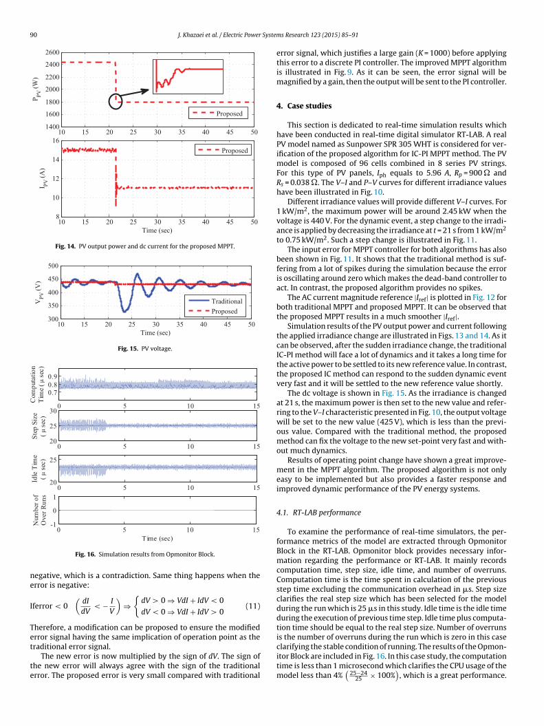
Fig. 14. PV output power and dc current for the proposed MPPT.
Fig. 15. PV voltage.
ne
I
Tet
te
Fig. 16. Simulation results from Opmonitor Block.
egative, which is a contradiction. Same thing happens when therror is negative:
ferror < 0(
dI
dV< − I
V
)⇒
{dV > 0 ⇒ VdI + IdV < 0
dV < 0 ⇒ VdI + IdV > 0(11)
herefore, a modification can be proposed to ensure the modifiedrror signal having the same implication of operation point as the
raditional error signal.The new error is now multiplied by the sign of dV. The sign ofhe new error will always agree with the sign of the traditionalrror. The proposed error is very small compared with traditional
s Research 123 (2015) 85–91
error signal, which justifies a large gain (K = 1000) before applyingthis error to a discrete PI controller. The improved MPPT algorithmis illustrated in Fig. 9. As it can be seen, the error signal will bemagnified by a gain, then the output will be sent to the PI controller.
4. Case studies
This section is dedicated to real-time simulation results whichhave been conducted in real-time digital simulator RT-LAB. A realPV model named as Sunpower SPR 305 WHT is considered for ver-ification of the proposed algorithm for IC-PI MPPT method. The PVmodel is composed of 96 cells combined in 8 series PV strings.For this type of PV panels, Iph equals to 5.96 A, Rp = 900 � andRs = 0.038 �. The V–I and P–V curves for different irradiance valueshave been illustrated in Fig. 10.
Different irradiance values will provide different V–I curves. For1 kW/m2, the maximum power will be around 2.45 kW when thevoltage is 440 V. For the dynamic event, a step change to the irradi-ance is applied by decreasing the irradiance at t = 21 s from 1 kW/m2
to 0.75 kW/m2. Such a step change is illustrated in Fig. 11.The input error for MPPT controller for both algorithms has also
been shown in Fig. 11. It shows that the traditional method is suf-fering from a lot of spikes during the simulation because the erroris oscillating around zero which makes the dead-band controller toact. In contrast, the proposed algorithm provides no spikes.
The AC current magnitude reference |Iref| is plotted in Fig. 12 forboth traditional MPPT and proposed MPPT. It can be observed thatthe proposed MPPT results in a much smoother |Iref|.
Simulation results of the PV output power and current followingthe applied irradiance change are illustrated in Figs. 13 and 14. As itcan be observed, after the sudden irradiance change, the traditionalIC-PI method will face a lot of dynamics and it takes a long time forthe active power to be settled to its new reference value. In contrast,the proposed IC method can respond to the sudden dynamic eventvery fast and it will be settled to the new reference value shortly.
The dc voltage is shown in Fig. 15. As the irradiance is changedat 21 s, the maximum power is then set to the new value and refer-ring to the V–I characteristic presented in Fig. 10, the output voltagewill be set to the new value (425 V), which is less than the previ-ous value. Compared with the traditional method, the proposedmethod can fix the voltage to the new set-point very fast and with-out much dynamics.
Results of operating point change have shown a great improve-ment in the MPPT algorithm. The proposed algorithm is not onlyeasy to be implemented but also provides a faster response andimproved dynamic performance of the PV energy systems.
4.1. RT-LAB performance
To examine the performance of real-time simulators, the per-formance metrics of the model are extracted through OpmonitorBlock in the RT-LAB. Opmonitor block provides necessary infor-mation regarding the performance or RT-LAB. It mainly recordscomputation time, step size, idle time, and number of overruns.Computation time is the time spent in calculation of the previousstep time excluding the communication overhead in �s. Step sizeclarifies the real step size which has been selected for the modelduring the run which is 25 �s in this study. Idle time is the idle timeduring the execution of previous time step. Idle time plus computa-tion time should be equal to the real step size. Number of overrunsis the number of overruns during the run which is zero in this case
clarifying the stable condition of running. The results of the Opmon-itor Block are included in Fig. 16. In this case study, the computationtime is less than 1 microsecond which clarifies the CPU usage of themodel less than 4%(25−24
25 × 100%)
, which is a great performance.

System
Fm
5
eMaadth
A
Ca
R
[
[
[
[
[
[
[
[
[
[
[
[
[
[
[
[[
J. Khazaei et al. / Electric Power
urthermore, there is no overrun detected by the simulator whicheans all the cores are performing in a balanced manner.
. Conclusion
This paper presents real-time digital simulation-based mod-ling of a single-phase single-stage PV grid integration system.odels for the PV panel, PLL, PR current control and MPPT are
ll developed in discrete domain. In addition, an improved MPPTlgorithm is proposed this paper. The proposed MPPT algorithmoes not need dead-band blocks used in traditional IC MPPT con-rol. Simulation case studies demonstrate that the proposed MPPTas a superior performance than the traditional MPPT.
cknowledgements
This research is supported in part by Duke Energy throughommunity Power System Simulation project. The authorscknowledge OPAL-RT for support in RT-LAB setup.
eferences
[1] B. Liu, S. Duan, T. Cai, Photovoltaic dc-building-module-based BIPV system-concept and design considerations, IEEE Trans. IEEE Power Electron. 26 (5)(2011) 1418–1429.
[2] B. Yang, W. Li, Y. Zhao, X. He, Design and analysis of a grid-connectedphotovoltaic power system, IEEE Trans. IEEE Power Electron. 25 (4) (2010)992–1000.
[3] Y.-H. Ji, D.-Y. Jung, J.-G. Kim, J.-H. Kim, T.-W. Lee, C.-Y. Won, A real maximumpower point tracking method for mismatching compensation in PV array underpartially shaded conditions, IEEE Trans. IEEE Power Electron. 26 (4) (2011)1001–1009.
[4] L. Zhang, K. Sun, Y. Xing, L. Feng, H. Ge, A modular grid-connected photovoltaicgeneration system based on dc bus, IEEE Trans. IEEE Power Electron. 26 (2)(2011) 523–531.
[5] J.L. Agorreta, M. Borrega, J. López, L. Marroyo, Modeling and control of-paralleled grid-connected inverters with LCL filter coupled due to gridimpedance in pv plants, IEEE Trans. IEEE Power Electron. 26 (3) (2011)770–785.
[6] M. Park, I.-K. Yu, A novel real-time simulation technique of photovoltaic gen-eration systems using RTDS, IEEE Trans. Energy Convers. 19 (March (1)) (2004)164–169.
[7] O. Craciun, A. Florescu, S. Bacha, I. Munteanu, A. Bratcu, Hardware-in-the-loop testing of PV control systems using RT-LAB simulator, in: 2010 14th
International Power Electronics and Motion Control Conference (EPE/PEMC),September, 2010, S2-1–S2-6.[8] S.B. Kjaer, Evaluation of the “hill climbing” and the “incremental conductance”maximum power point trackers for photovoltaic power systems, IEEE Trans.Energy Convers. 27 (4) (2012) 922–929.
[
s Research 123 (2015) 85–91 91
[9] W. Xiao, W.G. Dunford, A modified adaptive hill climbing MPPT method forphotovoltaic power systems, in: 2004 IEEE 35th Annual Power ElectronicsSpecialists Conference, PESC 2004, vol. 3, IEEE, 2004, pp. 1957–1963.
10] A.K. Abdelsalam, A.M. Massoud, S. Ahmed, P. Enjeti, High-performance adaptiveperturb and observe MPPT technique for photovoltaic-based microgrids, IEEETrans. Power Electron. 26 (4) (2011) 1010–1021.
11] M.A. Elgendy, B. Zahawi, D.J. Atkinson, Assessment of perturb and observe MPPTalgorithm implementation techniques for PV pumping applications, IEEE Trans.Sustain. Energy 3 (1) (2012) 21–33.
12] D. Sera, R. Teodorescu, J. Hantschel, M. Knoll, Optimized maximum power pointtracker for fast changing environmental conditions, in: 2008 IEEE InternationalSymposium on Industrial Electronics, ISIE 2008, IEEE, 2008, pp. 2401–2407.
13] G. Petrone, G. Spagnuolo, R. Teodorescu, M. Veerachary, M. Vitelli, Reliabilityissues in photovoltaic power processing systems, IEEE Trans. Ind. Electron. 55(7) (2008) 2569–2580.
14] A. Safari, S. Mekhilef, Simulation and hardware implementation of incrementalconductance MPPT with direct control method using cuk converter, IEEE Trans.Ind. Electron. 58 (4) (2011) 1154–1161.
15] A. Safari, s. Mekhilef, Incremental conductance MPPT method for PV systems,in: 24th IEEE Canadian Conference on Electrical and Computer Engineering(CCECE 2011), IEEE, 2011, pp. 345–347.
16] A. Pandey, N. Dasgupta, A.K. Mukerjee, Design issues in implementing MPPT forimproved tracking and dynamic performance, in: IECON 2006 – 32nd AnnualConference of IEEE Industrial Electronics, IEEE, 2006, pp. 4387–4391.
17] M. Ciobotaru, R. Teodorescu, F. Blaabjerg, Control of single-stage single-phasePV inverter, in: 2005 European Conference on Power Electronics and Applica-tions, IEEE, 2005, p. 10.
18] E. Koutroulis, F. Blaabjerg, A new technique for tracking the global maximumpower point of PV arrays operating under partial-shading conditions, IEEE J.Photovolt. 2 (2) (2012) 184–190.
19] M.A.G. de Brito, L. Galotto, L.P. Sampaio, G. de Azevedo e Melo, C.A. Canesin,Evaluation of the main mppt techniques for photovoltaic applications, IEEETrans. Ind. Electron. 60 (3) (2013) 1156–1167.
20] B. Liu, F. Duan, F. Liu, P. Xu, Analysis and improvement of maximum power pointtracking algorithm based on incremental conductance method for photovoltaicarray, in: 7th International Conference on Power Electronics and Drive Systems,IEEE, 2007, pp. 637–641.
21] Q. Mei, M. Shan, L. Liu, J.M. Guerrero, A novel improved variable step-sizeincremental-resistance MPPT method for PV systems, IEEE Trans. Ind. Electron.58 (6) (2011) 2427–2434.
22] Z. Yan, L. Fei, Y. Jinjun, D. Shanxu, Study on realizing MPPT by improved incre-mental conductance method with variable step-size, in: 3rd IEEE Conferenceon Industrial Electronics and Applications, ICIEA 2008, IEEE, 2008, pp. 547–550.
23] J.H. Lee, H. Bae, B.H. Cho, Advanced incremental conductance MPPT algorithmwith a variable step size, in: 12th International Conference on Power Electronicsand Motion Control, EPE-PEMC 2006, IEEE, 2006, pp. 603–607.
24] F. Liu, S. Duan, F. Liu, B. Liu, Y. Kang, A variable step size INC MPPT method forPV systems, IEEE Trans. Ind. Electron. 55 (7) (2008) 2622–2628.
25] S.R. Wenham, Applied Photovoltaics, Routledge, 2011.26] H. Pereira, A. Cupertino, C.A. da, S.G. Ribeiro, S. Silva, Influence of PLL in wind
parks harmonic emissions, in: IEEE PES Innovative Smart Grid Technologies
Conference – Latin America (ISGT LA), IEEE, 2013, pp. 1–8.27] R. Teodorescu, F. Blaabjerg, U. Borup, M. Liserre, A new control structure forgrid-connected LCL PV inverters with zero steady-state error and selective har-monic compensation, in: Nineteenth Annual IEEE Applied Power ElectronicsConference and Exposition, APEC’04, vol. 1, IEEE, 2004, pp. 580–586.