electric slide es-20 i es-30 declaration of incorporation ... · es machines must have read and...
TRANSCRIPT

Electric Slide
ES-20 I ES-30
� Declaration of Incorporation
� Module Information
� Installation manual
� Maintenance Instructions
Translation of the original operating manual © Copyright by Afag Automation AG

2 ES20-ES30-BA vers. 1.3 en. 20.11.2017
This operating manual is valid for:
Type Order number
ES-20-050-SL 50425969 ES-20-100-SL 50425970 ES-20-200 ES-20-300 ES-30-050-SL ES-30-100-SL
50425971 50425972 50425973 50425974
ES-30-100 ES-30-200-SL
50425975 50425976
ES-30-200 ES-30-300 ES-30-400 ES-30-500
50425977 50425978 50435979 50425980
Installation and commissioning only by qualified personnel in accordance with the instal-lation manual. Version of this documentation:
ES20-ES30-BA vers. 1.3 en. 20.11.2017
Explanation of symbols and signs :
DANGER
Indicates an immediate threatening danger. Non-compliance with this information can result in death or se-rious personal injuries (invalidity).
WARNING
Indicates a possible dangerous situation. Non-compliance with this information can result in death or se-rious personal injuries (invalidity).
CAUTION
Indicates a possibly dangerous situation. Non-compliance with this information can result in damage to property or light to medium personal injuries.
NOTE
Indicates general notes, useful operator tips and operating recom-mendations which don't affect safety and health of the personnel.
The current serial number is attached here
on delivery of the machine

ES20-ES30-BA vers. 1.3 en. 20.11.2017 3
Table of Contents
1 Declaration of Incorporation for Partly Completed M achinery ................. 6
Machinery Directive: EC Directive 2006/42/EC .............................................. 6 1.1
2 Module Information ................................ ....................................................... 7
2.1 safety instructions ........................................................................................... 7
2.2 Transport, Handling, Storage ......................................................................... 7
2.3 Description ES Electric Slide .......................................................................... 8
2.4 User instructions ............................................................................................. 8
2.5 Observe the notes in the operating manual! ................................................... 9
2.6 Protection against dangerous movements ................................................... 10
2.7 Installation, Connection ................................................................................ 10
2.8 Mounting Instructions ................................................................................... 12
2.9 Centering Sleeves ........................................................................................ 13
2.10 Tightening Torques for Bolts ........................................................................ 14
2.11 Operating Conditions .................................................................................... 14
2.12 Installation of the ES Electric Slides in a System ......................................... 15
2.13 Electric Slide ES-20 ...................................................................................... 16
2.14 Electric Slide ES-30 ...................................................................................... 17
2.15 Preferred combinations ES20 ....................................................................... 18
2.16 Preferred combinations ES30 ....................................................................... 19
2.17 Programming ES Electric Slides ................................................................... 20
3. Installation Manual ............................... ....................................................... 21
3.1 Manufacturer's address: ............................................................................... 21
3.2 Includes in the delivery ................................................................................. 22
3.3 Intended use ................................................................................................. 22
3.4 Warranty ....................................................................................................... 23
3.5 Safety ........................................................................................................... 23
3.6 Dimensional Drawing ES20 .......................................................................... 24
3.7 Technical Data ES20 .................................................................................... 25
3.8 Module stresses ES20 .................................................................................. 26
3.9 Dimensional Drawing ES30 .......................................................................... 27
3.10 Technical Data ES-30 ................................................................................... 28
3.11 Module stresses ES30 .................................................................................. 29
4 ES20-ES30-BA vers. 1.3 en. 20.11.2017
3.12 Base enclosure to the mounting system ....................................................... 30
3.13 Commissioning, Operation, Training ............................................................ 30
3.14 Preparation for commissioning ..................................................................... 31
3.15 Commissioning ............................................................................................. 32
3.16 Set conversion .............................................................................................. 33
3.17 Normal operation .......................................................................................... 34
3.18 Set Speeds of the Electric Axes ................................................................... 35
4. Maintenance ....................................... ......................................................... 36
4.1 After commissioning ..................................................................................... 36
4.2 Every 3 months ............................................................................................ 36
4.3 Repairs ......................................................................................................... 37
5. Accessories ....................................... .......................................................... 38
5.1 Description MagSpring ................................................................................. 38
5.2 Overview MagSpring ES20 .......................................................................... 39
5.3 Technical data MagSpring ES20 11N-22N .................................................. 40
5.4 Technical data MagSpring ES20 40N-60N .................................................. 42
5.5 Overview MagSpring ES30 .......................................................................... 44
5.6 Technical data MagSpring ES30 11N-22N .................................................. 45
5.7 Technical data MagSpring ES30 40N-60N .................................................. 47
5.8 MagSpring .................................................................................................... 49
5.9 Mounting MagSpring laterally ....................................................................... 50
5.10 Mounting MagSpring in front ........................................................................ 51
5.11 Compensation spring .................................................................................... 52
5.12 Attachment compensation spring ................................................................. 53
5.13 External position measuring system for ES20 and ES30 ............................. 54
5.14 Mass for external position measuring system for ES20 ................................ 55
5.15 Mass for external position measuring system for ES30 ................................ 56
5.16 Setting of the external path measuring system ............................................. 57
5.17 Overview of servo controllers ....................................................................... 58
5.18 Technical data of the servo controller C11xx ................................................ 59
5.19 Dimension drawing of the servo controller C11xx ........................................ 59
5.20 Technical data of the servo controller C12xx ................................................ 60
5.21 Dimension drawing of the servo controller C12xx ........................................ 60

ES20-ES30-BA vers. 1.3 en. 20.11.2017 5
5.22 Technical data of the servo controller E11xx ................................................ 61
5.23 Dimension drawing of the servo controller E11xx ......................................... 61
5.24 Technical data of the servo controller E12xx ................................................ 62
5.25 Dimension drawing of the servo controller E12xx ......................................... 62
5.26 Overview servo controller, cable, connector ................................................. 63
5.27 Accessories servo controller C1xxx .............................................................. 64
5.28 Technical data and dimensional drawings for transformers and power supplies 65
5.29 Technical data and dimensional drawings for Cable .................................... 68
5.30 Supports for ES Modules .............................................................................. 71
6. Disposal .......................................... ............................................................. 72

6 ES20-ES30-BA vers. 1.3 en. 20.11.2017
1 Declaration of Incorporation for Partly Completed Machinery
Machinery Directive: EC Directive 2006/42/EC 1.1
Standard: EN ISO 12100:2010 (German version)
The manufacturer: Afag Automation AG, Fiechtenstrasse 32, CH-4950 Hut twil, Switzerland hereby declares that the following products: ES-20-050-SL ES-30-050-SL ES-30-200 ES-20-100-SL ES-30-100-SL ES-30-300 ES-20-200 ES-30-100 ES-30-400 ES-20-300 ES-30-200-SL ES-30-500
comply with the applicable EC Directives: EC Low-Voltage Directive 2014/35/EU EMC Directive 2014/30/EU Applied harmonised standards:: EN 349; EN 60204-1:2006
- Safety of machinery - General principles for design - Risk assessment and risk reduction
- In response to a duly substantiated request, these special technical documents will be submitted to the competent national authorities as printed documents or in electronic form (pdf).
Directive: Applied and satisfied fundamental requir ements:
1.1; 1.1.1; 1.1.2; 1.1.3, 1.1.5, 1.3.2, 1.3.4 and 1.5.1
The person or company installing this partly completed machinery or combining it with other machinery must carry out a risk assessment for the resulting machinery that satis-fies the requirements of the EC Directive: 2006/42/EC . Standard: EN ISO 12100:2010 (German version) Authorised representative:
Responsibility for the compilation of the technically relevant documents lies with:
Niklaus Röthlisberger, Product Manager, Afag Automation AG, CH-4950 Huttwil
Place/date: Huttwil, 20.11.2017
Siegfried Egli
Managing Director Afag Automation AG
Niklaus Röthlisberger
Product Manager Afag Automation AG

ES20-ES30-BA vers. 1.3 en. 20.11.2017 7
2 Module Information
2.1 safety instructions
DANGER
The strong magnetic fields may interfere with and i mpair the function of electronic devices, such as pacemakers, even when the module is switched off. Persons with a pacemaker must keep a safety distanc e of at least 50 cm.
Modifications to the linear modules ES that are not described in this Montage Instruction or have not been approved in writing by the company Afag Automation AG are not per-mitted. In case of improper changes or assembly, installation, operation, maintenance or repairs, Afag Automation AG rejects all liability.
2.2 Transport, Handling, Storage
For transport and storage, the following must be met:
Temperature storage: 0-50°C
Air humidity: <90%, non condensing
CAUTION
The ES linear modules are packed. In case of improp er handling the module may drop out when it is unpacked and cau se inju-ries to limbs.
The transport takes place in the transport packaging of Afag Automation AG. If there is no packaging of Afag Automation AG are used, they must be the axis shock and dust packed.
The ES linear modules are in the transport package dry storage
The ES linear modules have a weight from 0.9 to 7.0 kg (depending on the stroke length).
NOTE
Please note: A technical safety information sheet is enclosed with each module. This information sheet must be read by every person who operates the module.

8 ES20-ES30-BA vers. 1.3 en. 20.11.2017
2.3 Description ES Electric Slide
The ES Electric Slides are used in automation systems and are intended exclusively for the movement of workpieces. The ES Electric Slides are intended exclusively for operation with original LinMot compo-nents (controllers, cables, etc.). Use for any other purpose does not constitute an intend-ed use. The intended use also includes compliance with the prescribed installation and removal instructions, the service and maintenance conditions and observance of the specifica-tions in the data sheets.
Notice the magnetic fields!
DANGER
The strong magnetic fields may interfere with and i mpair the function of electronic devices, such as pacemakers, even when the module is switched off. Persons with a pacemaker must keep a safety distanc e of at least 50 cm.
2.4 User instructions
The ES Electric Slides are built to the state-of-the-art and the generally accepted safety regulations and may only be used
� For the intended purpose
� In an operationally safe condition

ES20-ES30-BA vers. 1.3 en. 20.11.2017 9
ES Electric Slides are available in the following versions:
Type Stroke Number
Guide carriage Order number
ES-20-050-SL 50 mm 1 50425969 ES-20-100-SL 100 mm 1 50425970 ES-20-200 200 mm 2 50425971 ES-20-300 300 mm 2 50425972 ES-30-050-SL 50 mm 1 50425973 ES-30-100-SL 100 mm 1 50425974 ES-30-100 100 mm 2 50425975 ES-30-200-SL 200 mm 1 50425976 ES-30-200 200 mm 2 50425977 ES-30-300 300 mm 2 50425978 ES-30-400 400 mm 2 50425979 ES-30-500 500 mm 2 50425980 Installation and commissioning only by qualified personnel in accordance with the instal-lation manual.
2.5 Observe the notes in the operating manual!
A precondition for the safe handling and problem-free operation of the ES Electric Slides is the knowledge of the fundamental safety regulations.
All persons involved in the installation, commissioning, maintenance and operation of the ES machines must have read and understood the complete operating manual, in particu-lar the chapter "Safety instructions".
Furthermore, the rules and regulations on accident prevention applicable at the place of installation/operation must also be observed. Improper use may result in dangers for the life and limb of the operator or third parties and in impairments to the machine or other assets.
In the event of faults that could impair safety, the machine must be switched off immedi-ately and secured to prevent restarting. The fault must then be remedied.
All work on the machines must be carried out with the machines depressurised and dis-connected from the electrical power supply.
For the operation of the machines, the user must provide safety hoods, safety doors or other safety precautions conforming to the normal safety guidelines and safety standards which prevent people from entering or remaining in the working area of the machines during operation. The machines may only be put into operation when the guards are se-curely closed.

10 ES20-ES30-BA vers. 1.3 en. 20.11.2017
2.6 Protection against dangerous movements
Dangerous movements can occur if drives are actuated incorrectly. The drive compo-nents are monitored so that a malfunction can be effectively ruled out. For reasons of personal safety, the risk of injury and the risk of material damage, however, this must not be relied on completely. Faulty drive movements must be expected until installed moni-toring devices become active.
2.7 Installation, Connection
WARNING
The ES Electric Slides are set in motion by the ele ctric control system. If the ES Electric Slides cannot move freel y, there is a risk of injury and crushing in conjunction with att achments.
If attachments on the ES modules can pose a hazard in con-junction with the moving slides, a correspondingly safe opera-tion must be ensured.
Measures must be taken to ensure that the operator cannot en-ter the working area of the ES Electric Slides duri ng normal op-eration.
The chosen solution is dependent on the safety conc ept of the plant and the installed modules.
WARNING
Due to the decentralised control, the operator of t he ES Electric Slide is not necessarily alongside the product and can therefore endanger other persons in other areas.
During manipulation of the ES Electric Slide, the c ontroller ena-ble must be deactivated and reactivated only after completion of the work.

ES20-ES30-BA vers. 1.3 en. 20.11.2017 11
CAUTION
The ES Electric Slide is a partially completed mach ine.
For safe operation, the ES Electric Slide must be i ntegrated into the safety concept of the plant in which it is inst alled.
Measures must be taken to ensure that the operating personnel cannot enter the working area of the ES Electric Sl ides during operation.
Depending on the version and the installation, ther e is an addi-tional safety risk, e.g. of pinching fingers!
The ES Electric Slide may only be used for its inte nded pur-pose.
Measures must be taken to ensure that the operator cannot en-ter the working area of the ES Electric Slide durin g normal op-eration. This can be achieved by suitable protectiv e measures such as enclosures, light barriers or de-energisati on of the drive.

12 ES20-ES30-BA vers. 1.3 en. 20.11.2017
2.8 Mounting Instructions
The ES Electric Slides (up to sizes ES-30-400 and ES-30-500) can be installed in any position, the mounting holes (M4 on ES-20) and (M6 on ES-30) are located in the base element and in the slide. Use the centering sleeves included in the scope of supply. The ES-30-400 and ES-30-500 may only be installed horizontally as they have no load com-pensation for vertical installation.
Mounting holes ES-20 (M4) Hole pitch 30 x 30 mm
In slide ES-30 (M6) Hole pitch 48 x 48 mm
Mounting holes ES-20 (dia. 4.1) Hole pitch 30 x 30 mm
In base element ES-30 (dia. 6.3) Hole pitch 48 x 48 mm

ES20-ES30-BA vers. 1.3 en. 20.11.2017 13
2.9 Centering Sleeves
ES-20 Base element Slide Hole pitch 30x30 mm 30x30 mm Bore and mounting thread dia. 4.1 mm M4 Centering sleeves (H7) 11016850 dia. 7 mm dia. 7 mm
ES-30 Base element Slide Hole pitch 48x48 mm 48x48 mm Bore and mounting thread dia. 6.3 mm M6 Centering sleeves (H7) 11004942 dia. 9 mm dia. 9 mm
Use the centering sleeves supplied for positioning. Insert these into two diagonally op-posed bores of the installation grid.

14 ES20-ES30-BA vers. 1.3 en. 20.11.2017
2.10 Tightening Torques for Bolts
Bolts meeting at least the following specification must be used for installation:
Standard: VDI 2230 Strength: Class 8.8 Surface: Blue galvanised, oiled or greased Thread Tightening torques
M3 1.1 … 1.4 Nm
M4 2.6 … 3.3 Nm
M5 5.2 … 6.5 Nm
M6 9.0 ... 11.3 Nm
M8 21.6 … 27.3 Nm
2.11 Operating Conditions
The series of the ES Electric Slides is intended for jerk-free linear movement of firmly installed loads in non-explosive atmospheres and under the ambient and operating conditions defined for these modules. The ES Electric Slides can be installed horizontally or vertically. With vertical installation, a weight compensation must be installed using a MagSpring which prevents the ES Electric Slide from extending when the electric power is switched off.
NOTE
This installation manual must be read carefully before any work on or with the ES Electric Slide. The ES Electric Slide may only be used for its intended purpose.

ES20-ES30-BA vers. 1.3 en. 20.11.2017 15
2.12 Installation of the ES Electric Slides in a Sy stem
CAUTION
The ES Electric Slides may only be installed in a s ystem when the control system is switched off and secured. The ES Electric Slides may only be installed by qualified technical personnel.
Connect and disconnect cables only when the control system is switched off!
NOTE
The plant installer bears sole responsibility for the installation of the ES Electric Slides!

16 ES20-ES30-BA vers. 1.3 en. 20.11.2017
2.13 Electric Slide ES-20
The ES Electric Slides are electric modules with a contact-free, wear-free direct drive (linear motor).
CAUTION
The tape of the external measuring system contains magnetic infor-mation. A sufficient distance to other magnets must be maintained at all times.
Motor plug rotatable
Mounting of the periphery: - 6x M4 with dia. 7 H7 centering Hole pitch 30 x 30 mm - 4x M3 with dia. 5 H7 centering Hole pitch 20 x 20 mm
Grease nipple
External measuring system (op-tional) Installation on both sides possi-ble
MagSpring (optional) With vertical installation Installation on three sides pos-sible
Mounting of the module (base element): - dia. 4.1 with dia. 7 H7 centering Hole pitch 30 x 30
mm
Mounting of the module (slide): - M4 with dia. 7 H7 centering - Hole pitch 30 x 30 mm

ES20-ES30-BA vers. 1.3 en. 20.11.2017 17
2.14 Electric Slide ES-30
The ES Electric Slides are electric modules with a contact-free, wear-free direct drive (linear motor).
CAUTION
The tape of the external measuring system contains magnetic infor-mation. A sufficient distance to other magnets must be maintained at all times.
MagSpring (optional) With vertical installation Installation on three sides possible
Motor plug rotatable
Mounting of the periphery: - 4x M6 with dia. 9 H7 centering Hole pitch 48 x 48 mm - 6x M4 with dia. 7 H7 centering Hole pitch 30 x 30 mm
Grease nipple
External measuring system (op-tional) Installation on both sides possi-ble
Mounting of the module (base element): - dia. 6.3 with dia. 9 H7 centering Hole pitch 48 x 48
mm
Mounting of the module (slide): - M6 with dia. 9 H7 centering - Hole pitch 48 x 48 mm

18 ES20-ES30-BA vers. 1.3 en. 20.11.2017
2.15 Preferred combinations ES20

ES20-ES30-BA vers. 1.3 en. 20.11.2017 19
2.16 Preferred combinations ES30

20 ES20-ES30-BA vers. 1.3 en. 20.11.2017
2.17 Programming ES Electric Slides
CAUTION
The ES linear modules should be started up in set-u p or jog mode. A wrong programming may trigger uncontrolled move-ments of the ES linear modules. Fast or unintention al move-ments of the module can result in personal injury a nd damage to property.
The programming depends on the control system used. Observe the respective manuals of the control system supplier.
WARNING
If wrong basi c data is input at the PLC the ES linear module may move unhindered against the stopper leading to injury to persons by parts flying around. In case of a failure of the displacement encoder or a defective limit switch cable the ES linear module may execute unex-pected movements. Persons working on the system may be in-jured.
WARNING
It is the responsibility of the system manufacturer to ensure that the system is protected with a safety fence so that persons are not injured during operation.

ES20-ES30-BA vers. 1.3 en. 20.11.2017 21
3. Installation Manual
3.1 Manufacturer's address:
Afag Automation AG
Fiechtenstrasse 32
CH-4950 Huttwil
Sales Handling:
Tel. +41 62 959 87 02
www.afag.com
This installation manual is intended for: Electric Slide ES Types ES-20-050-SL ES-20-100-SL ES-20-200 ES-20-300 ES-30-050 SL ES-30-100 SL ES-30-100 ES-30-200 SL ES-30-200 ES-30-300 ES-30-400 ES-30-500 This is partly completed machinery
The person or company installing this partly completed machinery or combining it with other machinery must carry out a risk assessment for the resulting machinery that satis-fies the requirements of the EC Directive: 2006/42/EC . Standard: EN ISO 12100:2010 (German version) For the installation of the partly completed machinery the following conditions must be satisfied so that it can be assembled together with other parts to form a complete machine correctly and without endangering the health and safe-ty of persons:
� Observe the safety precautions in the risk assessment � Read, understand and observe the whole operating manual � Installation may only be carried out by qualified technical personnel.
Authorised representative:
Responsibility for the compilation of the technically relevant documents lies with: Niklaus Röthlisberger, Product Manager HT, Afag Automation, CH-4950 Huttwil.
22 ES20-ES30-BA vers. 1.3 en. 20.11.2017
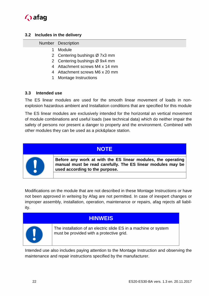
3.2 Includes in the delivery
Number Description
1 2 2 4
Module Centering bushings Ø 7x3 mm Centering bushings Ø 9x4 mm Attachment screws M4 x 14 mm
4 1
Attachment screws M6 x 20 mm Montage Instructions
3.3 Intended use
The ES linear modules are used for the smooth linear movement of loads in non-explosion hazardous ambient and Installation conditions that are specified for this module
The ES linear modules are exclusively intended for the horizontal an vertical movement of module combinations and useful loads (see technical data) which do neither impair the safety of persons nor present a danger to property and the environment. Combined with other modules they can be used as a pick&place station.
NOTE
Before any work at with the ES linear modules, the operating manual must be read carefully. The ES linear module s may be used according to the purpose.
Modifications on the module that are not described in these Montage Instructions or have not been approved in writeing by Afag are not permitted. In case of inexpert changes or improper assembly, installation, operation, maintenance or repairs, afag rejects all liabil-ity.
HINWEIS
The installation of an electric slide ES in a machine or system must be provided with a protective grid.
Intended use also includes paying attention to the Montage Instruction and observing the maintenance and repair instructions specified by the manufacturer.

ES20-ES30-BA vers. 1.3 en. 20.11.2017 23
CAUTION
The ES linear module may only be operated and servi ced by correspondingly trained personnel who have also pro found knowledge of the dangers.
The applicable regulations for prevention of accide nts and the other generally accepted safety-relevant and occupa tional safe-ty and health regulations are to be followed.
3.4 Warranty
3.5 Safety
This Montage Instructions should be read carefully before carrying out any activity on or with the module. The module may only be deployed in accordance with the intended use. Modifications on the module that are not described in this Montage Instructions or have not been approved in writing by Afag are not permitted. In case of improper changes or assembly, installation, operation, maintenance or repairs, Afag AG rejects all liability.
CAUTION
Connection of a control system and operation of the ES linear module can lead to unpredictable movements which ma y result in personal injury or damage to property.
The term of the warranty on Afag handling components and systems is: • 24 months following commissioning, but a maximum of 27 months following delivery. • Wear parts (e.g. shock absorbers) are not covered by the warranty. *
The warranty covers the replacement or repair of defective Afag parts. No further claims will be accepted.
The warranty will be voided in event of the following: • Use for other than the intended purpose • Failure to observe the notes on installation, commissioning, operation and maintenance in the operat-
ing manual • Improper installation, commissioning, operation and maintenance • Independent repairs and constructional changes without prior instruction by Afag Automation AG • Removal of the serial number on the product • Using the module without shock absorbers, or with defective shock absorbers • Inadequate monitoring of wear parts
*A customer has the right to a defect-free product. This is also applicable for accessories and wear parts, if they are defective. However, wear does not fall within the scope of the warranty.

24 ES20-ES30-BA vers. 1.3 en. 20.11.2017
3.6 Dimensional Drawing ES20

ES20-ES30-BA vers. 1.3 en. 20.11.2017 25
3.7 Technical Data ES20

26 ES20-ES30-BA vers. 1.3 en. 20.11.2017
3.8 Module stresses ES20

ES20-ES30-BA vers. 1.3 en. 20.11.2017 27
3.9 Dimensional Drawing ES30

28 ES20-ES30-BA vers. 1.3 en. 20.11.2017
3.10 Technical Data ES-30

ES20-ES30-BA vers. 1.3 en. 20.11.2017 29
3.11 Module stresses ES30

30 ES20-ES30-BA vers. 1.3 en. 20.11.2017
3.12 Base enclosure to the mounting system
NOTE
The Installation of a ES-linear module in an assembly system, the System with a base enclosure or protective device fitted be locked door with safety circuit.
3.13 Commissioning, Operation, Training
CAUTION
Adjustments and modifications may only be achieved by quali-fied technical staff, familiar with the system
Taken during manipulation of the linear module has secured the control release and be turned on after completion of the work again.
WARNING
The ES linear module may execute unpredictable movements when the control system is switched on which can ca use seri-ous personal injuries or damage to property. Make sure that the control system is switched off a nd secured against being switched on again when working on the module.
Only disconnect or connect cables when the control system is switched off.
WARNING
Due to the decentral controller the operator of the ES linear module needs not to be near the product so that thi rd persons might be endangered by the module operation.
Always switch off the controller and protect it fro m being switched on again unintentionally when you work on the LE lin-ear module. The signals of the control system may c ause unin-tentional movements of the module which may lead to personal injuries.
Observe the Montage Instructions of the control system used.

ES20-ES30-BA vers. 1.3 en. 20.11.2017 31
3.14 Preparation for commissioning
The ES linear module is designed for being operated with the LinMot servo controller.
Operation of the LinMot servo controller is described in the particular operating instruc-tions.
The ES20 linear module are connected to the corresponding servo controller with the M16 or M20 motor cable.
The ES30 linear module is connected to the corresponding servo controller with the M17 or M22 motor cable.
First connect the control system to a PC on which the operating software was installed and carry out the test run. The use of the operating software is described in the Installa-tion Instructions of the program.
If the ES linear module is delivered together with an LinMot servo controller the operating parameters have already been stored on the controller. The ES linear module can be started immediately.

32 ES20-ES30-BA vers. 1.3 en. 20.11.2017
3.15 Commissioning
WARNING
The commissioning of the ES module should be set-up or Step operation done. Incorrect programming can unco ntrolled movement of the axle system trigger. Fast or unintentional movements of the system can cause inj ury or death, property damage, and you cause. Ensure that off when working on the control axle sy stem and is switched on again.
� Carry out the first start-up slowly and step by step.
� Note the permissible technical data (see catalogue) regarding:
- load capacity - motion frequency - moment load
WARNING
Limbs may be crushed by moving components.
� Make sure that there are no persons or tools within the operating range of the mod-ule.
� Carry out a test run.
� Connect the cables to the LE linear module and the control system.
At first with slow speed, then under the effective montage conditions.
Incorrect operation of the system
CAUTION
During set-up work the LE linear module may start d ue to wrong operation and cause injuries to persons working on the system.
ES20-ES30-BA vers. 1.3 en. 20.11.2017 33
WARNING
It is the responsibility of the system manufacturer that persons perform their work properly when adjusting the ES l inear mod-ule in an open system so that an uncontrolled start -up of the axis is prevented.
3.16 Set conversion
WARNING
The ES linear modules are moved by the electric control. If the ES linear module cannot move freely there is danger of injuries and bruises near the add-ons. If add-ons at the ES linear module could cause dang er in con-nection with the moving slide a safe operation must be ensured.
WARNING
Due to the decentral controller the operator of the ES linear module needs not to be near the product so that thi rd persons might be endangered by the module operation. Always switch off the controller and protect it fro m being switched on again unintentionally when you work on the ES lin-ear module. The signals of the control system may c ause unin-tentional movements of the module which may lead to personal injuries.
34 ES20-ES30-BA vers. 1.3 en. 20.11.2017
3.17 Normal operation
WARNING
The ES linear modules are moved by the electric control. If the ES linear module cannot move freely there is danger of injuries and bruises near the add-ons. If add-ons at the ES linear module could cause dang er in con-nection with the moving slide a safe operation must be ensured.
WARNING
Due to the decentral controller the operator of the ES linear module needs not to be near the product so that thi rd persons might be endangered by the module operation. Do not reach into the system during standard operat ion.
NOTE
Settings and modifications may be done by qualified personnel which is trained to be executed.

ES20-ES30-BA vers. 1.3 en. 20.11.2017 35
3.18 Set Speeds of the Electric Axes
The speeds of the electric axes are generally set by the higher-ranking controller.
Example programs are available for a large number of common controllers which allow the maximum speed, acceleration and target position to be set.
These travel profiles are stored in the controller when using the B1100-PP or E1100-GP controller with EasyStep firmware.
CAUTION
An excessively high speed or acceleration can cause damage to the device of the periphery.
The following tables are intended as references for the parameters (speed, acceleration, deceleration).
Please note that you do not have to adapt the standard parameters for your application. They are heavily dependent on the load mass and the mechanical configuration.

36 ES20-ES30-BA vers. 1.3 en. 20.11.2017
4. Maintenance
4.1 After commissioning
• Check bolts for tightness
• Clean the guides using a slightly oily cloth
• Check the setting of the damping
• Check adjustment of the ES20 and ES30 guide
4.2 Every 3 months
ES20 and ES30
• Clean the guides using a slightly oil cloth
• Check adjustment of the ES20 and ES30 guide and correct, if necessary
• Observe the instructions for the linear motor
• Fully retract the axis
• Remove the cap of the grease nipple
• Pump in grease using a grease gun (Recommended: Klübersynth UH1 14-31 or grease with comparable properties)
Lubricants meeting the following minimum requirements and specifications may be used:
Lubricant DIN designation DIN number Remarks
Lubricating grease KP 2 – K 51502 or 51825 Lithium saponified grease
Lubricating oil CLP32 – 100 51517 Part 3 ISO VG 32-68
Linear motors: • Linear motor axes with underdimensioned (diameter 19 or 27) rotor: - Clean rotor • Linear motor axes with wiper: - Clean rotor - Fill a grease gun with Klübersynth UH1 14-31 grease and pump in grease via the grease nipple of the axis

ES20-ES30-BA vers. 1.3 en. 20.11.2017 37
MagSpring:
• Clean rotor
• Coat the rotor with Klübersynth UH1 14-31 grease
CAUTION
Only the specified grease may be used for lubricati on of the lin-ear motor axes and the MagSpring.
CAUTION
If the device makes abnormal movements during norma l opera-tion, e.g. hard banging, the causes should be immed iately rem-edied.
The service and maintenance intervals must be observed. The intervals are based on a normal environment. The approval of Afag Automation AG must be obtained in advance if the devices are to be operated in an environment with abrasive dusts or with corrosive or aggressive vapours, gases or liquids.
4.3 Repairs
Repairs other than those described below may only be carried out by Afag Automation AG.
If you carry out the repair yourself, approval must be obtained in advance from Afag Au-tomation AG.
CAUTION
Repairs may only be carried out by qualified person nel.

38 ES20-ES30-BA vers. 1.3 en. 20.11.2017
5. Accessories
5.1 Description MagSpring
The MagSpring is a passive component with a constant force over a certain stroke range based on permanent magnets.
As a result, the load mass is compensated for vertically installed axes (counterbalance in vertical mounting position). The dropping of the periphery or the workpiece is prevented, when the electric slide is de-energized.
The MagSpring is offered with a holder, suitable for the ES electric slides ES20 and ES30. This can be mounted laterally, left, right, or in front of the axle.
Advantages:
- Constant force over the entire stroke range
- overstretching of the spring is impossible
- Energy-efficient weight compensation
Slider
Stator
Bracket
Bracket
ES20-ES30-BA vers. 1.3 en. 20.11.2017 39
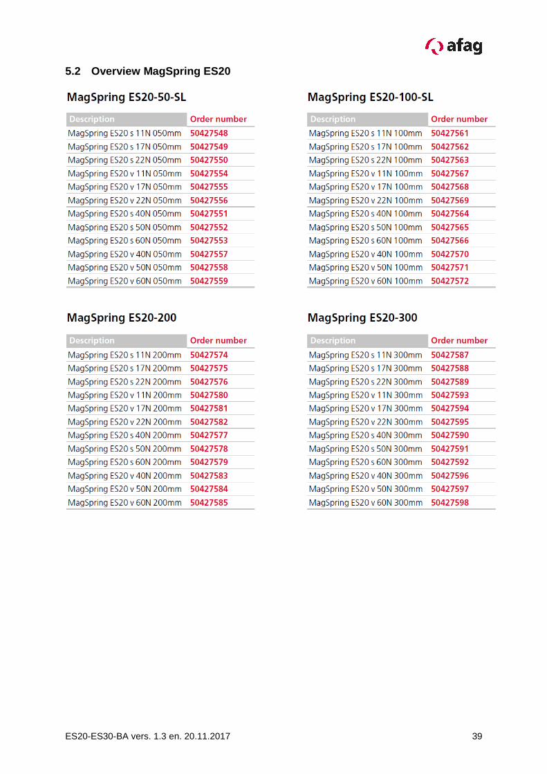
5.2 Overview MagSpring ES20

40 ES20-ES30-BA vers. 1.3 en. 20.11.2017
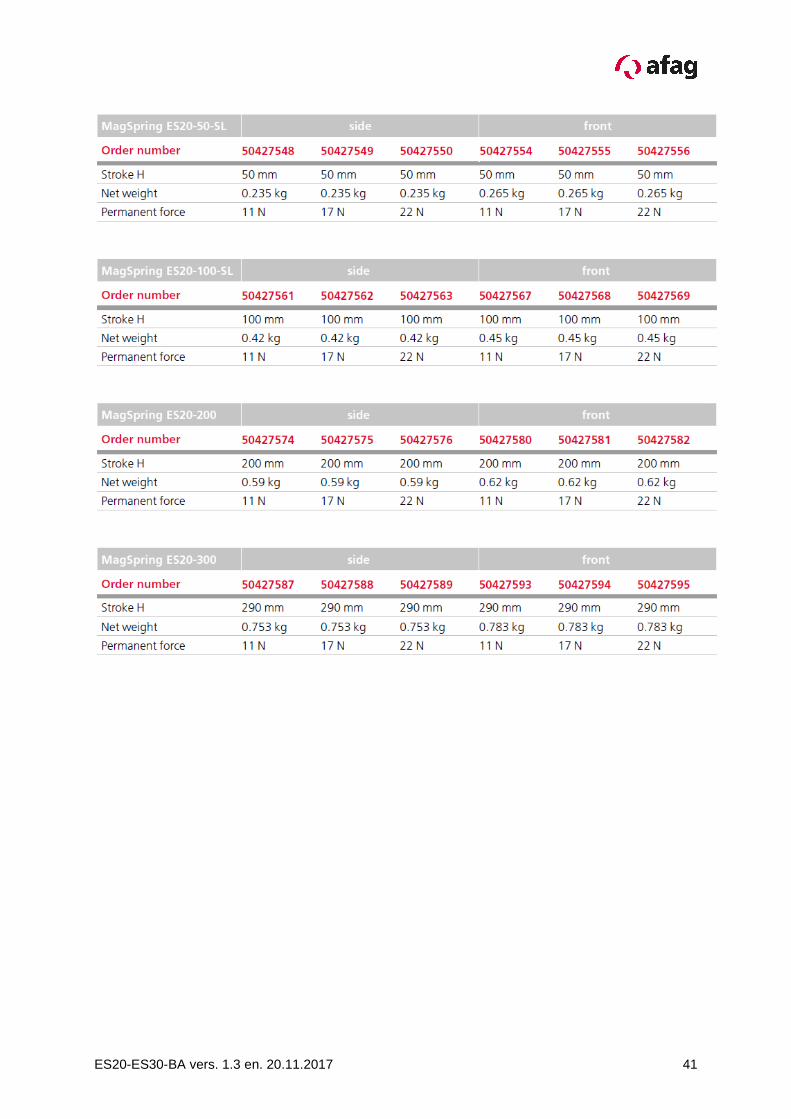
5.3 Technical data MagSpring ES20 11N-22N
ES20-ES30-BA vers. 1.3 en. 20.11.2017 41

42 ES20-ES30-BA vers. 1.3 en. 20.11.2017
5.4 Technical data MagSpring ES20 40N-60N

ES20-ES30-BA vers. 1.3 en. 20.11.2017 43
44 ES20-ES30-BA vers. 1.3 en. 20.11.2017
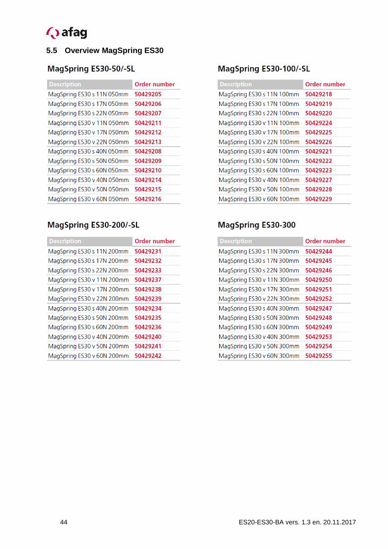
5.5 Overview MagSpring ES30

ES20-ES30-BA vers. 1.3 en. 20.11.2017 45
5.6 Technical data MagSpring ES30 11N-22N

46 ES20-ES30-BA vers. 1.3 en. 20.11.2017

ES20-ES30-BA vers. 1.3 en. 20.11.2017 47
5.7 Technical data MagSpring ES30 40N-60N

48 ES20-ES30-BA vers. 1.3 en. 20.11.2017

ES20-ES30-BA vers. 1.3 en. 20.11.2017 49
5.8 MagSpring
Due to the stroke-independent force generation, the MagSprings are used for the com-pensation of weight forces in vertical drive configurations.
The following installation positions apply for the installation of the MagSpring: The thread on the stator and the end of the rotor with four flats are facing downwards. In the normal installation position, dimension SP=35, adjusted by clamping the Mag-Spring stator with fully retracted slide. This measure (SP=35) is the same for all Mag-Springs.
Normal mounting position Module
Functionality
The mode of operation is based on the attraction force of permanent magnets.
Correspondingly, no power supply (electricity, com-pressed air, etc.) is necessary so that safety relevant ap-plications are also possible.
Due to the special design of the flux-carrying compo-nents, as wel as of the magnets, the highly non linear relationships between force and displacement of magnet arrangements are converted into a constant force profile.
Depending on the strength class of the MagSpring, the permanent magnets are located either in the stator, in the rotor or in both components.
The rotor is supported by an integrated sliding guide so that the MagSpring can be used in a similar manner to gas pressured springs.
In case of vertical installation, linear motors and other direct drives must constantly apply a constant force in order to counteract the weight force. With a MagSpring installed parallel to the linear motor, the weight force can be passively compensated. The linear motor is used only for the actual positioning operation or the application of the dynamic forces and can be correspondingly be re-duced. 2.7 Installation, Connection

50 ES20-ES30-BA vers. 1.3 en. 20.11.2017
5.9 Mounting MagSpring laterally
The MagSpring for the lateral attachment is supplie d as a set and consists the fol-lowing components:
Pos. Description
A MagSpring Stator und rotor
B Bracket
C 6kt-Nut
D Compensating element
E Adapter
F Mounting parts
The order numbers of the MagSpring can be found under Accessories MagSpring.

ES20-ES30-BA vers. 1.3 en. 20.11.2017 51
5.10 Mounting MagSpring in front
The MagSpring for the front attachment is supplied as a set and consists the fol-lowing components:
Pos. Beschreibung
A MagSpring Stator und rotor
B Bracket
C 6kt-Nut
D Compensating element
E Adapter
F Mounting parts
The order numbers of the MagSpring can be found under Accessories MagSpring.

52 ES20-ES30-BA vers. 1.3 en. 20.11.2017
5.11 Compensation spring

ES20-ES30-BA vers. 1.3 en. 20.11.2017 53
5.12 Attachment compensation spring
As a cost-efficient alternative to a MagSpring, a compensating spring (mechanical spring) can be used. This compensating spring may only be used with the ES20-50-SL, with stroke length 50 mm and small mass. It should be noted, that the compensating spring has a non-constant force. The compensating spring is supplied as a set and co nsists of the following com-ponents:
Pos. Beschreibung
A Top clamp
B Cylinder pin
C Tension spring
D Spring cover
E Holder spring cover
F Clamp at the bottom
G Mounting parts

54 ES20-ES30-BA vers. 1.3 en. 20.11.2017
5.13 External position measuring system for ES20 an d ES30
The contactless position measuring system on a magnetic basis with integrated evalua-tion electronics is used everywhere, where you cannot safely reference the axes. In addi-tion, a high positional accuracy, a high accuracy are achieved and quiet driving behavior. The system consists a sensor and a tape on which magnetic information are stored. Both components are fixed to the module. With the internal measuring system of the motor, a repeatability of ± 0.05 mm and a devi-ation of the absolute accuracy between 0.1% and 0.4% (depending on the drive unit). Is this not enough, we recommend an external measuring system. Advantages: � Referencing not necessary
� High repeatability and absolute accuracy
� Dynamic and quiet driving
� Minimize control noise

ES20-ES30-BA vers. 1.3 en. 20.11.2017 55
5.14 Mass for e xternal position measuring system for ES20

56 ES20-ES30-BA vers. 1.3 en. 20.11.2017
5.15 Mass for external position measuring system fo r ES30

ES20-ES30-BA vers. 1.3 en. 20.11.2017 57
5.16 Setting of the external path measuring system
Distance between sensor and belt
The sensor is installed parallel to the belt, using a feeler gauge. The value can be found in the table below.
Sensor Typ distance min. [mm] distance max. [mm] Recommended distance [mm] MSA501 0.2 1.3 0.5
direction of travel

58 ES20-ES30-BA vers. 1.3 en. 20.11.2017
5.17 Overview of servo controllers

ES20-ES30-BA vers. 1.3 en. 20.11.2017 59
5.18 Technical data of the servo controller C11xx
5.19 Dimension drawing of the servo controller C11x x

60 ES20-ES30-BA vers. 1.3 en. 20.11.2017
5.20 Technical data of the servo controller C12xx
5.21 Dimension drawing of the servo controller C12x x

ES20-ES30-BA vers. 1.3 en. 20.11.2017 61
5.22 Technical data of the servo controller E11xx
5.23 Dimension drawing of the servo controller E11x x

62 ES20-ES30-BA vers. 1.3 en. 20.11.2017
5.24 Technical data of the servo controller E12xx
5.25 Dimension drawing of the servo controller E12x x

ES20-ES30-BA vers. 1.3 en. 20.11.2017 63
5.26 Overview servo controller, cable, connector

64 ES20-ES30-BA vers. 1.3 en. 20.11.2017
5.27 Accessories servo controller C1xxx

ES20-ES30-BA vers. 1.3 en. 20.11.2017 65
5.28 Technical data and dimensional drawings for transfo rmers and power supplies

66 ES20-ES30-BA vers. 1.3 en. 20.11.2017

ES20-ES30-BA vers. 1.3 en. 20.11.2017 67

68 ES20-ES30-BA vers. 1.3 en. 20.11.2017
5.29 Technical data and dimensional drawings for Cable

ES20-ES30-BA vers. 1.3 en. 20.11.2017 69

70 ES20-ES30-BA vers. 1.3 en. 20.11.2017

ES20-ES30-BA vers. 1.3 en. 20.11.2017 71
5.30 Supports for ES Modules

72 ES20-ES30-BA vers. 1.3 en. 20.11.2017
6. Disposal
NOTE
ES Electric Slides no longer in use should not be disposed of as a complete unit, but should be dismantled into its individual parts and recycled according to the type of materials. Dispose of non-recyclable materials appropriately.

ES20-ES30-BA vers. 1.3 en. 20.11.2017 73

74 ES20-ES30-BA vers. 1.3 en. 20.11.2017

ES20-ES30-BA vers. 1.3 en. 20.11.2017 75

Afag Automation AG
Fiechtenstrasse 32
4950 Huttwil
Switzerland
Tel.: +41 62 959 87 02
Fax: +41 62 959 87 87
www.afag.com