electric start kit, p/n 5037453 installation …55036983 *rectifier/regulator ay 1 18 50 30990...
TRANSCRIPT
ELECTRIC START KIT, P/N 5037453INSTALLATION INSTRUCTIONS
APPLICATIONThis electric start kit is designed for use on 2006 (SD) and newer 25 HP Johnson® (4S) outboards.DO NOT install on any other models.
SAFETY INFORMATIONFor safety reasons, this kit should be installed byan authorized Evinrude®/Johnson® dealer. This in-struction sheet is not a substitute for work experi-ence. Additional helpful information may be foundin other service literature for your engine.This instruction sheet uses the following signalwords identifying important safety messages.
IMPORTANT: Identifies information that will helpprevent damage to machinery and appears next toinformation that controls correct assembly and op-eration of the product.These safety alert signal words mean:ATTENTION!BECOME ALERT!YOUR SAFETY IS INVOLVED!
Always follow common shop safety practices. Ifyou have not had training related to common shopsafety practices, you should do so to protect your-self, as well as the people around you.It is understood that this instruction sheet may betranslated into other languages. In the event of anydiscrepancy, the English version shall prevail.DO NOT do any repairs until you have read the in-structions and checked the pictures relating to therepairs.Be careful, and never rush or guess a service pro-cedure. Human error is caused by many factors:carelessness, fatigue, overload, preoccupation,unfamiliarity with the product, and drugs and alco-hol use, to name a few. Damage to a boat and out-board can be fixed in a short period of time, butinjury or death has a lasting effect.When replacement parts are required, useEvinrude/Johnson Genuine Parts or parts withequivalent characteristics, including type, strengthand material. Using substandard parts could resultin injury or product malfunction.Torque wrench tightening specifications must bestrictly followed. Replace any locking fastener(locknut or patch screw) if its locking feature be-comes weak. Definite resistance to turning must befelt when reusing a locking fastener. If replacementis specified or required because the locking fasten-er has become weak, use only authorizedEvinrude/Johnson Genuine Parts.If you use procedures or service tools that are notrecommended in this instruction sheet, YOUALONE must decide if your actions might injurepeople or damage the outboard.TO THE INSTALLER: Give this sheet and the op-erating instructions to the owner. Advise the ownerof any special operation or maintenance informa-tion contained in the instructions.TO THE OWNER: Save these instructions in yourowner’s kit. This sheet contains information impor-tant to the future use and maintenance of your en-gine.
DANGER
Indicates an imminently hazardous situa-tion which, if not avoided, WILL result indeath or serious injury.
WARNING
Indicates a potentially hazardous situationwhich, if not avoided, CAN result in severeinjury or death.
CAUTION
Indicates a potentially hazardous situationwhich, if not avoided, MAY result in minoror moderate personal injury or propertydamage. It also may be used to alertagainst unsafe practices.
DSS07301I 1 of 8
Printed in the United States.© 2007 BRP US Inc. All rights reserved.TM, ® Trademarks and registered trademarks of Bombardier Recreational Products Inc. or its affiliates.

ELECTRIC START KIT
1
3
4
2
5
6
7
89 10
11
12
13
14
15
16
20 17
18
19
21
22
2423
Ref P/N Name of Part Qty Ref P/N Name of Part Qty5037453 ELECTRIC START KIT 1 13 5032044 *SWITCH 1
1 5036980 *FLYWHEEL 1 14 5037065 *PLUG, MOTOR COVER EMBLEM 12 5036981 *STATOR and CKP SENSORS AY 1 15 5036979 *LEAD WIRE 13 5036972 *STARTER MOTOR AY 1 16 5036977 *GROMMET, STARTER DAMPER 14 5036978 *BRACKET, STARTER AY 1 17 5033264 *RELAY 15 5036983 *RECTIFIER/REGULATOR AY 1 18 5030990 *SCREW, REG/RECT 26 5036994 *HARNESS AY 1 19 5031828 *NUT, START SWITCH 17 5036877 *FLYWHEEL COVER 1 20 5032042 *PLUGS, REG/RECT LEADS 28 5036976 *STARTER BAND 1 21 5033258 *GROMMET, RELAY HOLDER 19 5036993 *CABLE, BATTERY 1 22 5030995 *SCREW, STARTER BRACKET 2
10 5033288 *PIN, ALIGNMENT 1 23 5030996 *SCREW, STARTER BRACKET 211 5033298 *PIN, ALIGNMENT 1 24 5030994 *SCREW, STARTER BAND 213 5031021 *NUT, STARTER TERMINAL 1
2 of 8

INSTALLATION
Refer to the appropriate service manual foradditional information.
Remove engine covers and recoil starter.
Remove flywheel.
Disconnect 6 pin connector from CDI unit.Remove CKP sensor mounting screws and
stator retainer screws. Remove stator andsensors.
Disconnect wire harness from oil pressureswitch, temperature switch, neutral switch, stopswitch, ignition coils and CDI unit and removewire harness from engine.
WARNING
To prevent accidental starting while ser-vicing, twist and remove all spark plugleads.
005620
005584
005591
005552
005557
3 of 8

Install rectifier regulator assembly on intakemanifold with screws provided. Tighten screwsto 84 in. lbs. (10 N·m)
Remove front panel screws to allow installationof starter band screw. Install starter band andinner screw. Do not tighten at this time.
Install the starter grommet on starter housingand wire lead on “S” terminal of starter assembly.
Install starter bracket on starter assembly withscrews provided.
Install the two locating pins into crankcase asshown.
Position starter assembly with grommet in starterband. Grommet must be positioned on band andstarter bracket must be positioned on locatingpins.
005565
1. Screw 006580
1. Grommet2. Wire lead
006581
1
2
1
006582
1. Pins 005575
006583
11
4 of 8
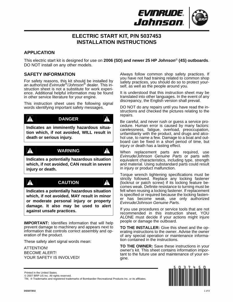
Tighten all four (4) starter bracket screws to 16.5ft. lbs. (23 N·m).
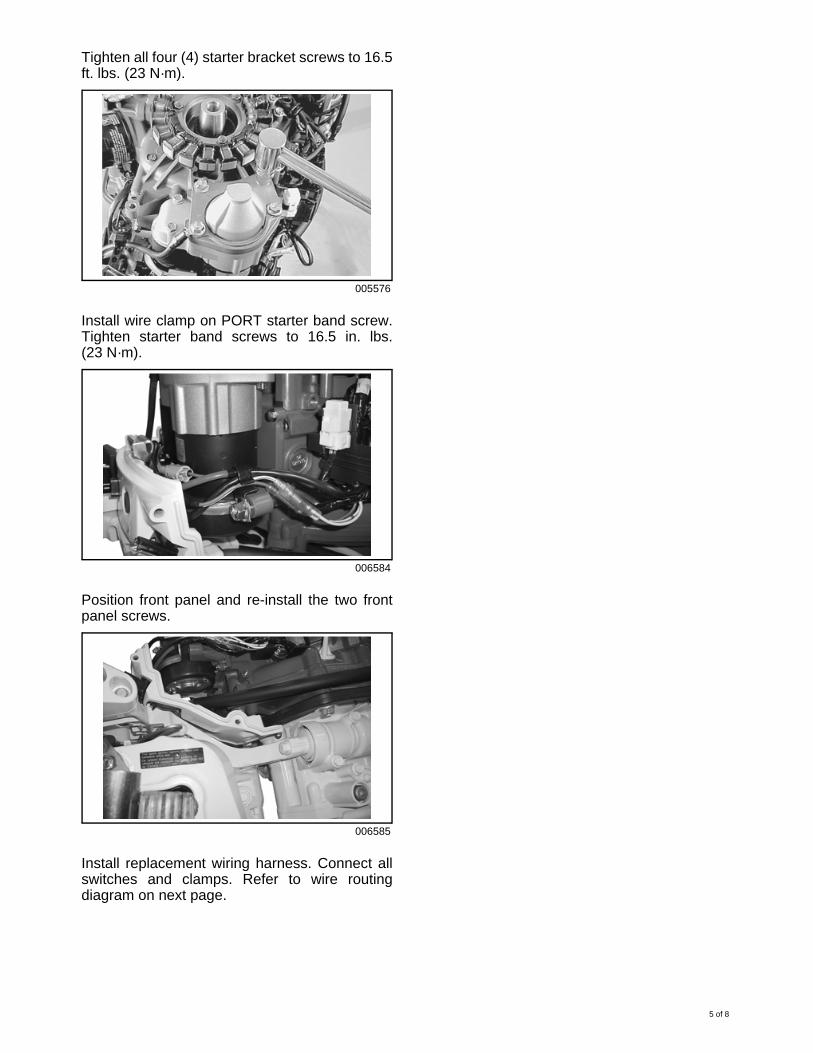
Install wire clamp on PORT starter band screw.Tighten starter band screws to 16.5 in. lbs.(23 N·m).
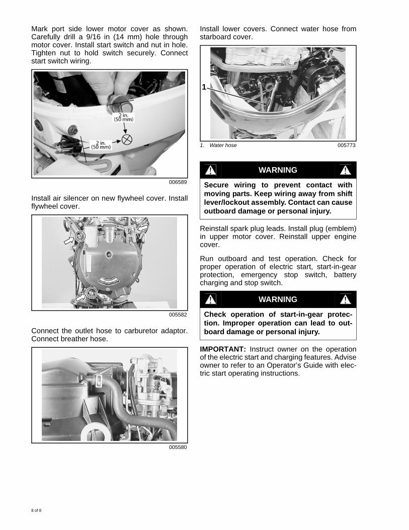
Position front panel and re-install the two frontpanel screws.
Install replacement wiring harness. Connect allswitches and clamps. Refer to wire routingdiagram on next page.
005576
006584
006585
5 of 8

WIRE ROUTING
Rou
te Ig
n. c
oil p
rimar
y le
ad o
n H
·T c
ord. R
ectif
ier
&re
gula
tor
Cla
mp
Igni
tion
coil
# I.C
KP
sen
sor
Igni
tion
coil
Sta
tor
lead
s sh
ould
be
pass
ed
thro
ugh
unde
r C
KP
sen
sor
Rec
oil s
tart
er m
odel
:P
ut li
ghtin
g co
il le
ad w
ires
into
ele
ctric
par
ts h
olde
r
Cla
mp
Cla
mp
#1 Ig
n. c
oil l
ead
Cla
mp
Bat
tery
cha
rge
&po
wer
sou
rce
coil
Fus
e ca
se a
ssem
bly
#2. C
KP
sen
sor C
DI u
nit
#2. C
KP
sen
sor
Blu
e tu
be
Cla
mp
6 of 8

Install stator and CKP sensors. Apply nut lock tothreads and tighten screws as follows:• 8 mm screws: 16.5 ft. lbs. (23 N·m)• 6 mm screws: 84 in. lbs. (10 N·m)
IMPORTANT: Do not pinch wiring during instal-lation.
Route wiring into electrical parts holder asshown. Connect starter relay to harness. Installgrommet on relay. Position relay and grommetand fuse holder in electrical bracket.
Connect wire harness connectors to CDI unit.Position CDI Unit with grommet in electricalbracket.
Install positive battery cable on “B” terminal ofstarter assembly and negative cable under frontstarboard starter bracket screw.
Open oval shaped hole in motor cover grommet.Route battery cables through oval hole ingrommet. Position wiring to prevent interferencewith shift linkage.
Clean mating surfaces of new flywheel andcrankshaft with cleaning solvent. Install newflywheel. Use flywheel holder and tighten bolt to142 ft. lbs. (196 N·m).
IMPORTANT: Perform final check of wire rout-ing and check all screws are tight. All wires mustbe clamped properly to prevent contact with ro-tating flywheel. Refer to wire routing diagram
005591
006586
006587
1. Negative cable 005572
006588
005593
1
7 of 8
Mark port side lower motor cover as shown.Carefully drill a 9/16 in (14 mm) hole throughmotor cover. Install start switch and nut in hole.Tighten nut to hold switch securely. Connectstart switch wiring.
Install air silencer on new flywheel cover. Installflywheel cover.
Connect the outlet hose to carburetor adaptor.Connect breather hose.
Install lower covers. Connect water hose fromstarboard cover.
Reinstall spark plug leads. Install plug (emblem)in upper motor cover. Reinstall upper enginecover.
Run outboard and test operation. Check forproper operation of electric start, start-in-gearprotection, emergency stop switch, batterycharging and stop switch.
IMPORTANT: Instruct owner on the operationof the electric start and charging features. Adviseowner to refer to an Operator’s Guide with elec-tric start operating instructions.
006589
005582
005580
1. Water hose 005773
WARNING
Secure wiring to prevent contact withmoving parts. Keep wiring away from shiftlever/lockout assembly. Contact can causeoutboard damage or personal injury.
WARNING
Check operation of start-in-gear protec-tion. Improper operation can lead to out-board damage or personal injury.
1
8 of 8