electric submersible pump systems - ge oil & gas ... submersible pump systems 7 ace plus gas...
TRANSCRIPT
GE Oil & Gas
Electric Submersible Pump Systems
2 Electric Submersible Pump Systems
ESP SYSTEMS
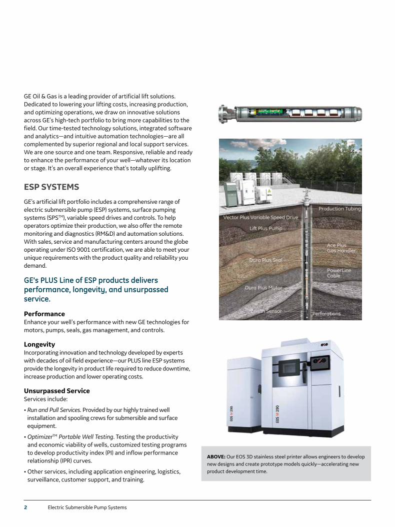
GE's artificial lift portfolio includes a comprehensive range of electric submersible pump (ESP) systems, surface pumping systems (SPSTM), variable speed drives and controls. To help operators optimize their production, we also offer the remote monitoring and diagnostics (RM&D) and automation solutions. With sales, service and manufacturing centers around the globe operating under ISO 9001 certification, we are able to meet your unique requirements with the product quality and reliability you demand.
GE's PLUS Line of ESP products delivers performance, longevity, and unsurpassed service.
PerformanceEnhance your well's performance with new GE technologies for motors, pumps, seals, gas management, and controls.
LongevityIncorporating innovation and technology developed by experts with decades of oil field experience—our PLUS line ESP systems provide the longevity in product life required to reduce downtime, increase production and lower operating costs.
Unsurpassed ServiceServices include:
• Run and Pull Services. Provided by our highly trained well installation and spooling crews for submersible and surface equipment.
• OptimizerTM Portable Well Testing. Testing the productivity and economic viability of wells, customized testing programs to develop productivity index (PI) and inflow performance relationship (IPR) curves.
• Other services, including application engineering, logistics, surveillance, customer support, and training.
GE Oil & Gas is a leading provider of artificial lift solutions. Dedicated to lowering your lifting costs, increasing production, and optimizing operations, we draw on innovative solutions across GE's high-tech portfolio to bring more capabilities to the field. Our time-tested technology solutions, integrated software and analytics—and intuitive automation technologies—are all complemented by superior regional and local support services. We are one source and one team. Responsive, reliable and ready to enhance the performance of your well—whatever its location or stage. It's an overall experience that's totally uplifting.
ABOVE: Our EOS 3D stainless steel printer allows engineers to develop new designs and create prototype models quickly—accelerating new product development time.
Electric Submersible Pump Systems 3
# of Models
Pump Capacities Flow Range✝
Pump Series OD (in mm) Min Casing (in mm) 60 Hz bpd 50 Hz m3/d
6 3.38/TA 3.38 (85.9) 4.500 (114.3) 300–3400 40–450
13 4.00/TD 4.00 (101.6) 5.500 (139.7) 80–7500 11–994
7 5.38/TE 5.38 (136.7) 7.000 (137.8) 800–14000 106–1855
2 5.62/TH 5.63 (143.0) 7.000 (137.8) 9000–23500 1192–3144
4 6.75/TJ 6.75 (171.5) 8.625 (219.1) 5000–26000 662–3445
1 8.62/TM 8.63 (219.2) 10.750 (253.1) 12500–34000 1656–4505
1 9.50/TN 9.50 (241.3) 11.750 (298.5) 2500–45000 3378–5962
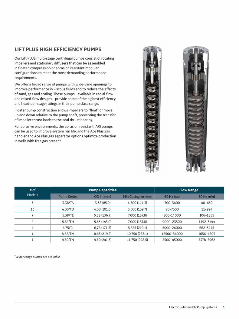
LIFT PLUS HIGH EFFICIENCY PUMPS
Our Lift PLUS multi-stage centrifugal pumps consist of rotating impellers and stationary diffusers that can be assembled in floater, compression or abrasion resistant modular configurations to meet the most demanding performance requirements.
We offer a broad range of pumps with wide-vane openings to improve performance in viscous fluids and to reduce the effects of sand, gas and scaling. These pumps—available in radial-flow and mixed-flow designs—provide some of the highest efficiency and head-per-stage ratings in their pump class range.
Floater pump construction allows impellers to “float” or move up and down relative to the pump shaft, preventing the transfer of impeller thrust loads to the seal thrust bearing.
For abrasive environments, the abrasion resistant (AR) pumps can be used to improve system run life, and the Ace Plus gas handler and Ace Plus gas separator options optimize production in wells with free gas present.
✝Wider range pumps are available.
4 Electric Submersible Pump Systems4 Electric Submersible Pump Systems
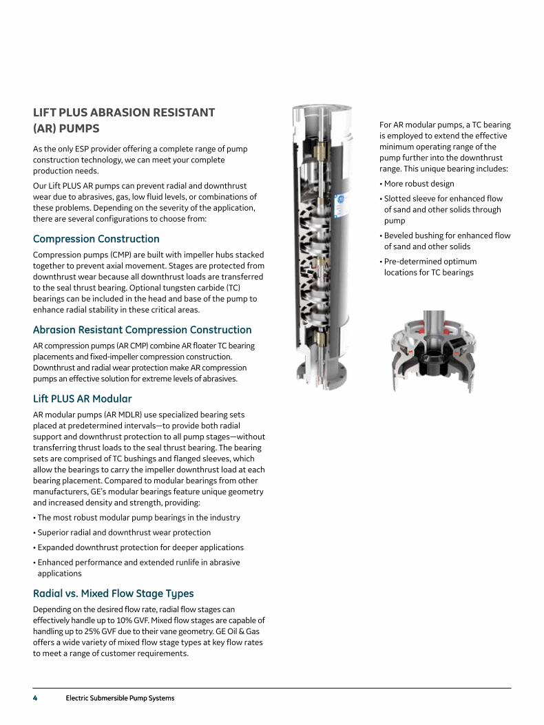
LIFT PLUS ABRASION RESISTANT (AR) PUMPS
As the only ESP provider offering a complete range of pump construction technology, we can meet your complete production needs.
Our Lift PLUS AR pumps can prevent radial and downthrust wear due to abrasives, gas, low fluid levels, or combinations of these problems. Depending on the severity of the application, there are several configurations to choose from:
Compression ConstructionCompression pumps (CMP) are built with impeller hubs stacked together to prevent axial movement. Stages are protected from downthrust wear because all downthrust loads are transferred to the seal thrust bearing. Optional tungsten carbide (TC) bearings can be included in the head and base of the pump to enhance radial stability in these critical areas.
Abrasion Resistant Compression ConstructionAR compression pumps (AR CMP) combine AR floater TC bearing placements and fixed-impeller compression construction. Downthrust and radial wear protection make AR compression pumps an effective solution for extreme levels of abrasives.
Lift PLUS AR ModularAR modular pumps (AR MDLR) use specialized bearing sets placed at predetermined intervals—to provide both radial support and downthrust protection to all pump stages—without transferring thrust loads to the seal thrust bearing. The bearing sets are comprised of TC bushings and flanged sleeves, which allow the bearings to carry the impeller downthrust load at each bearing placement. Compared to modular bearings from other manufacturers, GE's modular bearings feature unique geometry and increased density and strength, providing:
• The most robust modular pump bearings in the industry
• Superior radial and downthrust wear protection
• Expanded downthrust protection for deeper applications
• Enhanced performance and extended runlife in abrasive applications
Radial vs. Mixed Flow Stage TypesDepending on the desired flow rate, radial flow stages can effectively handle up to 10% GVF. Mixed flow stages are capable of handling up to 25% GVF due to their vane geometry. GE Oil & Gas offers a wide variety of mixed flow stage types at key flow rates to meet a range of customer requirements.
For AR modular pumps, a TC bearing is employed to extend the effective minimum operating range of the pump further into the downthrust range. This unique bearing includes:
• More robust design
• Slotted sleeve for enhanced flow of sand and other solids through pump
• Beveled bushing for enhanced flow of sand and other solids
• Pre-determined optimum locations for TC bearings
Electric Submersible Pump Systems 5 Electric Submersible Pump Systems 5
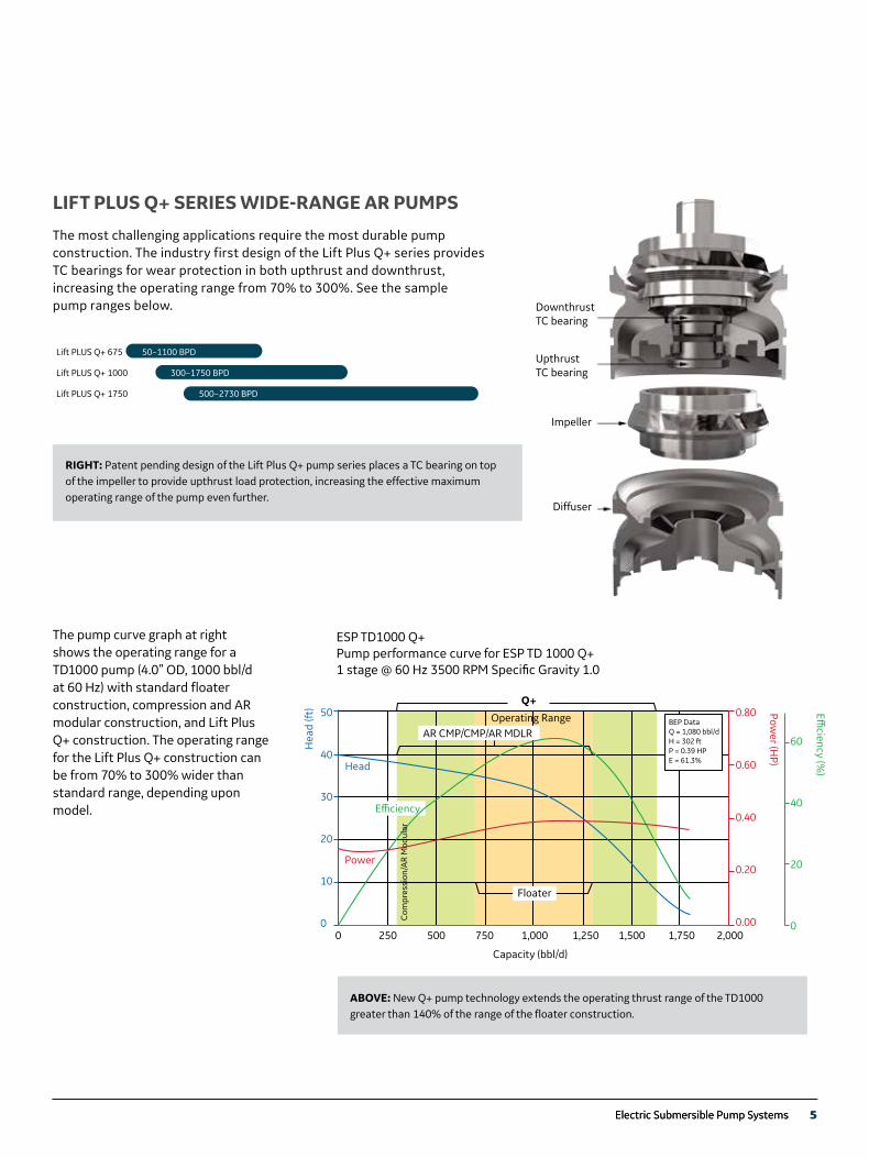
LIFT PLUS Q+ SERIES WIDE-RANGE AR PUMPS
The most challenging applications require the most durable pump construction. The industry first design of the Lift Plus Q+ series provides TC bearings for wear protection in both upthrust and downthrust, increasing the operating range from 70% to 300%. See the sample pump ranges below.
The pump curve graph at right shows the operating range for a TD1000 pump (4.0” OD, 1000 bbl/d at 60 Hz) with standard floater construction, compression and AR modular construction, and Lift Plus Q+ construction. The operating range for the Lift Plus Q+ construction can be from 70% to 300% wider than standard range, depending upon model.
ESP TD1000 Q+Pump performance curve for ESP TD 1000 Q+1 stage @ 60 Hz 3500 RPM Speci�c Gravity 1.0
0 250 500 750 1,000 1,250 1,500 1,750 2,000
Capacity (bbl/d)
50
40
30
20
10
0
0.80
0.60
0.40
0.20
0.00
60
40
20
0
AR CMP/CMP/AR MDLRBEP DataQ = 1,080 bbl/dH = 302 ftP = 0.39 HPE = 61.3%
Hea
d (ft
)
Com
pres
sion
/AR
Mod
ular
Head
Power
Operating Range
Q+
E�ciency (%
)
Power (H
P)
Floater
E�ciency
Upthrust TC bearing
Impeller
Diffuser
Downthrust TC bearing
RIGHT: Patent pending design of the Lift Plus Q+ pump series places a TC bearing on top of the impeller to provide upthrust load protection, increasing the effective maximum operating range of the pump even further.
ABOVE: New Q+ pump technology extends the operating thrust range of the TD1000 greater than 140% of the range of the floater construction.
Lift PLUS Q+ 675
Lift PLUS Q+ 1000
Lift PLUS Q+ 1750
50–1100 BPD
300–1750 BPD
500–2730 BPD
6 Electric Submersible Pump Systems
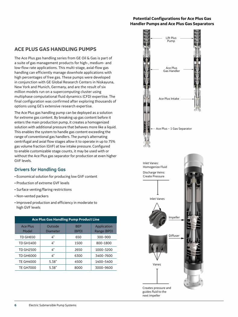
ACE PLUS GAS HANDLING PUMPS
The Ace Plus gas handling series from GE Oil & Gas is part of a suite of gas management products for high-, medium- and low-flow rate applications. This multi-stage, axial-flow gas handling can efficiently manage downhole applications with high percentages of free gas. These pumps were developed in conjunction with GE Global Research Centers in Niskayuna, New York and Munich, Germany, and are the result of six million models run on a supercomputing cluster using multiphase computational fluid dynamics (CFD) expertise. The final configuration was confirmed after exploring thousands of options using GE’s extensive research expertise.
The Ace Plus gas handling pump can be deployed as a solution for extreme gas content. By breaking up gas content before it enters the main production pump, it creates a homogenized solution with additional pressure that behaves more like a liquid. This enables the system to handle gas content exceeding the range of conventional gas handlers. The pump’s alternating centrifugal and axial flow stages allow it to operate in up to 75% gas volume fraction (GVF) at low intake pressure. Configured to enable customizable stage counts, it may be used with or without the Ace Plus gas separator for production at even higher GVF levels.
Drivers for Handling Gas• Economical solution for producing low GVF content
• Production of extreme GVF levels
• Surface venting/flaring restrictions
• Non-vented packers
• Improved production and efficiency in moderate to high GVF levels
Potential Configurations for Ace Plus Gas Handler Pumps and Ace Plus Gas Separators
Lift Plus Pump
Ace Plus Intake
Ace Plus – 1 Gas Separator
Ace Plus Gas Handler
Ace Plus Gas Handling Pump Product Line
Ace Plus Model
Outside Diameter
BEP (BPD)
Application Range (BPD)
TD GH650 4” 650 300–900
TD GH1400 4” 1500 800–1800
TD GH2500 4” 2650 1000–3200
TD GH6000 4” 6300 3400–7600
TE GH4000 5.38” 4500 1400–5400
TE GH7000 5.38” 8000 3000–9600
Inlet Vanes: Homogenize Fluid
Discharge Veins: Create Pressure
Creates pressure and guides fluid to the next impeller
Inlet Vanes
Vanes
Diffuser
Impeller
Electric Submersible Pump Systems 7
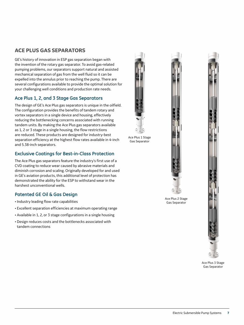
ACE PLUS GAS SEPARATORS
GE’s history of innovation in ESP gas separation began with the invention of the rotary gas separator. To avoid gas-related pumping problems, our separators support natural and assisted mechanical separation of gas from the well fluid so it can be expelled into the annulus prior to reaching the pump. There are several configurations available to provide the optimal solution for your challenging well conditions and production rate needs.
Ace Plus 1, 2, and 3 Stage Gas SeparatorsThe design of GE’s Ace Plus gas separators is unique in the oilfield. The configuration provides the benefits of tandem rotary and vortex separators in a single device and housing, effectively reducing the bottlenecking concerns associated with running tandem units. By making the Ace Plus gas separators available as 1, 2 or 3 stage in a single housing, the flow restrictions are reduced. These products are designed for industry-best separation efficiency at the highest flow rates available in 4-inch and 5.38-inch separators.
Exclusive Coatings for Best-in-Class ProtectionThe Ace Plus gas separators feature the industry's first use of a CVD coating to reduce wear caused by abrasive materials and diminish corrosion and scaling. Originally developed for and used in GE's aviation products, this additional level of protection has demonstrated the ability for the ESP to withstand wear in the harshest unconventional wells.
Patented GE Oil & Gas Design• Industry leading flow rate capabilities
• Excellent separation efficiencies at maximum operating range
• Available in 1, 2, or 3 stage configurations in a single housing
• Design reduces costs and the bottlenecks associated with tandem connections
Ace Plus 1 Stage Gas Separator
Ace Plus 2 Stage Gas Separator
Ace Plus 3 Stage Gas Separator
8 Electric Submersible Pump Systems
Dura PlusTM High-Efficiency Extra High Temperature Submersible Motors GE provides Dura PlusTM 456 series extra high temperature (XHT) and 562 series XHT motors for operation in the most demanding wells, such as SAGD applications. New generation ESP components have been redesigned with improved insulation materials and new bearing materials to improve radial stability to help withstand extreme well conditions. GE’s Dura PlusTM XHT systems tolerate the extreme temperature swing from the subfreezing surface to the severe heat of bottom-hole temperatures (BHT rated for 230°C ambient) and have been engineered and manufactured to provide greater reliability in high temperatures.
Motor Size OD 60 Hz HP 50 Hz HP
E37 (3.75”) 15–270 12.5–225
Dura PlusTM 456 (4.56”) 19–500 15.6–417
Dura PlusTM 562 (5.62”) 38–950 31.25–792
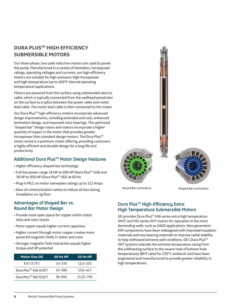
DURA PLUSTM HIGH EFFICIENCY SUBMERSIBLE MOTORS
Our three-phase, two-pole induction motors are used to power the pump. Manufactured in a variety of diameters, horsepower ratings, operating voltages and currents, our high-efficiency motors are suitable for high-pressure, high-horsepower and high-temperature (up to 400°F internal operating temperature) applications.
Motors are powered from the surface using submersible electric cable, which is typically connected from the wellhead penetrator on the surface to a splice between the power cable and motor lead cable. The motor lead cable is then connected to the motor.
Our Dura PlusTM high-efficiency motors incorporate advanced design improvements, including extended end coils, enhanced lamination design, and improved rotor bearings. The optimized “shaped bar” design rotors and stators incorporate a higher quantity of copper in the motor that provides greater horsepower than standard design motors. The Dura PlusTM motor series is a premium motor offering, providing customers a highly efficient and durable design for a long life and productivity.
Additional Dura PlusTM Motor Design Features• Higher efficiency shaped-bar technology
• Full line power range 19 HP to 500 HP (Dura PlusTM 456) and 38 HP to 950 HP (Dura PlusTM 562) at 60 Hz
• Plug-in MLC on motor nameplate ratings up to 112 Amps
• New oil communication valves to reduce oil loss during installation on rig floor
Advantages of Shaped Bar vs. Round Bar Motor Design• Provide more open space for copper within stator
slots and rotor stacks
• More copper equals higher current capacities
• Higher current through motor copper creates more powerful magnetic fields in stator and rotor
• Stronger magnetic field interaction equals higher torque and HP potential
Round Bar Lamination Shaped Bar Lamination
Electric Submersible Pump Systems 9
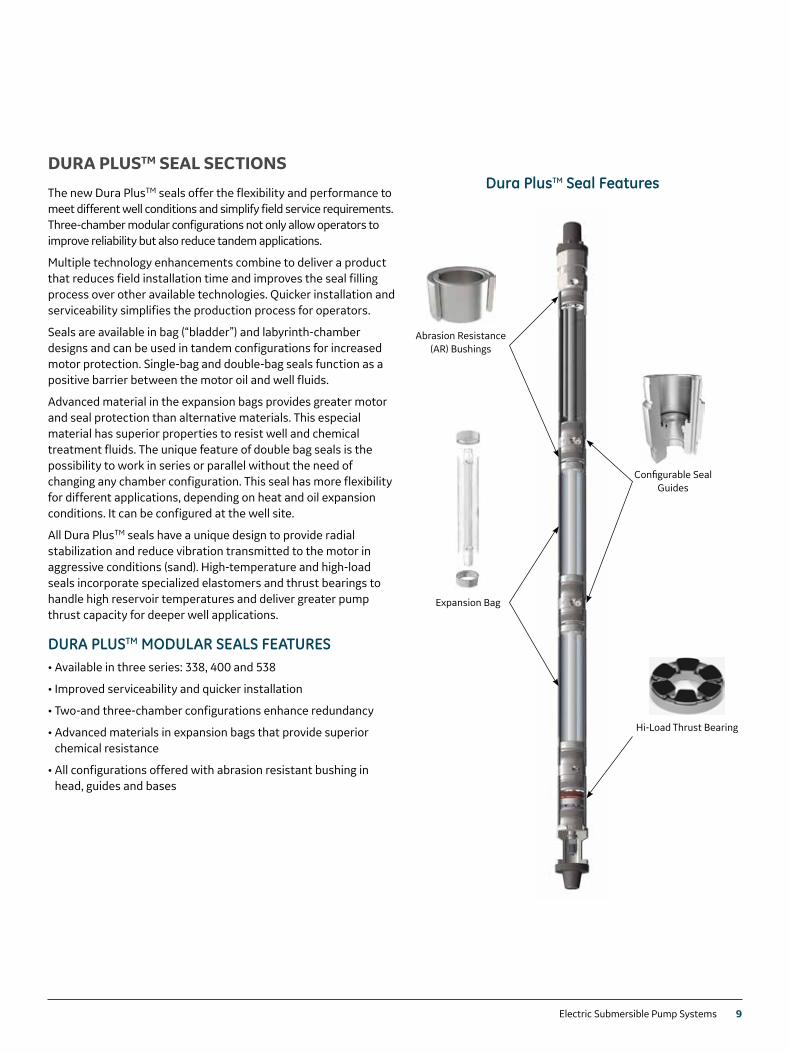
DURA PLUSTM SEAL SECTIONS
The new Dura PlusTM seals offer the flexibility and performance to meet different well conditions and simplify field service requirements. Three-chamber modular configurations not only allow operators to improve reliability but also reduce tandem applications.
Multiple technology enhancements combine to deliver a product that reduces field installation time and improves the seal filling process over other available technologies. Quicker installation and serviceability simplifies the production process for operators.
Seals are available in bag (“bladder”) and labyrinth-chamber designs and can be used in tandem configurations for increased motor protection. Single-bag and double-bag seals function as a positive barrier between the motor oil and well fluids.
Advanced material in the expansion bags provides greater motor and seal protection than alternative materials. This especial material has superior properties to resist well and chemical treatment fluids. The unique feature of double bag seals is the possibility to work in series or parallel without the need of changing any chamber configuration. This seal has more flexibility for different applications, depending on heat and oil expansion conditions. It can be configured at the well site.
All Dura PlusTM seals have a unique design to provide radial stabilization and reduce vibration transmitted to the motor in aggressive conditions (sand). High-temperature and high-load seals incorporate specialized elastomers and thrust bearings to handle high reservoir temperatures and deliver greater pump thrust capacity for deeper well applications.
DURA PLUSTM MODULAR SEALS FEATURES• Available in three series: 338, 400 and 538
• Improved serviceability and quicker installation
• Two-and three-chamber configurations enhance redundancy
• Advanced materials in expansion bags that provide superior chemical resistance
• All configurations offered with abrasion resistant bushing in head, guides and bases
Dura PlusTM Seal Features
Abrasion Resistance (AR) Bushings
Expansion Bag
Configurable Seal Guides
Hi-Load Thrust Bearing
10 Electric Submersible Pump Systems
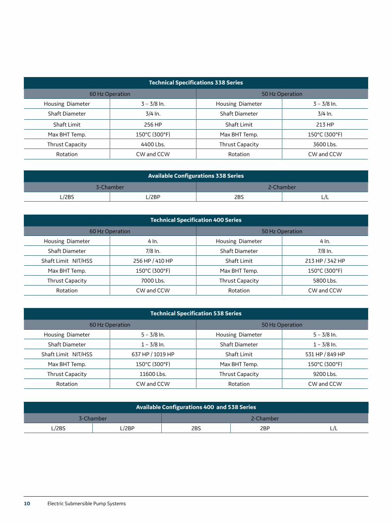
Technical Specifications 338 Series
60 Hz Operation 50 Hz Operation
Housing Diameter 3 – 3/8 In. Housing Diameter 3 – 3/8 In.
Shaft Diameter 3/4 In. Shaft Diameter 3/4 In.
Shaft Limit 256 HP Shaft Limit 213 HP
Max BHT Temp. 150°C (300°F) Max BHT Temp. 150°C (300°F)
Thrust Capacity 4400 Lbs. Thrust Capacity 3600 Lbs.
Rotation CW and CCW Rotation CW and CCW
Available Configurations 338 Series
3-Chamber 2-Chamber
L/2BS L/2BP 2BS L/L
Available Configurations 400 and 538 Series
3-Chamber 2-Chamber
L/2BS L/2BP 2BS 2BP L/L
Technical Specification 400 Series
60 Hz Operation 50 Hz Operation
Housing Diameter 4 In. Housing Diameter 4 In.
Shaft Diameter 7/8 In. Shaft Diameter 7/8 In.
Shaft Limit NIT/HSS 256 HP / 410 HP Shaft Limit 213 HP / 342 HP
Max BHT Temp. 150°C (300°F) Max BHT Temp. 150°C (300°F)
Thrust Capacity 7000 Lbs. Thrust Capacity 5800 Lbs.
Rotation CW and CCW Rotation CW and CCW
Technical Specification 538 Series
60 Hz Operation 50 Hz Operation
Housing Diameter 5 – 3/8 In. Housing Diameter 5 – 3/8 In.
Shaft Diameter 1 – 3/8 In. Shaft Diameter 1 – 3/8 In.
Shaft Limit NIT/HSS 637 HP / 1019 HP Shaft Limit 531 HP / 849 HP
Max BHT Temp. 150°C (300°F) Max BHT Temp. 150°C (300°F)
Thrust Capacity 11600 Lbs. Thrust Capacity 9200 Lbs.
Rotation CW and CCW Rotation CW and CCW
Electric Submersible Pump Systems 11
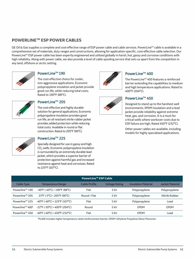
POWERLINETM ESP POWER CABLES
GE Oil & Gas supplies a complete and cost-effective range of ESP power cable and cable services. PowerLineTM cable is available in a comprehensive set of materials, duty ranges and constructions, allowing for application-specific, cost-effective cable selection. Our PowerLineTM ESP power cable has been expertly engineered and utilized globally in harsh, hot, gassy and corrosive conditions with high reliability. Along with power cable, we also provide a level of cable spooling service that sets us apart from the competition in any land, offshore or arctic setting.
PowerLineTM ESP Cable
Cable Type Temperature Range Cable Profile Voltage Rating Insulation Material Jacket Material
PowerlineTM 190 -40ºF (-40ºC) • 190ºF (88ºC) Flat 3 kV Polypropylene Polypropylene
PowerlineTM 205 23ºF (-5ºC) • 205ºF (96ºC) Round • Flat 5 kV Polypropylene Nitrile Rubber
PowerlineTM 225 -40ºF (-40ºC) • 225ºF (107ºC) Flat 5 kV Polypropylene Lead
PowerlineTM 400✝ -22ºF (-30ºC) • 400ºF (204ºC) Round 5 kV EPDM EPDM
PowerlineTM 450 -40ºF (-40ºC) • 450ºF (232ºC) Flat 5 kV EPDM Lead
✝PL400 includes higher temperature rated reinforcement barrier. EPDM–Ethylene Propylene Diene Monomer.
PowerLineTM 190The cost-effective choice for cooler, non-aggressive applications. Economic polypropylene insulation and jacket provide good run life, while reducing total costs. Rated to 190ºF (88ºC).
PowerLineTM 205The cost-effective and highly durable solution for general applications. Economic polypropylene insulation provides good run life, an oil resistant nitrile rubber jacket provides added protection while reducing total costs. Available in round or flat construction. Rated to 205ºF (96ºC).
PowerLineTM 225Specially designed for use in gassy and high CO2 wells. Economic polypropylene insulation is surrounded by an extremely durable lead jacket, which provides a superior barrier of protection against harmful gas and increased resistance against heat and corrosives. Rated to 225ºF (107ºC).
PowerLineTM 400The PowerLineTM 400 features a reinforced barrier extending the capabilities to medium and high temperature applications. Rated to 400ºF (204ºC).
PowerLineTM 450Designed to stand up to the harshest well environments. EPDM insulation and a lead jacket provide reliability against extreme heat, gas, and corrosion. It is a must for critical wells where workover costs due to ESP failure are high. Rated 450ºF (232ºC).
Other power cables are available, including models for highly specialized applications.
11 Electric Submersible Pump Systems
12 Electric Submersible Pump Systems
VARIABLE SPEED DRIVES AND FIXED SPEED DRIVES
GE Oil & Gas offers a wide variety of surface control equipment to help you increase production and reduce operating costs.
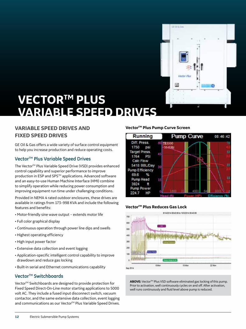
VectorTM Plus Variable Speed DrivesThe VectorTM Plus Variable Speed Drive (VSD) provides enhanced control capability and superior performance to improve production in ESP and SPSTM applications. Advanced software and an easy-to-use Human Machine Interface (HMI) combine to simplify operation while reducing power consumption and improving equipment run time under challenging conditions.
Provided in NEMA 4 rated outdoor enclosures, these drives are available in ratings from 173–998 KVA and include the following features and benefits:
• Motor-friendly sine wave output – extends motor life
• Full color graphical display
• Continuous operation through power line dips and swells
• Highest operating efficiency
• High input power factor
• Extensive data collection and event logging
• Application-specific intelligent control capability to improve drawdown and reduce gas locking
• Built-in serial and Ethernet communications capability
VectorTM Switchboards VectorTM Switchboards are designed to provide protection for Fixed Speed Direct-On-Line motor starting applications to 5000 volt AC. They include a fused input disconnect switch, vacuum contactor, and the same extensive data collection, event logging and communications as our VectorTM Plus Variable Speed Drives.
VectorTM Plus Pump Curve Screen
VectorTM Plus Reduces Gas Lock
ABOVE: VectorTM Plus VSD software eliminated gas locking of this pump. Prior to activation, well continuously cycles on and off. After activation, well runs continuously and fluid level above pump is reduced.
VECTORTM PLUS VARIABLE SPEED DRIVES
Electric Submersible Pump Systems 13
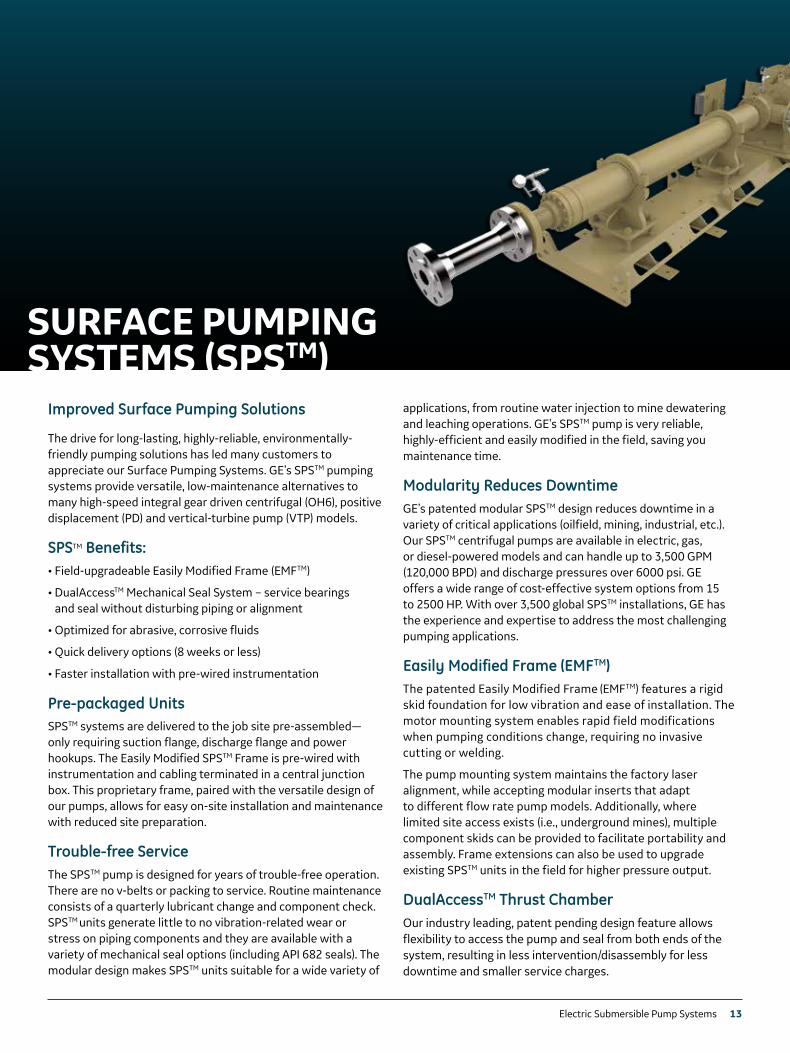
Improved Surface Pumping Solutions
The drive for long-lasting, highly-reliable, environmentally-friendly pumping solutions has led many customers to appreciate our Surface Pumping Systems. GE’s SPSTM pumping systems provide versatile, low-maintenance alternatives to many high-speed integral gear driven centrifugal (OH6), positive displacement (PD) and vertical-turbine pump (VTP) models.
SPSTM Benefits:• Field-upgradeable Easily Modified Frame (EMFTM)
• DualAccessTM Mechanical Seal System – service bearings and seal without disturbing piping or alignment
• Optimized for abrasive, corrosive fluids
• Quick delivery options (8 weeks or less)
• Faster installation with pre-wired instrumentation
Pre-packaged UnitsSPSTM systems are delivered to the job site pre-assembled—only requiring suction flange, discharge flange and power hookups. The Easily Modified SPSTM Frame is pre-wired with instrumentation and cabling terminated in a central junction box. This proprietary frame, paired with the versatile design of our pumps, allows for easy on-site installation and maintenance with reduced site preparation.
Trouble-free ServiceThe SPSTM pump is designed for years of trouble-free operation. There are no v-belts or packing to service. Routine maintenance consists of a quarterly lubricant change and component check. SPSTM units generate little to no vibration-related wear or stress on piping components and they are available with a variety of mechanical seal options (including API 682 seals). The modular design makes SPSTM units suitable for a wide variety of
SURFACE PUMPING SYSTEMS (SPSTM)
applications, from routine water injection to mine dewatering and leaching operations. GE's SPSTM pump is very reliable, highly-efficient and easily modified in the field, saving you maintenance time.
Modularity Reduces DowntimeGE’s patented modular SPSTM design reduces downtime in a variety of critical applications (oilfield, mining, industrial, etc.). Our SPSTM centrifugal pumps are available in electric, gas, or diesel-powered models and can handle up to 3,500 GPM (120,000 BPD) and discharge pressures over 6000 psi. GE offers a wide range of cost-effective system options from 15 to 2500 HP. With over 3,500 global SPSTM installations, GE has the experience and expertise to address the most challenging pumping applications.
Easily Modified Frame (EMFTM)The patented Easily Modified Frame (EMFTM) features a rigid skid foundation for low vibration and ease of installation. The motor mounting system enables rapid field modifications when pumping conditions change, requiring no invasive cutting or welding.
The pump mounting system maintains the factory laser alignment, while accepting modular inserts that adapt to different flow rate pump models. Additionally, where limited site access exists (i.e., underground mines), multiple component skids can be provided to facilitate portability and assembly. Frame extensions can also be used to upgrade existing SPSTM units in the field for higher pressure output.
DualAccessTM Thrust ChamberOur industry leading, patent pending design feature allows flexibility to access the pump and seal from both ends of the system, resulting in less intervention/disassembly for less downtime and smaller service charges.
14 Electric Submersible Pump Systems
IMPROVE YOUR ESP OPERATIONS
Field VantageTM software can help you improve the operation of your ESP systems. In oilfield production operations, data-driven insights enable faster and more informed decisions, empowering you to lower lifting costs, meet production targets and operate safer. Powered by GE's PredixTM operating system, Field VantageTM goes beyond traditional systems’ data streams and alarms to offer unique software solution that provides situational intelligence on all your wells to help run your operation at maximum efficiency.
The Field VantageTM software solution continually analyzes your well performance, identifies opportunities for improvement and notifies you of wells that need attention. This unburdens you from looking through data well-by-well, and lets you concentrate on executing operational improvements that make real financial impacts to your operation.
Field VantageTM is a simple yet powerful tool designed by operators for operators. Highlights include:
• A simple yet comprehensive real-time view of your artificial lift operations
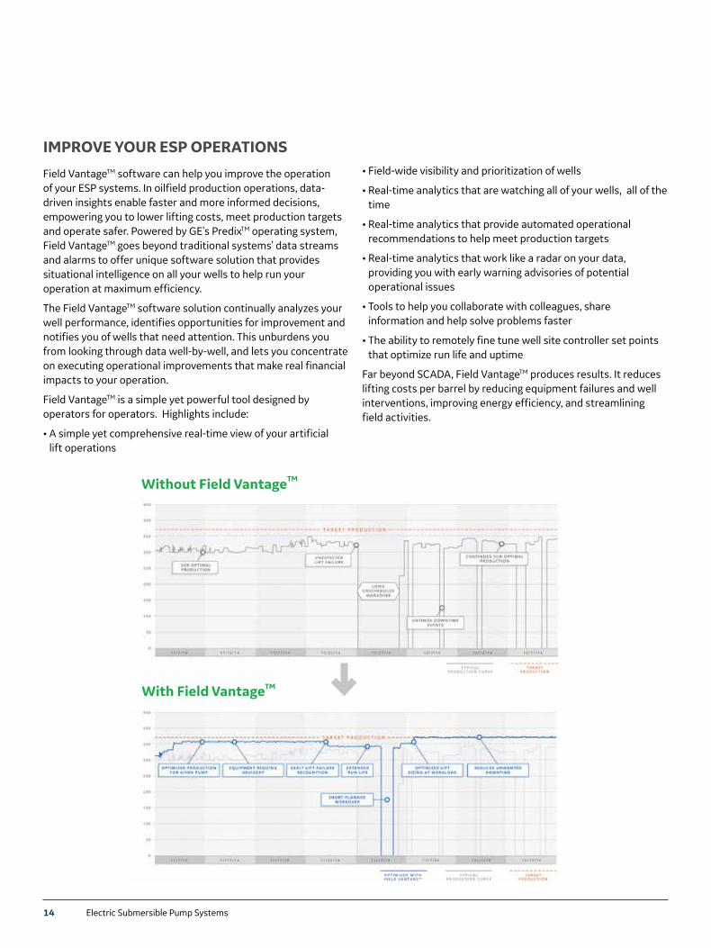
Without Field Vantage
Suboptimal production
Long unplanned workover
Prod
uctio
n
Unplanned failureExpected well production
Returned to suboptimal production Early failure detectionExtend run life
Optimize production
With Field Vantage
Short planned workover
Prod
uctio
n
Without Field Vantage
Suboptimal production
Long unplanned workover
Prod
uctio
n
Unplanned failureExpected well production
Returned to suboptimal production Early failure detectionExtend run life
Optimize production
With Field Vantage
Short planned workover
Prod
uctio
n
• Field-wide visibility and prioritization of wells
• Real-time analytics that are watching all of your wells, all of the time
• Real-time analytics that provide automated operational recommendations to help meet production targets
• Real-time analytics that work like a radar on your data, providing you with early warning advisories of potential operational issues
• Tools to help you collaborate with colleagues, share information and help solve problems faster
• The ability to remotely fine tune well site controller set points that optimize run life and uptime
Far beyond SCADA, Field VantageTM produces results. It reduces lifting costs per barrel by reducing equipment failures and well interventions, improving energy efficiency, and streamlining field activities.
TM
TM
Electric Submersible Pump Systems 15
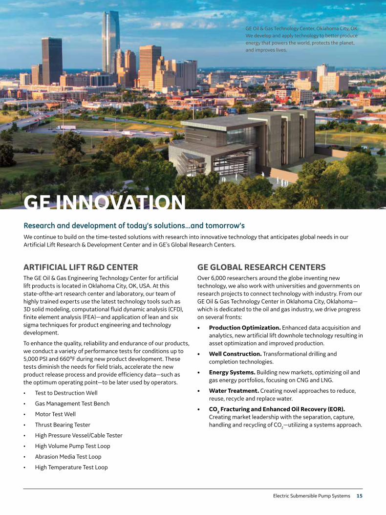
GE Oil & Gas Technology Center, Oklahoma City, OK. We develop and apply technology to better produce energy that powers the world, protects the planet, and improves lives.
The GE Oil & Gas Engineering Technology Center for artificial lift products is located in Oklahoma City, OK, USA. At this state-ofthe-art research center and laboratory, our team of highly trained experts use the latest technology tools such as 3D solid modeling, computational fluid dynamic analysis (CFD), finite element analysis (FEA)—and application of lean and six sigma techniques for product engineering and technology development.
To enhance the quality, reliability and endurance of our products, we conduct a variety of performance tests for conditions up to 5,000 PSI and 660ºF during new product development. These tests diminish the needs for field trials, accelerate the new product release process and provide efficiency data—such as the optimum operating point—to be later used by operators.
• Test to Destruction Well
• Gas Management Test Bench
• Motor Test Well
• Thrust Bearing Tester
• High Pressure Vessel/Cable Tester
• High Volume Pump Test Loop
• Abrasion Media Test Loop
• High Temperature Test Loop
Over 6,000 researchers around the globe inventing new technology, we also work with universities and governments on research projects to connect technology with industry. From our GE Oil & Gas Technology Center in Oklahoma City, Oklahoma—which is dedicated to the oil and gas industry, we drive progress on several fronts:
• Production Optimization. Enhanced data acquisition and analytics, new artificial lift downhole technology resulting in asset optimization and improved production.
• Well Construction. Transformational drilling and completion technologies.
• Energy Systems. Building new markets, optimizing oil and gas energy portfolios, focusing on CNG and LNG.
• Water Treatment. Creating novel approaches to reduce, reuse, recycle and replace water.
• CO2 Fracturing and Enhanced Oil Recovery (EOR). Creating market leadership with the separation, capture, handling and recycling of CO2—utilizing a systems approach.
Research and development of today’s solutions…and tomorrow’sWe continue to build on the time-tested solutions with research into innovative technology that anticipates global needs in our Artificial Lift Research & Development Center and in GE’s Global Research Centers.
GE INNOVATION
ARTIFICIAL LIFT R&D CENTER GE GLOBAL RESEARCH CENTERS
16 Electric Submersible Pump Systems
© 2016 General Electric Company. All rights reserved.The GE Monogram, SPS, Optimizer, Dura Plus, PowerLine, Vector, EMF, Field Vantage, DualAccess, and Predix are trademarks of General Electric Company in the United States and/or other countries.
GEA31763C (12/2016)
For more information, please contact your GE sales representative.
GE Oil & Gas
5500 SE 59th St
Oklahoma City, OK 73135
405.670.1431
www.geoilandgas.com