electric welding effect: detection via phototube … · 1 electric welding effect: detection via...
TRANSCRIPT

1
ELECTRIC WELDING EFFECT:
DETECTION VIA PHOTOTUBE SENSOR
AND MAINTENANCE ACTIVITIES
Aldo BALESTRINO(#), Ottorino BRUNO(#), Pierpaolo GIORGI(°),Alberto LANDI(#), Mauro PAPI(§), Luca SANI(#), Angelo GiuseppeVIOLI(§)
(#)Dipartimento di Sistemi Elettrici e AutomazioneUniversitá di Pisa, Via Diotisalvi 2, 56126 PISA, Italy
Tel: +39-050-565111, Fax: +39-050-565333, e-mail: [email protected](§)Trenitalia S.p.A. - Unitá Tecnologie Materiale Rotabile
Sperimentazione - Prove ElettricheViale Spartaco Lavagnini 58, 50129 Firenze, Italy
Tel: +39-055-2353379, Fax: +39-055-2353522, e-mail: [email protected](°)RFI - Direzione Manutenzione – Ingegneria di Manutenzione Energia
e Trazione ElettricaPiazza della Croce Rossa 1, 00161 Roma, Italy
Tel: +39 06 44249304, Fax: +39 06 44104412, e-mail: [email protected]
SummaryA crucial problem for railway companies is to prevent damage to the overhead
line equipment and to pantographs. Unfortunately high speeds worsen the problem anda monitoring system has to be set up and tested to plan maintenance activities. Testruns were performed on board of an ETR500, a high-speed train of Italian Railways,with a double pantograph and an acquisition system on board of a measurement coach,based on a twin phototube sensor. Besides critical points of the overhead line, due tobreak arcs, it was revealed that the current collection between pantograph and overheadline is of a poor quality in the presence of a continuous flashing (the electric welding ef-fect). Aim of the paper is to investigate the impact of such phenomenon on the overheadcontact lines. Photographs from a visual inspection of the line are included to demon-strate both the line deterioration due to the electric welding effect, and the reliability ofthe twin phototube sensor for planning maintenance activities.
KeywordsInnovative sensor, quality of current collection, catenary/pantograph interaction, photo-tube, maintenance.

2
1 Introduction: quality of current collection
For high-speed trains a regular contact is very difficult to achieve, especially in the Ital-
ian railways, where the supply voltage is low (3 kV D.C.) and where a pantograph for
high-speed operation (250-300 km/h) is required to collect currents up to 2500 A.
High quality current collection is characterized by a continuous contact between the
pantograph and the overhead line. A poor contact produces various drawbacks, includ-
ing break arcs, excessive wear of the pantograph strips and of the contact wire, bounces
against swivel cantilevers and fixed parts of the line. High speeds worsen these negative
aspects: the higher speeds, the more critical the problems. Over 200 km/h, wires start
waving and the pantograph head can’t stay in contact, in case of abrupt height varia-
tions. More than one pantograph on a train worsens the problem of waving wires for the
rear pantograph: it encounters an overhead line already excited by the first one, so that
the quality of the contact deteriorates. In order to collect high currents at high speeds
and reduce deterioration due to break arcs, different solutions are applied:
1) increasing the uplift contact force between the pantograph and the contact wire, at
the expense of a reduction of the life-time of the collector strips and particularly of
the contact wire, because of erosive and abrasive wear and of temperature raising;
2) a reduction of the pantograph head mass. Unfortunately the high currents transmit-
ted limit such a reduction;
3) a new design of the overhead system; such an approach is only alleviating the prob-
lem and it is too expensive where existing systems are to be modified.
Anyway a good quality contact can be achieved maintaining geometrical characteristics
of the line within optimal values [1], e.g. limiting as far as possible height variations and
staggering of the overhead contact wires, and checking thickness of the contact wire.
Such tasks are fulfilled only intensifying the frequency of periodical checks of the over-
head wire status for high speed railway lines.
3
An objective of our research is the definition of an index, from a statistical analysis of
measured data, quantifying the quality of current collection along the kilometric progres-
sion of the line, for helping maintenance activities.
In [2], [3] three measurements are considered essential for a definition of a reliable index:
detection of the break arcs caused by the losses of contact;
measurement of the contact force between the pantograph strips and the overhead
wire;
measurement of the dynamic lift of the contact wire with respect to the rest condi-
tion of the line.
Unfortunately each property has a different field of effectiveness, related to the working
condition of the pantograph and it is rare that a bad current collection can be detected by
each property separately. For instance the measurement of the contact force is achieved
with a frequency response unable to identify losses of contact shorter than 5-10 ms, al-
though their occurrence is relevant for evaluating an index of good current collection.
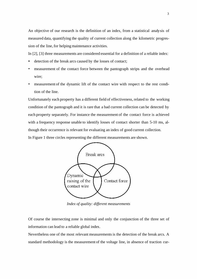
In Figure 1 three circles representing the different measurements are shown.
Index of quality: different measurements
Of course the intersecting zone is minimal and only the conjunction of the three set of
information can lead to a reliable global index.
Nevertheless one of the most relevant measurements is the detection of the break arcs. A
standard methodology is the measurement of the voltage line, in absence of traction cur-

4
rent, but the effectiveness of such method is heavily limited from the short duration of
the time available for measurements, due to the decreasing speed of the train. A different
innovative method is a visual control of the pantograph contact via a camera installed on
the top deck of the locomotive, but results are difficult to analyse and unreliable.
2 An innovative sensor: the twin phototube
Preliminary studies ([3], [4]) have shown the effectiveness of a phototube sensor for
measuring the duration of the ultraviolet emission due to electrical arcing during the
losses of contact between the pantograph and the overhead line. A second phototube
sensor [5] has been mounted on the top deck of the locomotive (the so-called twin pho-
totube), for detecting the entering break arcs and the exit break arcs. It must be high-
lighted that the proposed system is non-invasive with respect to the pantograph equip-
ment, cheap, and easy to validate in the presence of an equipotential wire connecting the
front and the rear pantograph. The output signal is binary and the voltage – on/off state
– produces square wave signals. The software package for acquisition can process and
correlate data acquired e.g. from: the twin phototube, the equipotential wire between the
front and the rear pantograph, the total current absorbed, the reference of the kilometric
progression, the speed of the train. The measurement equipment was installed on board
of an ETR500, a high-speed train of Italian Railways, with a double pantograph,
equipped with an equipotential wire, able to compensate the losses of contact with cur-
rent conduction, whenever one of the two pantographs looses the contact.
Break arc and current conduction in the equipotential wire

5
The acquisition system is controlled from a master workstation located inside the meas-
urement coach: the acquired data are available on board for an on-line analysis or for an
off-line post-elaboration. A logic scheme related to the data acquisition from the photo-
tube is drawn in Figure 3.
Measurement system
In [3] the validation of the phototube sensor by using data collected from the equipoten-
tial wire is described. As a relevant result of test runs along the railway connecting Roma
to Florence, it was verified that the repeated occurrence of arcing at the same locations
of the line on different runs reveals critical points. Therefore we supposed that the twin
phototube constitutes a reliable sensor for monitoring the status of the overhead line, for
predicting an excessive wire wear and therefore for helping maintenance activities.

6
3 High-speed test runs
Trial runs have been carried out travelling along the high-speed railway line connecting
Rome Settebagni to Orte. The measurement equipment was installed on board an
ETR500, with two symmetric pantographs ATR90. A second phototube sensor has
been set up on the top deck of the locomotive, for detecting the entering break arcs and
the exit break arcs. As a matter of fact, observed data reveal that exit break arcs are
more frequent than entering ones at high speeds. The presence of a second phototube
guarantees an effective measurement of the exit break arcs even if the train has inverted
its direction, so that the pantograph monitored changes its relative position, i.e. the
front pantograph becomes the rear one. In such a way the exit break arcs are detected
and the ‘twin phototube’ becomes a reliable sensor for a precise identification of the
losses of contact along the line. The new sensor has been validated, by comparing its
output results with data acquired by equipotential wire (EW) current measurements.
Data analysis has been performed collecting and correlating different pieces of informa-
tion. Among them the following parameters are considered crucial:
speed of the train (the quality of current collection reduces if the train speed in-
creases);
kilometric progression, for identifying precisely the position of the singular
points;
presence of tunnels, because of the overhead line parameters are varying with
the aerodynamic drags, modifying the quality of current collection.
A software package was developed in LabWindows/CVI environment for recording and
elaborating data acquired from the measurement chain. A real time software is treating
the signals (on-off) from the phototubes, separating the losses of contact into three cate-
gories, related to their duration (5 ÷ 10 ms, 10 ÷ 30 ms, > 30 ms).
Data are then organized and plotted by using a dedicated software operating in FAMOS
environment, as shown in Figure 4.

7
Example of acquisition revealing a singular break arc

8
In such figure, the upper two subplots show the duration (in ms) of break arcs detected
from the front and from the rear phototube, respectively: note that a relevant break arc
is detected.
Each loss of contact is observed from the entering or the exit arcs, function of the kilo-
metric progression of the catenary on the x-axis. The presence of break arcs is repre-
sented with vertical segments proportional to their duration (in ms). In such a way a
visual plot representing the intensity of the break arcs is drawn, so that maintenance ac-
tions can be quickly planned.
A statistical analysis is performed and histograms are plotted, related both to entering
and to exit break arcs, separately, to put into evidence distribution of the number of
break arcs per kilometre.
An index of current collection is computed, for each kilometre. It is based on the ratio of
arcing time (parts per 1000), with respect to the total time of observation.
In Figure 5 (km 28th-29th of the line connecting Rome to Orte) the electric welding ef-
fect is evidenced.

9
Example of acquisition revealing electric welding effect
10
Such effect is due to a defective sliding contact. Because of the roughness of the contact
wire and of the collector strips, mainly due to wear, the current collection is irregularly
distributed over the contact surfaces. Therefore hot spots and a micro-welding phe-
nomenon occur over the contact surfaces. If the train is running at high-speed (the higher
the speed, the more critical the effects) the welded spots are instantaneously broken off
and the contact wire further deteriorates. In such cases the wear of the collector strips
increases and continuous sparking occurs. Therefore the welding effect produces a se-
quence of continuous sparking, continuously damaging the overhead contact line with
the need of a quick maintenance. The only sensor able to detect such effect is the photo-
tube, as explained in [5]. Phototube data reveal such effect as a long (up to few kilome-
tres) series of pulses each one of a brief duration. Electric welding effect can be distin-
guished from singular break arcs, filtering raw data with a moving average along few
kilometres of acquisitions. To verify electric welding effect, test runs have been repeated
along the same line at different speeds. Furthermore such effect has been correlated with
the total traction current and with the average temperature of the strips. An example of
such analysis is shown in Figure 6, where acquisition at different four speeds are shown.
The x-axis is representing the kilometric progression (in km) from km 20 to km 60. Each
acquisition shows the total current (in kA) as the upper plot, the average temperature of
the strip (in °C) as the medium plot and the averaged break arcs from the twin photo-
tube as the lower plot.

11
Electric welding effect: representation with filtered data
4 Checking of the contact line
After an accurate analysis of the phototube data, a visual inspection was performed for
checking precisely the condition of the overhead contact line in order to verify the
anomalous situations revealed from the twin phototube sensor. Inspections were per-
formed at night, in cooperation with RFI maintenance centre, by using a trolley
equipped for catenaries checking. At km 29.5 of the line Rome- Orte, inside a tunnel
named Villa Croce, phototubes acquisitions detected a relevant break arc, as shown in
Figure 4: such anomaly was verified in different test runs at different speeds. The prob-

12
lem at hand was to discover the physical causes of such singularity. From inspections
the problem was solved: a lower clamp of a dropper (see Figure 7 showing the photo of
a similar type of dropper) was disconnected.
Dropper inside the tunnel
The free clamp of the dropper caused an impact with the pantograph heads each time
the train was passing, inducing break arcs. This anomaly was removed with a quick in-
tervention of the maintenance personnel, preventing further damages due to a possible
hung up of the clamp to the pantograph head.
A different analysis was performed in the more complex case of electric welding effect.
In such case the line between km 25 and km 30 was inspected. In Figures 8, 9, 10 differ-
ent grades of roughness of the lines are shown.

13
Copper contact line with Copper contact line with Copper contact line with
minimal roughness mean roughness high roughness
They all are examples of surfaces capable of maintaining a correct current collection in
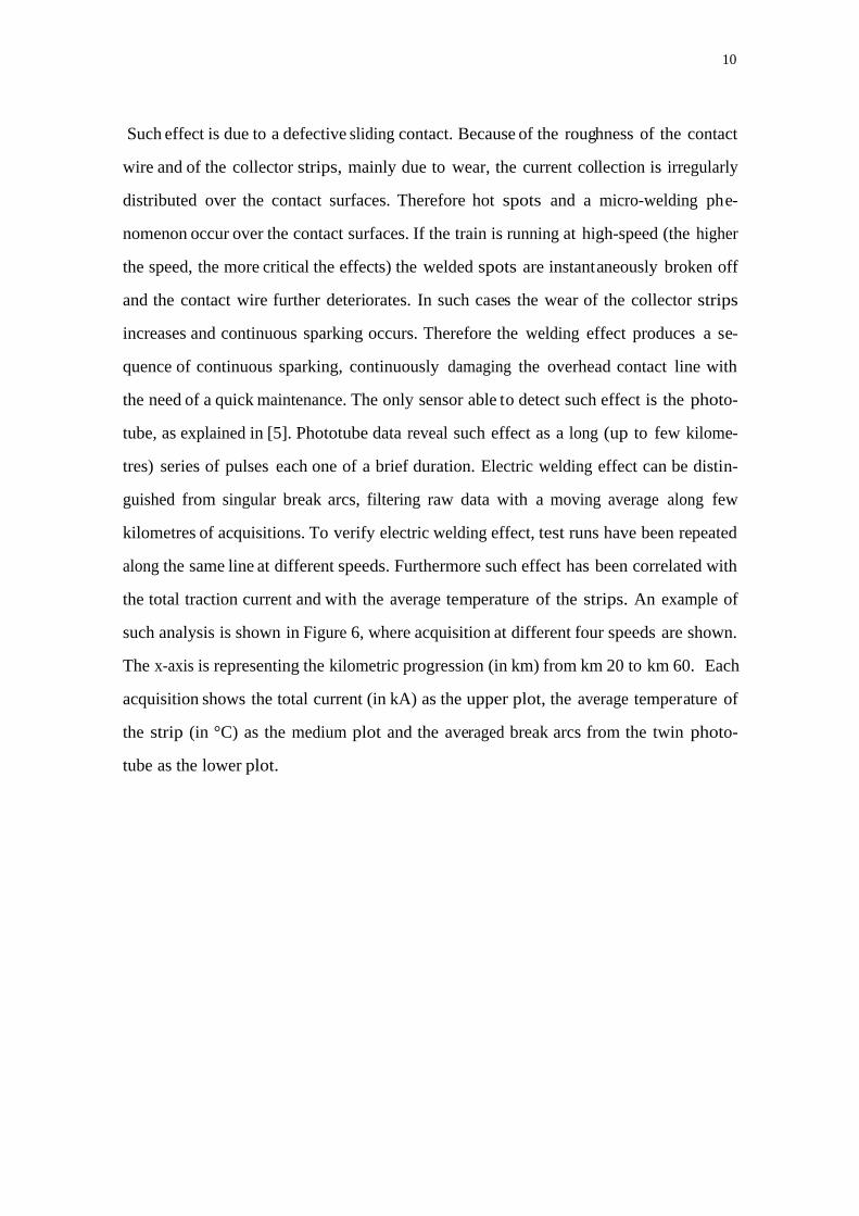
case of a sliding contact between copper materials. Figures 11 and 12 show the worn
surfaces of the contact line in the presence of electric welding effect.
Copper contact line with electric welding effect
14
Copper contact line with electric welding effect
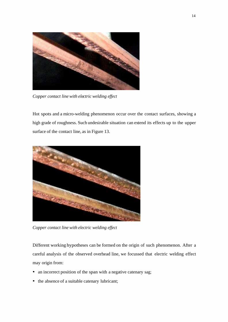
Hot spots and a micro-welding phenomenon occur over the contact surfaces, showing a
high grade of roughness. Such undesirable situation can extend its effects up to the upper
surface of the contact line, as in Figure 13.
Copper contact line with electric welding effect
Different working hypotheses can be formed on the origin of such phenomenon. After a
careful analysis of the observed overhead line, we focussed that electric welding effect
may origin from:
an incorrect position of the span with a negative catenary sag;
the absence of a suitable catenary lubricant;

15
the passage of pantographs with too hard contact strip materials.
Preventive actions are therefore planned for avoiding the electric welding effect and re-
ducing the worn of the line: an adjustment of the position of the span, controlling the
supporting droppers and a lubrication of the catenary.
5 Conclusions
It was checked that an analysis of data collected from the twin phototube sensor reveals
critical points of the overhead line and constitutes a reliable information for predicting an
excessive wire wear and for helping quick maintenance activities. Advantages of the sys-
tem proposed can be summarized as:
1. quick detection of singular points of the overhead line from the presence of repeated
break arcs for different test runs;
2. quick detection of long deteriorations of the overhead line in the presence of the elec-
tric welding effect;
3. definition of an index for evaluating the quality of the current collection. Nowadays
standard norms for interoperability between different European railways are under
development, in order to create a European high speed rail network. A primary objec-
tive for a common network is to define and guarantee an index of quality of the con-
tact between pantograph and catenary;
4. preventive actions can be planned for avoiding damages to the line and for improving
the regularity and the safety of the train traffic, especially in high speed running lines.
Acknowledgements
The financial support of MURST (Italian Ministry of University and Scientific Re-
search), ‘Innovative Controls in High Speed Transport Systems’ Project is gratefully
acknowledged.

16
6 References
1. A.Fumi, P.Giorgi, S.Panza, A.Rossi: “A new special trolley equipped for automaticchecking of contact lines,” Proceeding of the World Congress on Railway Research,vol. C, pp.15-23, Firenze, 16-19 nov. 1997.
2. M.Papi, E.Mingozzi, A.G.Violi, O.Bruno, A.Landi, L.Sani: “La captazione dicorrente e l’interazione pantografo-catenaria. Parte II: Metodologie Metodologieinnovative non invasive per il rilevamento della qualità della captazione nellecatenarie a 3 KV,” Ingegneria Ferroviaria, pp. 233-244, maggio 2000.
3. O.Bruno, A.Landi, L.Sani, M. Papi, “Phototube sensor for monitoring the quality ofcurrent collection on overhead electrified railways,” Proc. Inst. Mech. Engrs.IMechE, Part F, in press, 2001.
4. A. Balestrino, O.Bruno, A.Landi, L.Sani, M. Papi, A.G. Violi, “Phototube sensorfor active pantograph,” CD-ROM of the World Congress on Railway Research, pp.1-7, Tokio, 19-23 oct. 1999.
5. O.Bruno, A.Landi, M.Papi, L.Sani, A.G.Violi: “Pantograph-catenary monitoring:correlation between breack arcs and harmonics in the traction currents,” CD-ROMof the World Congress on Railway Research, Koln, 19-23 oct. 2001.