electrical and i&c codes and inspection690 - cable systems clause 5. conductor sizing • the...
TRANSCRIPT
ELECTRICAL AND I&CCODES AND INSPECTION
1Numark Associates, Inc.
Day 6
DAY 6
Sessions:12 Installation Standards
13 Inspection and Testing Standards
2Numark Associates, Inc.
g
14 Operation, Maintenance and Surveillance Standards
Student Activity: Electrical Component vs. IEEE Standards Matrix
Session 12
3Numark Associates, Inc.
Installation Standards

12. Installation Standards Objectives
• Identify the major installation standards
P id l i f th
4Numark Associates, Inc.
• Provide a general overview of the purpose of these standards
• Discuss how these standards relate to new reactor inspection

12. Installation Standards
• 336 - Power, instrumentation, control equipment
5Numark Associates, Inc.
• 384 - Independence
• 484 - Battery installation
12. Installation Standards
• 576 - Installation, termination, and testing of Cables
628 R
6Numark Associates, Inc.
• 628 - Raceways
• 665 - Grounding power systems
• 690 - Cable systems
12. Installation Standards
• 1050 - Grounding I&C systems
• 1185 - Cable installation methods
7Numark Associates, Inc.
1185 Cable installation methods
• 1210 - Cable lubrication
336 - Power, Instrumentation, Control Equipment
• Covers pre-installation, installation, inspection, and testing
A li bl t i iti l t ti
8Numark Associates, Inc.
• Applicable to initial construction, modification, and maintenance activities
• Does not apply to periodic testing
336 - Power, Instrumentation, Control Equipment
4. General considerations for initial construction, modification, and maintenance
5 Pre-installation constructability review
9Numark Associates, Inc.
5. Pre installation constructability review
6. Installation/Construction
7. Testing

336 - Power and I&C EquipmentClause 5. Constructability Review
• Approved-for-construction drawings• Installation specifications and procedures• Identification of materials and equipment• Protective measures for storage and
10Numark Associates, Inc.
ghandling
• Examination of materials and equipment for damage
• Qualification reports and documents reviewed and approved

336 - Power and I&C EquipmentClause 6. Installation/Construction
6.1 Equipment placement
6.2 Engineering procedures and specifications
11Numark Associates, Inc.
6.3 Verification during installation
6.4 Post-installation inspections
6.5 Inspections of temporary conditions
384 - Independence
• The independence requirements of the circuits and equipment associated with Class 1E systems
12Numark Associates, Inc.
• Criteria for independence that can be achieved by physical separation and electrical isolation of circuits and equipment
384 - Independence
4. General independence criteria
5. Specific separation criteria
13Numark Associates, Inc.
p p
6. Specific electrical isolation criteria
384 – IndependenceClause 4. General Independence Criteria
4.1 Required independence
4.2 Methods of achieving independence
4.3 Equipment and circuits requiring
14Numark Associates, Inc.
independence
4.4 Compatibility with supporting features
4.5 Associated circuits
4.6 Non-class 1E circuits -General criteria

384 – Independence Clause 4. General Independence Criteria
4.7 Mechanical systems
4.8 Structures and equipment
4.9 Fire protection systems
15Numark Associates, Inc.
4.10 Fire
4.11 Electromagnetic interference/radio frequency interference (EMI/RFI)
384 – IndependenceClause 5. Specific Separation Criteria
5.1 Cables and raceways
5.2 Standby power supply
16Numark Associates, Inc.
5.3 DC system
5.4 Distribution system
5.5 Containment electrical penetrations

384 – IndependenceClause 5. Specific Separation Criteria
5.6 Control switchboards
5.7 Instrumentation cabinets
5 8 Sensors
17Numark Associates, Inc.
5.8 Sensors
5.9 Actuated equipment
5.10 EMI/RFI
384 – IndependenceClause 6. Specific Electrical Isolation Criteria
6.1 Power circuits
6 2 Instrumentation and control
18Numark Associates, Inc.
6.2 Instrumentation and control circuits
484 - Battery Installation
• This standard provides recommended design practices and procedures for storage, location, mounting, ventilation, instrumentation, pre-assembly,
19Numark Associates, Inc.
assembly, and charging of vented lead-acid batteries.
• Required safety practices are also included.
484 - Battery Installation
4. Safety
5. Installation Design Criteria
20Numark Associates, Inc.
6. Installation Procedures
7. Records

484 - Battery Installation Clause 4. Safety
4.1 Protective equipment
21Numark Associates, Inc.
4.2 Precautions
484 - Battery InstallationClause 5. Installation Design
5.1 Location
5.2 Mounting
5 3 Seismic
22Numark Associates, Inc.
5.3 Seismic
5.4 Ventilation
5.5 Instrumentation and alarms
484 - Battery InstallationClause 6. Installation Procedures
6.1 Receiving and storage
6.2 Assembly
23Numark Associates, Inc.
6.3 Freshening charge, data collection, and testing
6.4 Connection to dc system
484 - Battery Installation
Clause 7. Records
• Receiving inspection data and conditions of charge
• Initial resistance values of the intercell connections
• Individual cell specific gravities, voltage measurements, electrolyte levels and temperatures
24Numark Associates, Inc.
electrolyte levels and temperatures
• Acceptance test data
• Cell serial number, manufacture date, and lot number

576 - Installation, Termination, andTesting of Cables
• Provides a guide for installing, splicing, terminating, and field proof testing of cable systems
25Numark Associates, Inc.
• It is not intended to be a design document.
• One of the most valuable installation standards
576 - Installation, Termination and Testing of Cables
4. Pulling Tensions
5 Sidewall Pressure
26Numark Associates, Inc.
5. Sidewall Pressure
6. Jamming

576 - Installation, Termination and Testing of Cables
7. Recommended Bending Radii for Cables
27Numark Associates, Inc.
8. Minimum Installation Temperature
12. Pulling Lubricants

576 - Installation, Termination andTesting of Cables
9. Direct Burial
10 Cable Tray Installation
28Numark Associates, Inc.
10. Cable Tray Installation
11. Aerial Cable Installation
576 - Installation, Termination andTesting of Cables
13. Splicing
14 Terminating
29Numark Associates, Inc.
14. Terminating
15. Electrical Connections
16. Field Acceptance Testing
576 – Installation of Cables
Clause 4. Pulling Tensions
4.1 Maximum pulling tension on cable4.2 Maximum pulling lengths4.3 Small conductor cables4 4 Pulling tension requirements in duct
30Numark Associates, Inc.
4.4 Pulling tension requirements in duct and conduit
4.5 Check list prior to pulling cable4.6 Methods of gripping cables for
pulling
576 – Installation of Cables Clause 5. Sidewall Pressure
5.1 Sidewall pressure limitations
5 2 Weight correction factor
31Numark Associates, Inc.
5.2 Weight correction factor calculations

576 – Installation of Cables Clause 6. Jamming
6.1 Computation of ratio
6 2 Jam ratio
32Numark Associates, Inc.
6.2 Jam ratio
576 – Installation of CablesClause 7. Minimum Bending Radius
7.1 Cables without metallic shielding or armor
7 2 Cables with metallic armor
33Numark Associates, Inc.
7.2 Cables with metallic armor
7.3 Shielded cables
7.4 Portable cables

576 – Installation of CablesClause 8. Installation Temperature
Table 7, Minimum Installation Temperatures
34Numark Associates, Inc.
8.1 After installation
8.2 Storage prior to installation

576 – Installation of CablesClause 8. Table 7
Cable Insulation or Jacket Material
Minimum Insulation Temperature
PVC -10 oC/14 oF
35Numark Associates, Inc.
PPVP, CSPE, CPE -20 oC/-4 oF
XLPE, PE, EPR -40 oC/-40 oF

576 – Installation of CablesClause 12. Pulling Lubricants
• Compatibility with the cable jacket material
E t diti f t t
36Numark Associates, Inc.
• Extreme conditions of temperature
• Impact on the flame resistance of the cable

576 – Installation of Cables Clauses 9, 10, and 11
9. Direct Burial
10 Cable Tray Installation
37Numark Associates, Inc.
10. Cable Tray Installation
11. Aerial Cable Installation
576 - Termination of CablesClause 13. Splicing
13.1 Solid dielectric insulated cable
38Numark Associates, Inc.
13.2 Lead sheathed cable
576 - Termination of Cables Clause 14. Terminating
14.1 Cable preparation
39Numark Associates, Inc.
14.2 Installation of terminations
576 - Testing of Cables Clause 15. Electrical Connections
15.1 Connector types
15.2 Contact resistance
40Numark Associates, Inc.
15.3 Clamp connectors
15.4 Cable connection to bus bar
576 - Testing of Cables Clause 15. Electrical Connections
15.5 Thermal expansion
15.6 Joint compounds for aluminum
41Numark Associates, Inc.
15.6 Joint compounds for aluminum connections
15.7 Connectors for aluminum
15.8 Connection procedures
576 - Testing of Cables Clause 16. Field Acceptance Testing
16.1 Advantages of high voltage dc acceptance testing
42Numark Associates, Inc.
16.2 Installation acceptance test voltages
16.3 Interpretation of test results

576 - Testing of CablesClause 16. Field Testing
• IEEE Std 400 Overview
– 400.1 Direct current (DC)400 2 Very low frequency (VLF)
43Numark Associates, Inc.
– 400.2 Very low frequency (VLF)– 400.3 Partial discharge (PD)– 400.4 Dissipation factor (DF)– 400.5 Power frequency (PF)– 400.6 Oscillating wave (OW)
628 - Class 1E Raceways
• Provides criteria for the minimum requirements in the design, installation, and qualification of raceway systems
44Numark Associates, Inc.
• Prescribes methods for the structural qualification of raceway systems

628 - Class 1E Raceways
4. Design
5. Qualification Methods
45Numark Associates, Inc.
6. Installation
7. Documentation
628 - Class 1E Raceways Clause 4. Design
4.1 General
4.2 Separation criteria
46Numark Associates, Inc.
4.3 Grounding
4.4 Raceway identification
4.5 Raceway system protection

628 - Class 1E RacewaysClause 4. Design
4.6 Environmental considerations
4.7 Materials
47Numark Associates, Inc.
4.8 Metallic raceway system finishes
4.9 Raceway system requirements
4.10 Structural design criteria

628 - Class 1E RacewaysClause 5. Qualification Methods
5.1 Analysis
5.2 Dynamic testing
5 3 Combined anal sis and testing
48Numark Associates, Inc.
5.3 Combined analysis and testing
5.4 Seismic-experience-based qualification
5.5 Acceptance criteria
628 - Class 1E RacewaysClause 6. Installation
6.1 Packaging, shipping, receiving, storage, and handling
49Numark Associates, Inc.
6.2 Installation of raceway systems
628 - Class 1E Raceways Clause 7. Documentation
7.1 Design activities
7.2 Raceway system components
50Numark Associates, Inc.
7.2 Raceway system components
7.3 Construction activities
7.4 Document collection, storage, and maintenance

665 - Grounding Power Systems
• Generally accepted utility grounding practices for personnel safety and equipment protection
• Guide for the design of generating
51Numark Associates, Inc.
g g gstation grounding structures, systems, and components
• Interconnection of the station and substation grounding systems

665 - Grounding Power Systems
4. Design Objectives
5. Detailed Design Considerations
52Numark Associates, Inc.
g

665 - Grounding Power SystemsClause 4. Design Objectives
4.1 Neutral ground, equipment ground, and safety ground
4.2 Station grounding system
53Numark Associates, Inc.
g g y
4.3 Preventing the transfer of high ground voltages
4.4 Design objectives

665 - Grounding Power SystemsClause 5. Detailed Design
5.1 Grounding principles
5.2 Ground grid design
54Numark Associates, Inc.
5.3 Generator and isolated phase bus grounding
5.4 Grounding of buildings, fences, and structures
665 - Grounding Power SystemsClause 5. Detailed Design
5.5 Grounding of station auxiliaries
5.6 Lightning protection forstructures
55Numark Associates, Inc.
structures
5.7 Grounding of buried structures
5.8 Sizing of grounding conductors

665 - Grounding Power SystemsInformative Annexes
A Determination of the k factor
B Corrosion
56Numark Associates, Inc.
C Division of current for small interior grids
690 - Cable Systems
• Design and installation of safety-related electrical cable systems
57Numark Associates, Inc.
• Includes associated circuits
690 - Cable Systems
4. Cable, Field Splice, and Connection Qualification
5. Conductor Sizing6 Electrical Segregation
58Numark Associates, Inc.
6. Electrical Segregation7. Separation and Identification8. Shielding and Shield Grounding9. Cable-Penetration Fire Stops, Fire
Breaks, and System Enclosures
690 - Cable Systems
10. Fire-Detection Systems
11. Fire-Extinguishing Systems
12 Handling and Installation
59Numark Associates, Inc.
12. Handling and Installation
13. Acceptance Testing of Installed Cables
14. Documentation
690 - Cable SystemsClause 5. Conductor Sizing
• The minimum ambient temperatures used in calculating cable ampacities shall be 30°C for buried installations and 40°C for exposed installations.
• Conductor size shall be selected for normal, emergency overload, and short-circuit current without exceeding rated temperature of the insulation at the maximum ambient temperature.
60Numark Associates, Inc.
temperature.
• Conductor size shall be selected for the limiting raceway condition.
• Conductor size shall consider voltage drop, shield current, and mechanical strength.
• Cable ampacity shall consider appropriate de-ratings due to installation conditions.

690 - Cable SystemsClause 6. Electrical Segregation
6.1 Cable Classifications
6 2 Requirements
61Numark Associates, Inc.
6.2 Requirements

690 - Cable SystemsClause 7. Separation and Identification
• Clause 7 Invokes IEEE Std 384 for the Separation and Identification Requirements
62Numark Associates, Inc.
Requirements
690 - Cable SystemsClause 8. Shielding and Shield Grounding
8.1 Medium-voltage power cable
8 2 Instrumentation cable
63Numark Associates, Inc.
8.2 Instrumentation cable
690 - Cable Systems Clause 9. Cable-Penetration Fire Stops and Fire Breaks
9.1 General requirements
9.2 Cable-penetration fire stop requirements
64Numark Associates, Inc.
9.3 Cable tray fire break requirements
9.4 Cable-system enclosure requirements

690 - Cable Systems Clauses 10 and 11
10. Fire-Detection Systems
11 Fire Extinguishing Systems
65Numark Associates, Inc.
11. Fire-Extinguishing Systems
690 - Cable SystemsClause 12. Handling and Installation
12.1 General requirements
12.2 Storage requirements
12 3 Cable-installation requirements
66Numark Associates, Inc.
12.3 Cable installation requirements
12.4 Raceway - cable-fill requirements
12.5 Requirements for supporting cables in vertical runs
690 - Cable Systems Clauses 13 and 14
13. Acceptance Testing of Installed Cables
67Numark Associates, Inc.
14. Documentation
1050 - Grounding I&C Systems
• Suitable level of protection for personnel and equipment, and
68Numark Associates, Inc.
• Suitable electric noise immunity for signal ground references in generating stations

1050 - Grounding I&C Systems
4. Electrical Noise Minimization
5. I&C System Grounding
69Numark Associates, Inc.
6. Signal Cable Shield Grounding
7. Testing
1050 - Grounding I&C Systems
Clause 4. Electrical Noise Minimization
4.1 Typical noise sources and their characteristics
70Numark Associates, Inc.
4.2 Noise-coupling methods
4.3 Techniques for electrical noise minimization

1050 - Grounding I&C SystemsClause 5. I&C System Grounding
5.1 Grounding philosophy5.2 Types of signal ground systems5.3 Separation criteria for circuits5 4 I&C system power considerations
71Numark Associates, Inc.
5.4 I&C system power considerations5.5 Surge protection considerations5.6 Other grounding considerations5.7 Generating station EMI environment

1050 - Grounding I&C SystemsClause 6. Signal Cable Shield Grounding
6.1 Cable shield requirements6.2 Analysis of shield grounding
practices6.3 Other cable shielding considerations6 4 Comparison of shielding
72Numark Associates, Inc.
6.4 Comparison of shielding effectiveness
6.5 Common practices in shielding cables for distributed control and PLC circuits
6.6 Central distribution frame grounding
1050 - Grounding I&C Systems Clause 7. Testing
7.1 General7.2 Sources of conductive ground loops7.3 Ground loop prevention and
detection
73Numark Associates, Inc.
detection7.4 Testing for ground loops7.5 Signal ground system integrity7.6 Maintenance of the signal ground
1050 - Grounding I&C Systems
Annex C - Examples of I&C Grounding Methods
74Numark Associates, Inc.
1185 - Cable Installation Methods
• The purpose of this recommended practice is to avoid potential wire or cable damage during the installation and testing process
75Numark Associates, Inc.
installation and testing process.
1185 - Cable Installation Methods
4. Conduit-Cable Pulling Charts
5. Cable Pulling Attachment Methods
6. Pull Rope Selection
76Numark Associates, Inc.
7. Lubrication Techniques
8. Tension Limiting Methods
9. Cable Pullbys
10. Pullbacks
1185 - Cable Installation MethodsClause 4. Conduit-Cable Pulling
4.1 General4.2 Cable types and raceway
configurations4.3 Use of conduit-cable pulling charts
77Numark Associates, Inc.
4.4 Bend correction adjustment4.5 Examples4.6 Methodology4.7 Pulling tension
1185 - Cable Installation MethodsClause 5. Cable Pull Attachments
5.1 General5.2 Basket-type pulling grips5.3 Compression-type pulling eyes
78Numark Associates, Inc.
p yp p g y5.4 Wedge-type pulling eyes5.5 Mare’s tails5.6 Swivels

1185 - Cable Installation MethodsClause 6. Pull Rope Selection
6.1 General
6.2 Guidelines for pull rope selection
79Numark Associates, Inc.
selection
6.3 Precautions

1185 - Cable Installation MethodsClause 7. Lubrication Techniques
7.1 When to use lubricant7.2 Lubricant quantity7.3 Methods of lubricating conduit
t
80Numark Associates, Inc.
systems7.4 Cable jacket lubrication7.5 Lubrication procedure7.6 Clean up and safety
1185 - Cable Installation MethodsClause 8. Tension Limiting Methods
8.2 Limiting size of pulling crew
8 3 Dynamometer
81Numark Associates, Inc.
8.3 Dynamometer
8.4 Break link
1185 - Cable Installation MethodsClause 9. Cable Pullbys
9.1 General
9.2 Conditions for potentially
82Numark Associates, Inc.
successful pullbys
9.3 Installation practices
9.4 Post-pullby testing

1185 - Cable Installation Methods
Clause 10. Pullbacks
10.1 General
10 2 Cable inspection
83Numark Associates, Inc.
10.2 Cable inspection
10.3 Installation practices

1185 - Cable Installation MethodsNormative Annexes
A. Examples - Use of conduit-cable pulling charts
B. Methodology - Conduit-cable pulling charts
84Numark Associates, Inc.
charts
C. Bend correction factor - Conduit-cable pulling charts
1210 - Compatibility of Cable-Pulling Lubricants with Cable
• Cable-pulling lubricants are used to lower the friction on cable.
85Numark Associates, Inc.
• Lubricants should not negatively interact with the cables they lubricate.

1210 - Compatibility of Cable-Pulling Lubricants with Cable
3. Physical property effects
86Numark Associates, Inc.
4. Electrical property effects
5. Testing and test methods

1210 - Pulling LubricantsClause 3. Physical Property Effects
3.1 General
87Numark Associates, Inc.
3.2 Lubricant on cable jacket
1210 - Pulling LubricantsClause 4. Electrical Property Effects
4.2 Semiconducting jackets and shields
4.3 Stability of lubricant on semiconductors
88Numark Associates, Inc.
4.4 Final high-temperature volume resistivity test
4.5 Lubricant on thermoplastic insulation
4.6 Lubricant on thermoset insulation
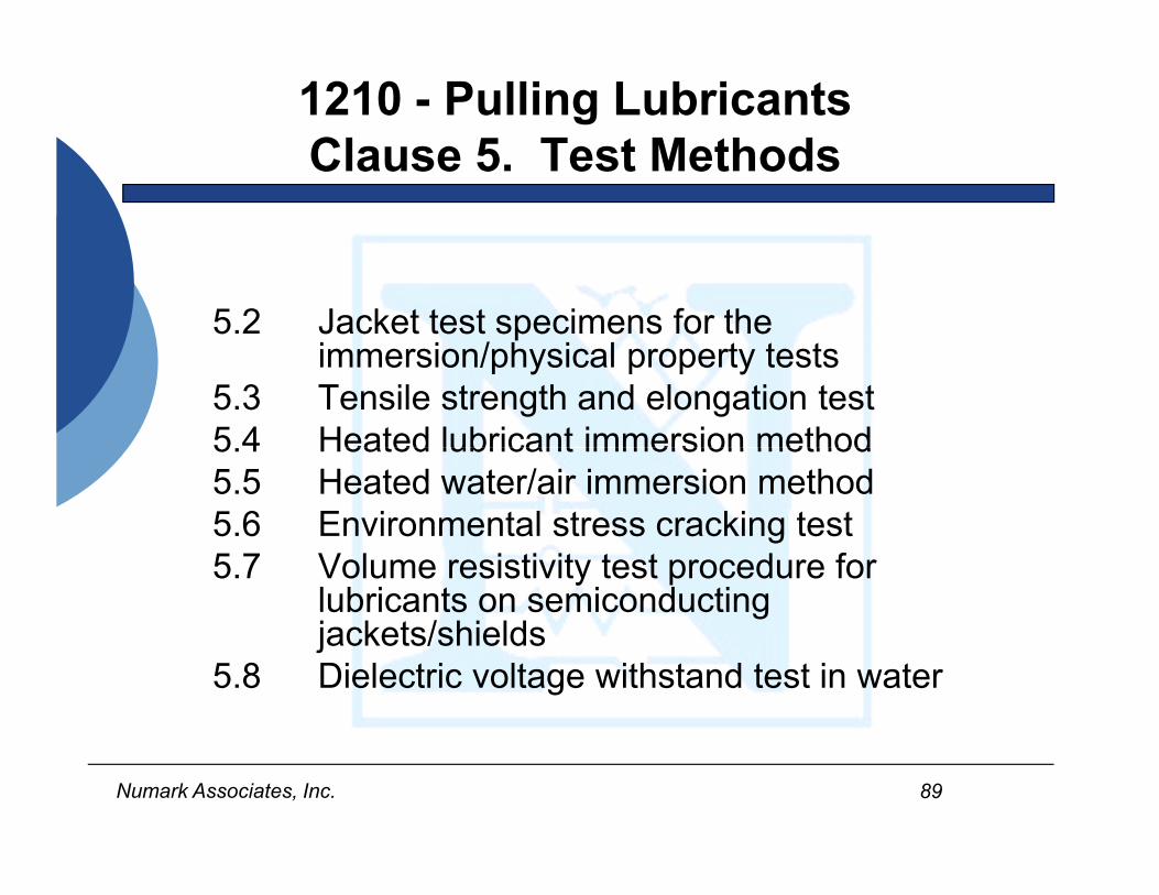
1210 - Pulling LubricantsClause 5. Test Methods
5.2 Jacket test specimens for the immersion/physical property tests
5.3 Tensile strength and elongation test5 4 Heated lubricant immersion method
89Numark Associates, Inc.
5.4 Heated lubricant immersion method5.5 Heated water/air immersion method5.6 Environmental stress cracking test5.7 Volume resistivity test procedure for
lubricants on semiconducting jackets/shields
5.8 Dielectric voltage withstand test in water
12. Installation Standards Objectives Review
• Identified the major installation standards
• Provided a general overview of the purpose of these standards
90Numark Associates, Inc.
purpose of these standards
• Discussed how these standards relate to new reactor inspection by identifying and discussing their major clauses
12. Installation Standards Out of Scope
• 381 - Class lE Modules OOS
• 634 - Cable Penetration Fire Stops
91Numark Associates, Inc.
OOS
• 1120 - Guide to Considerations for Submarine Cable Installation OOS
Session 13
92Numark Associates, Inc.
Inspection and Testing
Standards

13. Inspection and Testing Objectives
• Identify the major inspection and testing standards
• Provide a general overview of the
93Numark Associates, Inc.
Provide a general overview of the purpose of these standards
• Discuss how these standards relate to new reactor inspection

13. Inspection and Testing Standards
• 336 - Guide for Installation, Inspection, and Testing for Class 1E Power, Instrumentation, and Control Equipment
94Numark Associates, Inc.
Control Equipment
• 1050 - I&C Grounding (Testing)
13. Inspection and Testing Standards
• 387 - Diesels
• 450 - Batteries (Testing)
95Numark Associates, Inc.
• 944 - UPS
• 1458 - Molded Case Circuit Breakers
13. Inspection and Testing Standards
• 48 - Initial Testing of MV Cable Terminations
• 400 Field Testing of Shielded Power Cables
576 I t ll ti T i ti d T ti f
96Numark Associates, Inc.
• 576 Installation, Terminating and Testing of Power Cables
• 690 Cable Systems (Testing)
• 1185 Cable Pullbys (Testing)
336 - Power, Instrumentation, Control Equipment
• Pre-installation, installation, inspection, and testing of Class 1E power, instrumentation, and control equipment and systems
97Numark Associates, Inc.
y
• Applicable to initial construction, modification and maintenance activities
336 - Power, Instrumentation, Control Equipment
4. General Considerations for Initial Construction, Modification, and Maintenance
98Numark Associates, Inc.
5. Pre-Installation Constructability Review
6. Installation/Construction
7. Testing

336 - Power, Instrumentation, Control Equipment Clause 7. Testing
• 7.1 General
• 7 2 Material source testing
99Numark Associates, Inc.
7.2 Material source testing

336 - Power, Instrumentation, Control Equipment Clause 7. Testing
7.3 Electrical Tests
• Correct wiring
• EMI/RFI compatibility
100Numark Associates, Inc.
• Functional tests
• Insulation resistance.
• Dielectric strength
336 - Power, Instrumentation, Control Equipment Clause 7. Testing
7.4 Physical and Chemical Tests
• Chemical analysis of fluids
101Numark Associates, Inc.
• Radiation Testing
336 - Power, Instrumentation, Control Equipment Clause 7. Testing
7.5 Mechanical Tests
• Flow and pressure tests on instrument connections
102Numark Associates, Inc.
• Flow tests on required ventilation and cooling components
336 - Power, Instrumentation, Control Equipment Clause 7. Testing
7.6 Equipment functional tests
7 7 System tests
103Numark Associates, Inc.
7.7 System tests
7.8 Post-modification/ maintenance testing

1050 - I&C Grounding (Testing)
• I&C equipment grounding methods for
104Numark Associates, Inc.
– Protection for personnel and equipment
– Noise immunity for signal ground
1050 - I&C Grounding (Testing)
4. Design considerations for electrical noise minimization
5 I&C system grounding
105Numark Associates, Inc.
5. I&C system grounding
6. Signal cable shield grounding
7. Testing

1050 - Grounding I&C SystemsClause 7. Testing
7.1 General
7.2 Sources of conductive ground loops
7 3 Ground loop prevention and
106Numark Associates, Inc.
7.3 Ground loop prevention and detection
7.4 Testing for ground loops
7.5 Signal ground system integrity
7.6 Maintenance of the signal ground

387 - Diesel Generators
• Application and testing of diesel-generator units
107Numark Associates, Inc.
• Covers site testing

387 - Diesel Generators Testing
• Factory
• Qualification
108Numark Associates, Inc.
• Site Acceptance
• Periodic Surveillance
387 - Diesel GeneratorsClause 7. Site Testing
7.1 Testing
7.2 Site acceptance testing
7.3 Pre-operational testing
109Numark Associates, Inc.
7.4 Periodic testing
7.5 Test descriptions
7.6 Records

944 – Application and Testing of UPS
• Application and performance requirements for a UPS system
110Numark Associates, Inc.
• Requirements for design, procurement, and testing
944 – Application and Testing of UPS
4. Service Conditions
5. Design Application Requirements
111Numark Associates, Inc.
q
6. Procurement Document Requirements
7. Testing Requirements

944 – Application and Testing of UPS Clause 7. Testing
7.1 General
7.2 Functional Unit Tests
7.3 UPS Tests
112Numark Associates, Inc.
7.4 Test Specifications
1458 – Molded Case Circuit Breakers
3. MCCB Basics
4. MCCB Safety Considerations
5. Selection of MCCBs
113Numark Associates, Inc.
6. Estimated Available Fault Current
7. Simplified Method to Calculate Fault Current
8. Field Testing of MCCBs
1458 – MCCBs Clause 8. Field Testing
8.1 Rated current hold in test8.2 Exposed face and lug
temperature8.3 Mechanical operation tests
114Numark Associates, Inc.
8.3 Mechanical operation tests8.4 Insulation resistance test8.5 Individual pole resistance test

CABLES
115Numark Associates, Inc.

48 - Initial Testing of MV Cable Terminations
• Indoor and outdoor AC cable terminations
• Laminated insulation rated 2.5 kV
116Numark Associates, Inc.
Laminated insulation rated 2.5 kV through 765 kV
• Extruded insulation rated 2.5 kV through 500 kV

48 - Initial Testing of MV Cable Terminations
4. Service Conditions
5. Rating
6. Product Markings
7 T t R i t
117Numark Associates, Inc.
7. Test Requirements
8. Test Procedures
9. Application Guide
10. Suggested Environmental Tests
48 - Initial Testing of MV Cable Terminations Clause 7. Test Requirements
7.1 Design tests
7 2 Routine tests
118Numark Associates, Inc.
7.2 Routine tests
7.3 Installed field tests
48 - Initial Testing of MV Cable Terminations Clause 8. Test Procedures
8.1 Preparation of test specimen8.2 Standard test conditions8.3 Correction factors
119Numark Associates, Inc.
8.4 Design tests8.5 Routine tests8.6 Dielectric field tests

400 - Field Testing of ShieldedPower Cables
• This guide lists various field test methods – presently available – under development
• Field tests on insulated, shielded power cable
120Numark Associates, Inc.
psystems rated 5 kV through 500 kV
• Consider the performance of the entire cable system, including joints, terminations, and associated equipment
400 - Field Testing of Shielded Power Cables
400.1 DC High Potential
400 2 Very Low Frequency
121Numark Associates, Inc.
400.2 Very Low Frequency
400.3 Partial Discharge
576 - Installation, Terminating and Testing of Power Cables
• A guide for installing, splicing, terminating, and field proof testing of cable systems in industrial and
122Numark Associates, Inc.
ycommercial applications is provided.
576 - Installation, Terminating, and Testing of Power Cables
Clause 16. Field Acceptance Testing
16.1 Advantages of high voltage dc acceptance testing
123Numark Associates, Inc.
16.2 Installation acceptance test voltages
16.3 Interpretation of test results
690 Cable Systems (Testing)
• Design and installation of safety related electrical cable systems
124Numark Associates, Inc.
690 - Cable Systems Clause 13
Acceptance Testing of Installed Cables
• Medium voltage power cables should be hi-pot tested prior to equipment connection.
125Numark Associates, Inc.
• VLF can be performed in lieu of high-potential testing if trending of service aged cables is desired.
• Low-voltage cables shall be either IR tested prior to connecting cables.
1185 - Cable Installation Methods
Sub Clause 9.4 Post-Pullby Testing
• Test Per IEEE 690 on both
Initial Cables
126Numark Associates, Inc.
– Initial Cables
– Recently Pulled Cables
13. Inspection and Testing Objectives Review
• Identified the major Inspection and Testing Standards
• Provided a General Overview of the Purpose of these Standards
127Numark Associates, Inc.
of these Standards
• Discussed how these Standards relate to New Reactor Inspection by identifying and discussing their major Clauses.
13. Inspection and Testing Standards Out of Scope
• 415 - Preoperational Testing Program - Class 1E Systems OOS
128Numark Associates, Inc.
g y
Session 14
129Numark Associates, Inc.
Operation, Maintenance, and Surveillance Standards

14. Operation, Maintenance and Surveillance Standards Objectives
• Identify the major operation, maintenance and surveillance standards
• Provide a general overview of the purpose of these standards
130Numark Associates, Inc.
p p
• Discuss how these standards relate to new reactor inspection by identifying and discussing their major clauses
14. Operation, Maintenance and Surveillance Standards
• 400 - Cables
• 450 Batteries
131Numark Associates, Inc.
• 450 - Batteries
• 498 - Measuring and Test Equipment

14. Operation, Maintenance and Surveillance Standards
• 749/387 - Diesels
• 934 - Replacement Parts
132Numark Associates, Inc.
934 Replacement Parts
• 1205 - Assessing Aging Effects

400 – Cables
• This guide lists the various field test methods that are presently available or under development to perform field tests on insulated, shielded power cable systems rated 5 kV through 500 kV
133Numark Associates, Inc.
systems rated 5 kV through 500 kV.
• Consideration should be given to the performance of the entire cable system, including joints, terminations, and associated equipment.
450 - Batteries
• Provides maintenance, test schedules, and testing procedures
134Numark Associates, Inc.
• Guidance to determine when batteries should be replaced
450 - Batteries
4. Safety5. Maintenance6 Test Schedule
135Numark Associates, Inc.
6. Test Schedule7. Procedure for Battery Tests8. Battery Replacement Criteria
450 - Batteries Clause 5. Maintenance
5.1 General
5.2 Inspections
136Numark Associates, Inc.
5.3 Corrective actions
5.4 State of charge
450 - Batteries Clause 6. Test Schedule
6.1 Acceptance
6.2 Performance
137Numark Associates, Inc.
6.3 Service
6.4 Modified performance test
498 - Measuring and Test Equipment
• Provides requirements for a calibration program to control and verify the accuracy of MT&E to ensure:
138Numark Associates, Inc.
– safety systems of a nuclear facility are in conformance with prescribed technical requirements, and
– data provided by testing, inspection, or maintenance are valid.
749 - Diesels
• Withdrawn in 1991
• This standard addressed the periodic t ti f di l t it
139Numark Associates, Inc.
testing of diesel-generator units applied as standby power supplies in nuclear power generating stations.
• See IEEE Std 387

387 – DieselsSub Clause 7.4 Periodic testing
• Periodic tests shall consist of:
– Availability tests
140Numark Associates, Inc.
Availability tests
– System operation tests
– Independence verification tests

387 – Diesels Sub Clause 7.5 Test Descriptions
7.5.1 Slow-start test
7.5.2 Load-run test
7.5.3 Fast-start test
141Numark Associates, Inc.
7.5.4 Loss-of-offsite power (LOOP) test
7.5.5 Safety injection actuation signal (SIAS) test

387 – Diesels Sub Clause 7.5 Test Descriptions
7.5.6 Combined SIAS and LOOP test
7.5.7 Largest-load rejection test
7.5.8 Design-load rejection test
142Numark Associates, Inc.
7.5.9 Endurance and load test
7.5.10 Hot restart test

387 – DieselsSub Clause 7.5 Test Descriptions
7.5.11 Synchronizing test
7.5.12 Protective-trip bypass test
7 5 13 Test mode override test
143Numark Associates, Inc.
7.5.13 Test mode override test
7.5.14 Independence test

934 - Replacement Parts
• Requirements for the selection and utilization of replacement parts for Class 1E equipment
144Numark Associates, Inc.
• Selection, categories, and replacement of parts are covered.
• The requirements ensure that replacement parts will not degrade safety.

934 - Replacement Parts
1. Introduction
2. Selection of Parts
3 Categories of Parts
145Numark Associates, Inc.
3. Categories of Parts
4. Replacement of Parts
5. Nonconforming Conditions
6. Quality Assurance Records

1205 - Assessing Aging Effects
• Guidelines for assessing, monitoring, and mitigating aging degradation effects
• Informative Annexes on:
146Numark Associates, Inc.
Informative Annexes on:
– aging mechanisms
– environmental monitoring
– condition monitoring
– aging program essential attributes
– example assessments
1205 - Assessing Aging EffectsClause 7. Monitoring and Mitigating Aging Degradation
7.1 Maintenance
7.2 Replacement
7.3 Refurbishment
147Numark Associates, Inc.
7.4 Redesign of equipment
7.5 Adjustments in operating environments and practices to reduce stresses

1205 - Assessing Aging EffectsClause 7. Monitoring and Mitigating Aging Degradation
7.6 Environmental and operational stress monitoring
7.7 Inspection
148Numark Associates, Inc.
7.8 Surveillance
7.9 Trending
1205 - Assessing Aging Effects Informative Annexes
A. Aging effect tables
B. Monitoring of environments
C. Condition monitoring
149Numark Associates, Inc.
D. Equipment and system examples
E. Aging management program attributes
14. Operation, Maintenance and Surveillance Standards Objectives Review
• Identified the major operation, maintenance, and surveillance standards
• Provided a general overview of the purpose of
150Numark Associates, Inc.
Provided a general overview of the purpose of these standards
• Discussed how these standards relate to new reactor inspection by identifying and discussing their major clauses
Student Activity
Electrical Components
vs.
151Numark Associates, Inc.
IEEE Standards Matrix
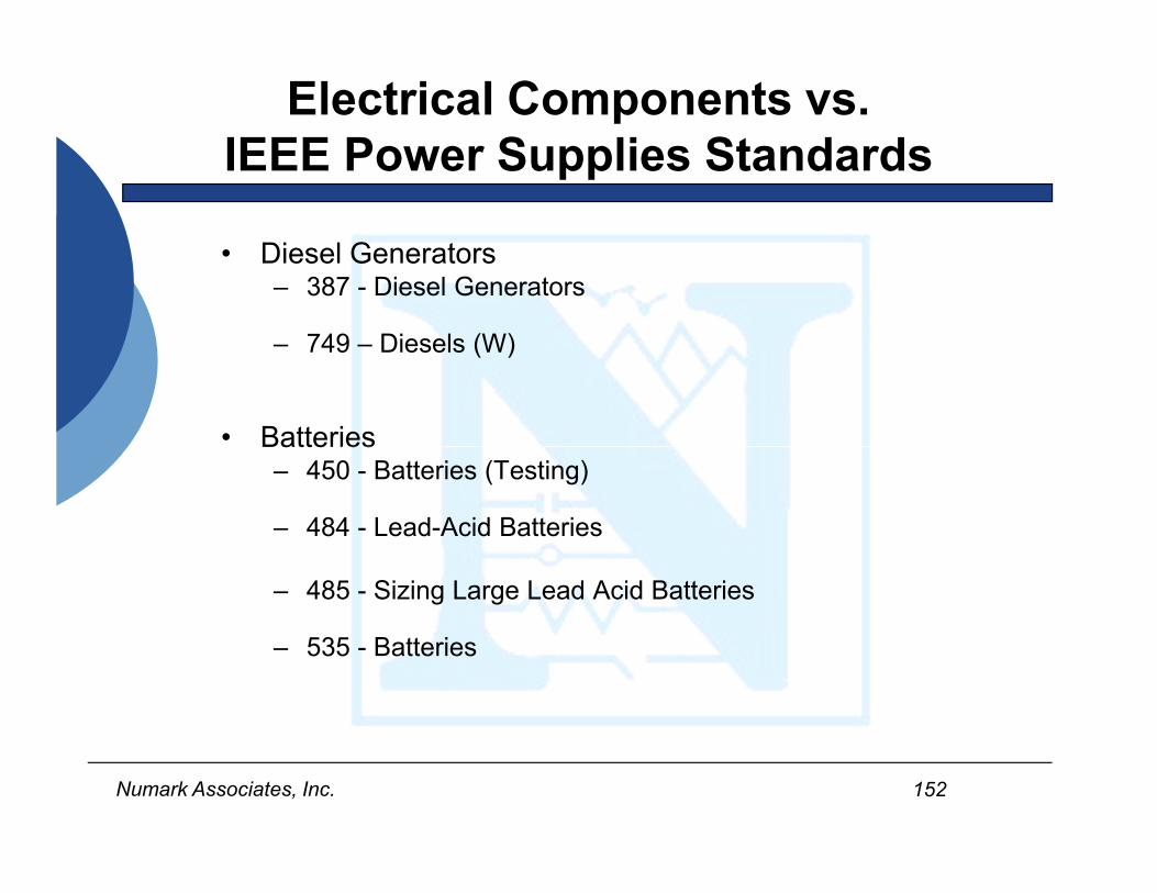
Electrical Components vs. IEEE Power Supplies Standards
• Diesel Generators– 387 - Diesel Generators
– 749 – Diesels (W)
• Batteries
152Numark Associates, Inc.
atte es– 450 - Batteries (Testing)
– 484 - Lead-Acid Batteries
– 485 - Sizing Large Lead Acid Batteries
– 535 - Batteries
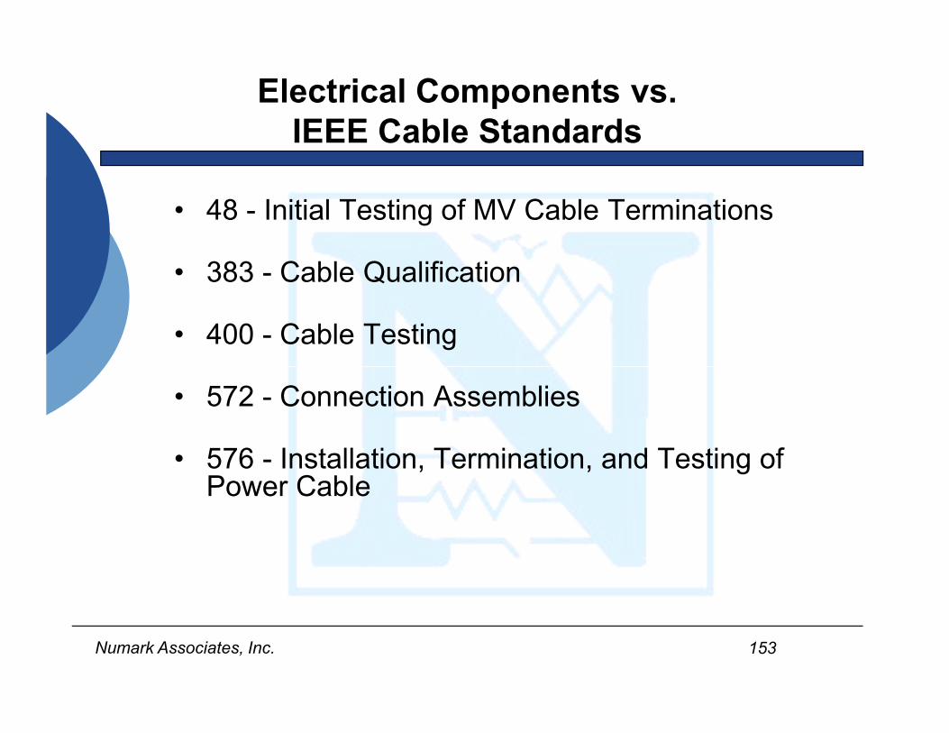
Electrical Components vs. IEEE Cable Standards
• 48 - Initial Testing of MV Cable Terminations
• 383 - Cable Qualification
• 400 - Cable Testing
153Numark Associates, Inc.
• 572 - Connection Assemblies
• 576 - Installation, Termination, and Testing of Power Cable
Electrical Components vs. IEEE Cable Standards
• 628 - Raceways
• 634 - Cable Penetration Fire Stops
• 690 - Cable Systems
154Numark Associates, Inc.
• 690 - Cable Systems
• 835 - Power Cable Ampacity Tables
• 848 - Ampacity Derating of Fire-Protected Cables
Electrical Components vs. IEEE Cable Standards
• 1120 - Submarine Cable Installation
• 1143 - Low Voltage Cable Shielding
• 1185 - Cable Installation Methods
155Numark Associates, Inc.
• 1185 - Cable Installation Methods
• 1202 - Flame Tests for Cables
• 1210 - Cable Lubricant Compatibility
Electrical Components vs. IEEE Power Electronics Stds
• 650 - Battery Chargers and Inverters
944 T i UPS
156Numark Associates, Inc.
• 944 - Testing UPS

Electrical Components vs. IEEE Motor Standards
• 334 - Continuous Duty Motors
• 382 - Value Actuators
1290 MOV A li ti C t l P t ti
157Numark Associates, Inc.
• 1290 - MOV Application, Control, Protection and Testing
• 1349 - Hazardous Duty Motors

Electrical Components vs. IEEE Protective Device Stds
• 649 - Motor Control Centers
• 741 - Protection of Class 1E Power Systems
• 946 - DC Auxiliary Power
158Numark Associates, Inc.
• 1375 - Protection of DC Systems
• 1458 - Molded Case Circuit Breakers
• 1590 - Molded Case Circuit Breakers
• C62.23 - Surge Protection