electrical controls - auburn university
TRANSCRIPT


• Contact blocks include normally open (NO), normally closed (NC), or both NO and NC contacts.
2

• A joystick is used to control many different circuit operations from one location.
3

• Limit switches are used to convert a mechanical motion into an electrical signal.
4

• An actuator is the part of a limit switch that transfers the mechanical force of the moving part to the electrical contacts.
5

• A foot switch is used to allow hands-free control or an additional control point.
6

• Direct scan is a method of scanning in which the target is detected as it passes between the transmitter and receiver.
7
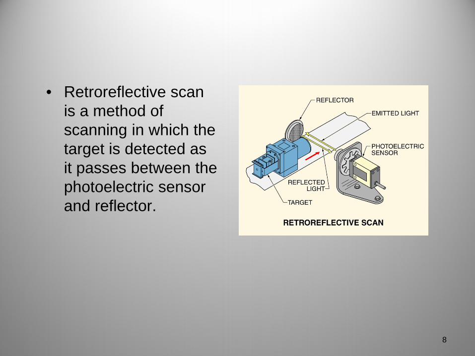
• Retroreflective scan is a method of scanning in which the target is detected as it passes between the photoelectric sensor and reflector.
8

• Diffuse scan is a method of scanning in which the target is detected when some of the emitted, reflected light is received.
9

• Ultrasonic sensors detect objects by bouncing high-frequency sound waves off the object.
10
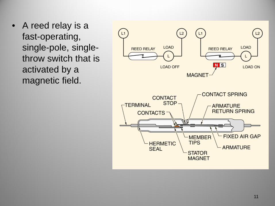
• A reed relay is a fast-operating, single-pole, single-throw switch that is activated by a magnetic field.
11

• Inductive proximity sensors use a magnetic field to detect the presence of a target.
12

• Capacitive proximity sensors use a capacitive field to detect the presence of a target.
13

• Capacitive sensors work based on the dielectric of the material to be sensed.
14
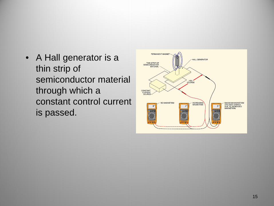
• A Hall generator is a thin strip of semiconductor material through which a constant control current is passed.
15

• Hall effect sensors are available in a variety of packages for different applications.
16

• A line (ladder) diagram consists of a series of symbols interconnected by lines that are laid out like rungs on a ladder to indicate the flow of current through the various components of a circuit.
17

• A solenoid is an electric output device that converts electrical energy into a linear mechanical force.
18

• A contactor is a control device that uses a small control current to energize or de-energize the load connected to it.
19

• The electrical operation of a contactor can be shown using a line diagram, a pictorial drawing, and/or a wiring diagram.
20

• Auxiliary contacts may be added to a contactor to form an electrical holding circuit.
21
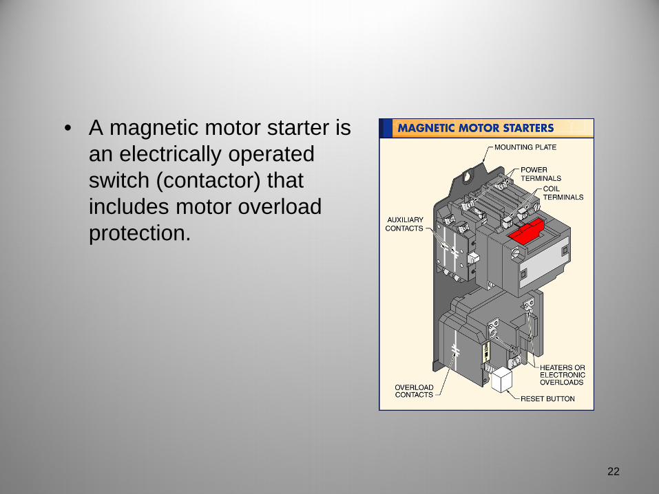
• A magnetic motor starter is an electrically operated switch (contactor) that includes motor overload protection.
22

• The electrical operation of a motor starter can be shown using a line diagram, a pictorial drawing, and/or a wiring diagram.
23
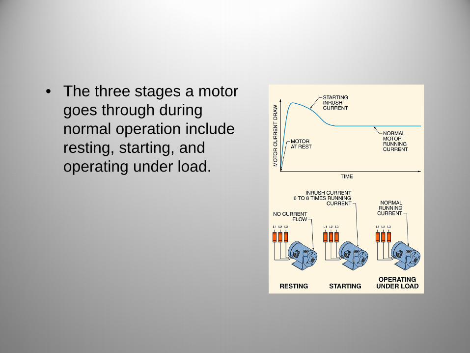
• The three stages a motor goes through during normal operation include resting, starting, and operating under load.

• An overload relay does not open a circuit while a motor is starting, but opens the circuit if the motor gets overloaded and the fuses do not blow.

• In three-wire control, three wires lead from the control device to the starter or contactor.

• A step-down control transformer is used to step down the voltage to the level required in the control circuit.

• Contactors have either an AC coil or a DC coil, but may have either AC or DC contacts.

• A magnetic motor starter is a contactor with overload protection added.
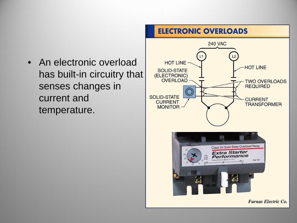
• An electronic overload has built-in circuitry that senses changes in current and temperature.

• Auxiliary contacts are added to give circuits with pushbuttons memory.
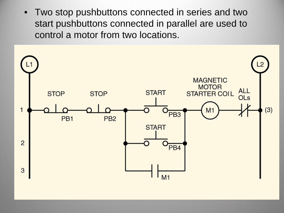
• Two stop pushbuttons connected in series and two start pushbuttons connected in parallel are used to control a motor from two locations.

• Two start/stop stations are used to control two separate magnetic motor starter coils with a common emergency stop protecting the entire system.

• Two motors can be started almost simultaneously from one location to prevent product separation or stretching.
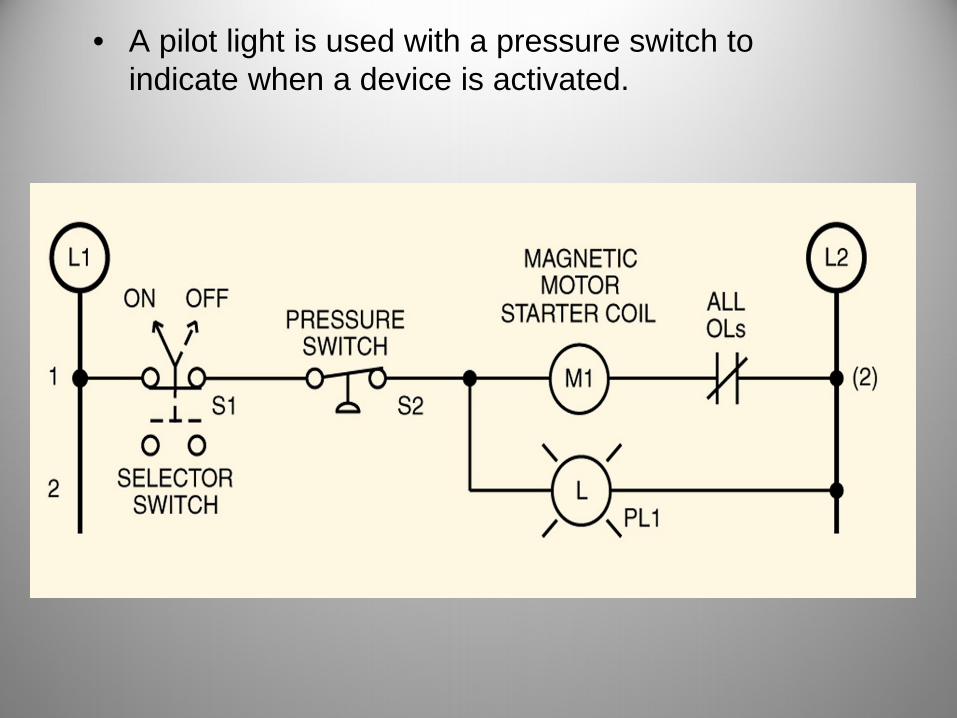
• A pilot light is used with a pressure switch to indicate when a device is activated.

• A pilot light is used with a start/stop station to indicate when a device is activated.

• NOT logic is used to indicate when a device is not operating.

• A sequence control circuit does not let the first conveyor operate unless the second conveyor has started and is running.

• A selector switch is used to provide a common industrial jog/run circuit.
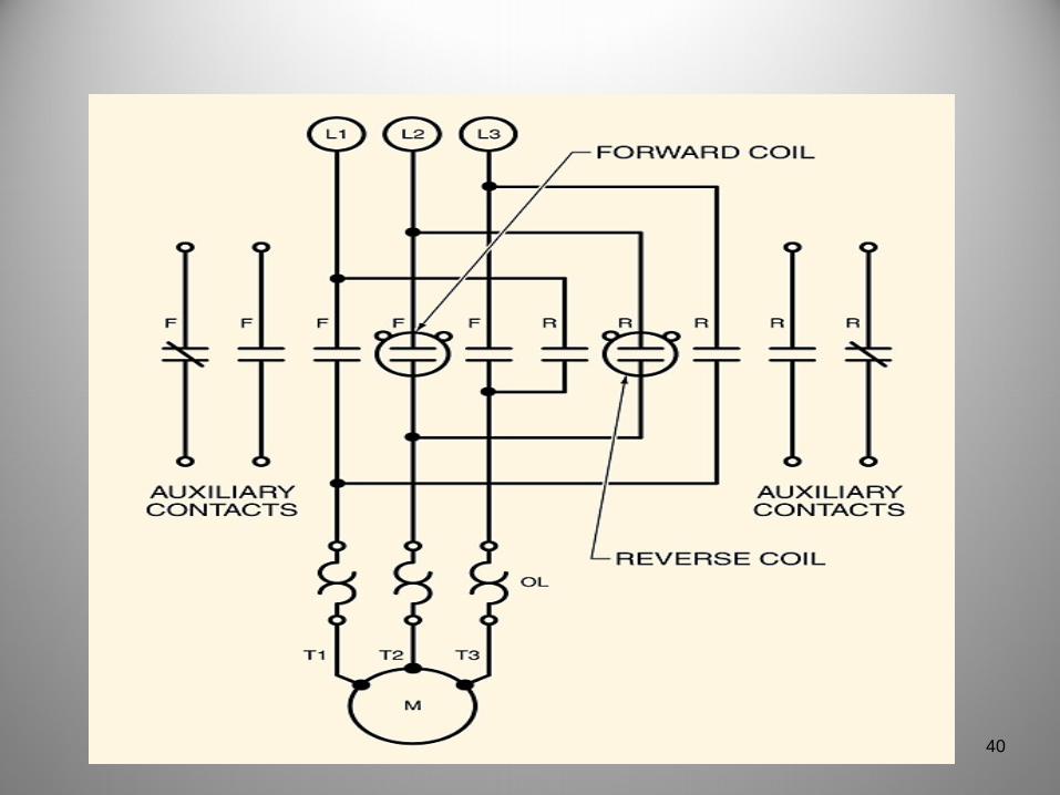
40

• A magnetic reversing starter may be controlled by forward and reverse pushbuttons.
41

42

43

44

45

• A PLC simplifies the wiring of inputs and outputs by eliminating the need for auxiliary contacts on the starter.
46

• Programmable logic relays are versatile and are normally used for control circuits that require numerous relays and/or frequent changes.
47

48

49