electrical machines and energy conversion et3280 march 16, 2015
TRANSCRIPT

Electrical Machines and
Energy Conversion ET3280
March 16, 2015
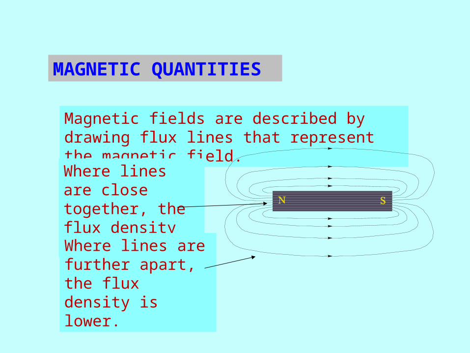
Magnetic fields are described by drawing flux lines that represent the magnetic field.
Where lines are close together, the flux density is higher.
Where lines are further apart, the flux density is lower.
MAGNETIC QUANTITIES

The unit of flux is the weber. The unit of flux density is the weber/square meter, which defines the unit tesla, (T), a very large unit. Flux density is given by the equationwhere
B = flux density (T)j = flux (Wb)A = area (m2)
B=A
F lu x l in e s (
A rea (m )2
MAGNETIC QUANTITIES
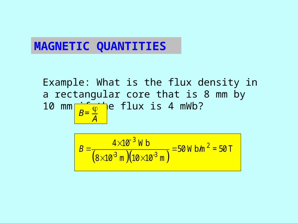
Example: What is the flux density in a rectangular core that is 8 mm by 10 mm if the flux is 4 mWb?
B=A
3
2-3 -3
4 10 Wb50 Wb/m = 50 T
8 10 m 10 10 mB
MAGNETIC QUANTITIES
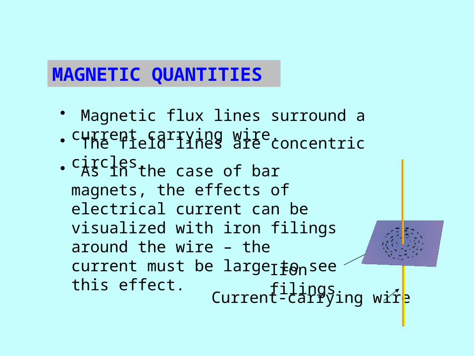
• Magnetic flux lines surround a current carrying wire.
• The field lines are concentric circles.
• As in the case of bar magnets, the effects of electrical current can be visualized with iron filings around the wire – the current must be large to see this effect.
Current-carrying wire
Iron filings
MAGNETIC QUANTITIES

• Permeability (m) defines the ease with which a magnetic field can be established in a given material. It is measured in units of the weber per ampere-turn meter.
• Relative Permeability (mr) is the ratio of the absolute permeability to the permeability of a vacuum.
• The permeability of a vacuum (m0) is 4p x 10-7 weber per ampere-turn meter, which is used as a reference.
0 r
MAGNETIC QUANTITIES
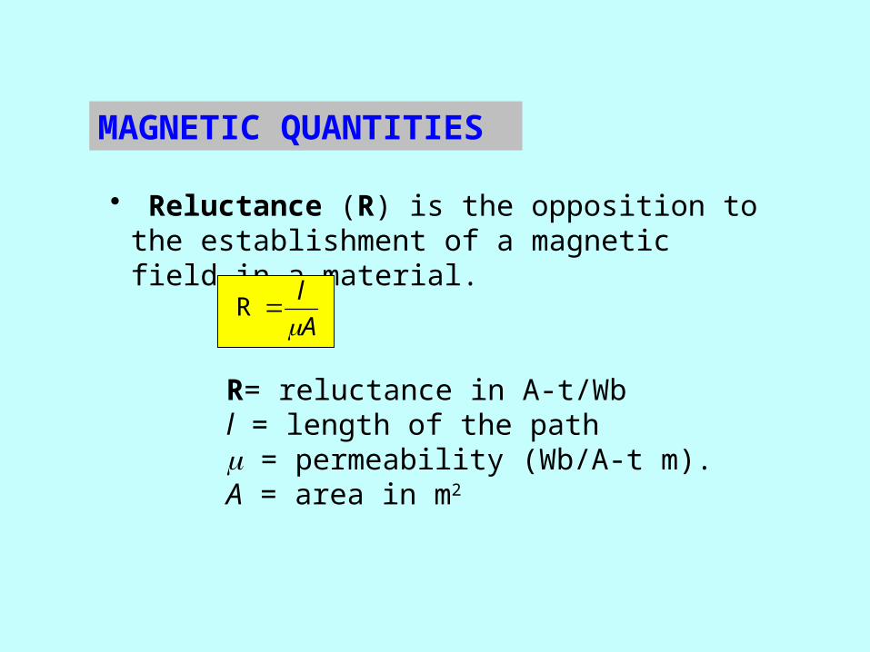
• Reluctance (R) is the opposition to the establishment of a magnetic field in a material.
R= reluctance in A-t/Wbl = length of the pathm = permeability (Wb/A-t m).A = area in m2
A
l
R
MAGNETIC QUANTITIES
Fm = NI
• Recall that magnetic flux lines surround a current-carrying wire. A coil reinforces and intensifies these flux lines. • The cause of magnetic flux is called magnetomotive force (mmf), which is related to the current and number of turns of the coil.
Fm = magnetomotive force (A-t)
N = number of turns of wire in a coil I = current (A)
MAGNETIC QUANTITIES
• Ohm’s law for magnetic circuits is
• flux (j) is analogous to current• magnetomotive force (Fm) is analogous to voltage• reluctance (R) is analogous to resistance.
What flux is in a core that is wrapped with a 300 turn coil with a current of 100 mA if the reluctance of the core is 1.5 x 10⁷ A-t/Wb? 2.0 mWb
RmF
MAGNETIC QUANTITIES

• The magnetomotive force (mmf) is not a true force in the physics sense, but can be thought of as a cause of flux in a core or other material.
Current in the coil causes flux in the iron core.
What is the mmf if a 250 turn coil has 3 A of current?
750 A-t
Iron core
MAGNETIC QUANTITIES

Magnetic field intensity is the magnetomotive force per unit length of a magnetic path.
H= Magnetic field intensity (Wb/A-t m)Fm = magnetomotive force (A-t)
l = average length of the path (m)N = number of turns I = current (A)
H =
F m
l H = NI
lor
Magnetic field intensity represents the effort that a given current must put into establishing a certain flux density in a material.
MAGNETIC QUANTITIES
This relation between B and H is valid up to saturation, when further increase in H has no affect on B.
If a material is permeable, then a greater flux density will occur for a given magnetic field intensity. The relation between B (flux density) and H (the effort to establish the field) is
B = mH
m = permeability (Wb/A-t m).H= Magnetic field intensity (Wb/A-t m)
MAGNETIC QUANTITIES

As the graph shows, the flux density depends on both the material and the magnetic field intensity.
M a g n e tic F ie ld In te n s ity, , (A t/m )H
Flux
den
sity
, ,
(Wb/
/m)
B2
S a tu ra tio n b e g in s
M a g n e tic m a te r ia l
N o n -m a g n e t ic m a te ria l
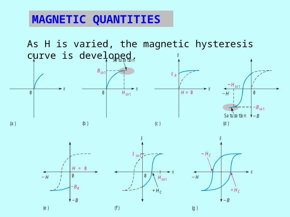
As H is varied, the magnetic hysteresis curve is developed.
(d )(c )
B
H
(b )
B
H
(a )
B
H
(f )
B
H
(g )
B
H
(e )
0 H sa t
Sa tura tio n
0
B sa t B R
H = 0 H
H sa t
B sa t
Sa tura tio n B
H C
0
H0 0H = 0
B R
B
H sa t
B sa t
H C
H
B
H C
MAGNETIC QUANTITIES
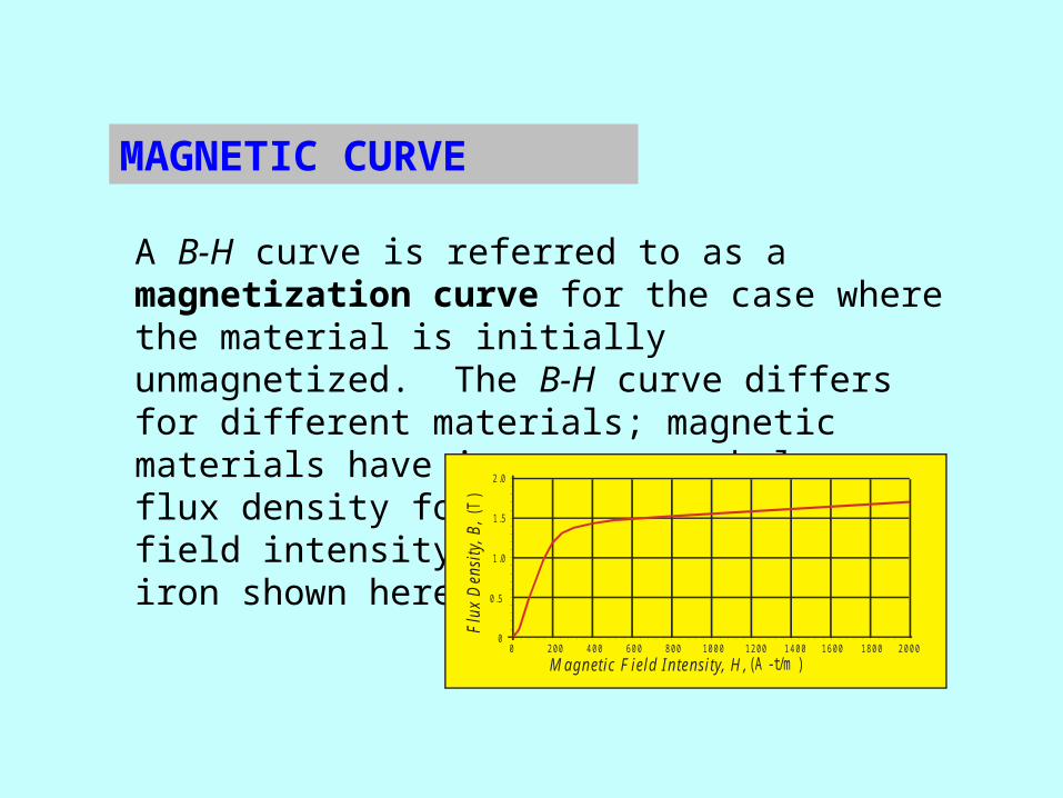
A B-H curve is referred to as a magnetization curve for the case where the material is initially unmagnetized. The B-H curve differs for different materials; magnetic materials have in common much larger flux density for a given magnetic field intensity, such as the annealed iron shown here.
M agn etic F ie ld In tensity, H , (A -t/m )200 400 600 800 1000 1200 16001400 1800 2000
0
0 .5
1 .0
1 .5
2 .0
0
Flu
x D
ensi
ty, B
, (T
)
Annealed iron
MAGNETIC CURVE

When a wire is moved across a magnetic field, there is a relative motion between the wire and the magnetic field.
When a magnetic field is moved past a stationary wire, there is also relative motion.
NS
NS
In either case, the relative motion results in an induced voltage in the wire.
MAGNETIC MOTION

The induced voltage due to the relative motion between the conductor and the magnetic field when the motion is perpendicular to the field is dependent on three factors:
• the flux density
• the length of the conductor in the magnetic field
• the relative velocity (motion is perpendicular)
INDUCED VOLTAGE

Faraday experimented with generating current by relative motion between a magnet and a coil of wire. The amount of voltage induced across a coil is determined by two factors:
1. The rate of change of the magnetic flux with respect to the coil.
NS
V- +Voltage is indicated only when magnet is moving.
FARADAY’S LAW

Faraday also experimented generating current by relative motion between a magnet and a coil of wire. The amount of voltage induced across a coil is determined by two factors:
1. The rate of change of the magnetic flux with respect to the coil.
2. The number of turns of wire in the coil.
NS
V- +Voltage is indicated only when magnet is moving.
FARADAY’S LAW
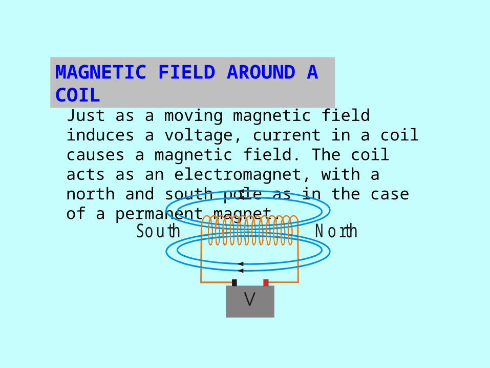
Just as a moving magnetic field induces a voltage, current in a coil causes a magnetic field. The coil acts as an electromagnet, with a north and south pole as in the case of a permanent magnet.
No rthSo uth
MAGNETIC FIELD AROUND A COIL
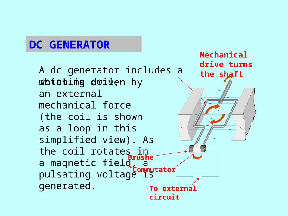
A dc generator includes a rotating coil,
DC GENERATORMechanical drive turns the shaft
which is driven by an external mechanical force (the coil is shown as a loop in this simplified view). As the coil rotates in a magnetic field, a pulsating voltage is generated.
Brushes
Commutator
To external circuit

Magnetic flux densityFlux
Magnetizing force
Magnetomotive force
Permeability
Tesla
Weber
Weber/ampere-turn-meter
Ampere-turn/Weber
Ampere-turn
Ampere-turn/meter
B
fmRFm
H
Reluctance
It is useful to review the key magnetic units from this chapter:
Quantity SI Unit Symbol
MAGNETIC UNITS
Magnetic field
Magnetic flux
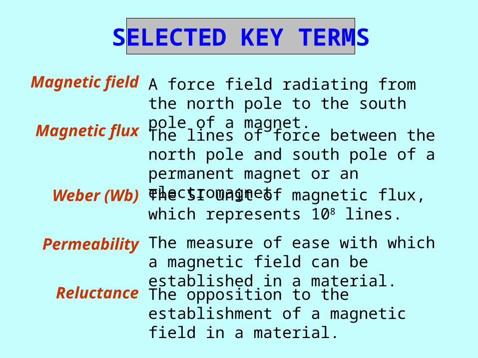
Weber (Wb)
Permeability
Reluctance
The lines of force between the north pole and south pole of a permanent magnet or an electromagnet.The SI unit of magnetic flux, which represents 108 lines.
A force field radiating from the north pole to the south pole of a magnet.
SELECTED KEY TERMS
The measure of ease with which a magnetic field can be established in a material.
The opposition to the establishment of a magnetic field in a material.
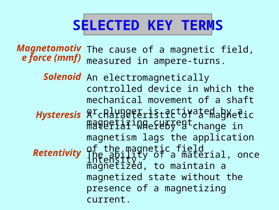
Magnetomotive force (mmf)
Solenoid
Hysteresis
Retentivity
An electromagnetically controlled device in which the mechanical movement of a shaft or plunger is activated by a magnetizing current.
A characteristic of a magnetic material whereby a change in magnetism lags the application of the magnetic field intensity.
The cause of a magnetic field, measured in ampere-turns.
SELECTED KEY TERMS
The ability of a material, once magnetized, to maintain a magnetized state without the presence of a magnetizing current.

Induced voltage (vind)
Faraday’s law
Lenz’s law
A law stating that the voltage induced across a coil of wire equals the number of turns in the coil times the rate of change of the magnetic flux.
Voltage produced as a result of a changing magnetic field.
SELECTED KEY TERMS
A law stating that when the current through a coil changes, the polarity of the induced voltage created by the changing magnetic field is such that it always opposes the change in the current that caused it. The current cannot change instantaneously.

QUIZ
1. A unit of flux density that is the same as a Wb/m2 is the
a. ampere-turn
b. ampere-turn/weber
c. ampere-turn/meter
d. tesla

Quiz
2. If one magnetic circuit has a larger flux than a second magnetic circuit, then the first circuit has
a. a higher flux density
b. the same flux density
c. a lower flux density
d. answer depends on the particular circuit.
Quiz
3. The cause of magnetic flux is
a. magnetomotive force
b. induced voltage
c. induced current
d. hysteresis

Quiz
4. The measurement unit for permeability is
a. weber/ampere-turn
b. ampere-turn/weber
c. weber/ampere-turn-meter
d. dimensionless

Quiz
5. The measurement unit for relative permeability is
a. weber/ampere-turn
b. ampere-turn/weber
c. weber/ampere-turn meter
d. dimensionless

Quiz
6. The property of a magnetic material to behave as if it had a memory is called
a. remembrance
b. hysteresis
c. reluctance
d. permittivity

Quiz
7. Ohm’s law for a magnetic circuit is
a.
b.
c.
d.
Fm = NI
B = mH
A
l
R
RmF

Quiz
8. The control voltage for a relay is applied to the
a. normally-open contacts
b. normally-closed contacts
c. coil
d. armature
Quiz
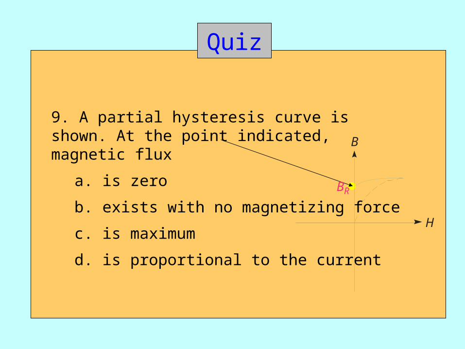
9. A partial hysteresis curve is shown. At the point indicated, magnetic flux
a. is zero
b. exists with no magnetizing force
c. is maximum
d. is proportional to the current
B
H
BR
Quiz
10. When the current through a coil changes, the induced voltage across the coil will
a. oppose the change in the current that caused it
b. add to the change in the current that caused it
c. be zero
d. be equal to the source voltage

Quiz
Answers:
1. d
2. d
3. a
4. c
5. d
6. b
7. c
8. c
9. b
10. a

Electrical Machines and
Energy Conversion
UNIT 1DC GENERATOR BASICS
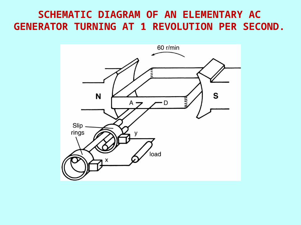
SCHEMATIC DIAGRAM OF AN ELEMENTARY AC GENERATOR TURNING AT 1 REVOLUTION PER SECOND.

VOLTAGE INDUCED IN THE AC GENERATOR AS A FUNCTION OF THE ANGLE OF ROTATION.

VOLTAGE INDUCED AS A FUNCTION OF TIME.
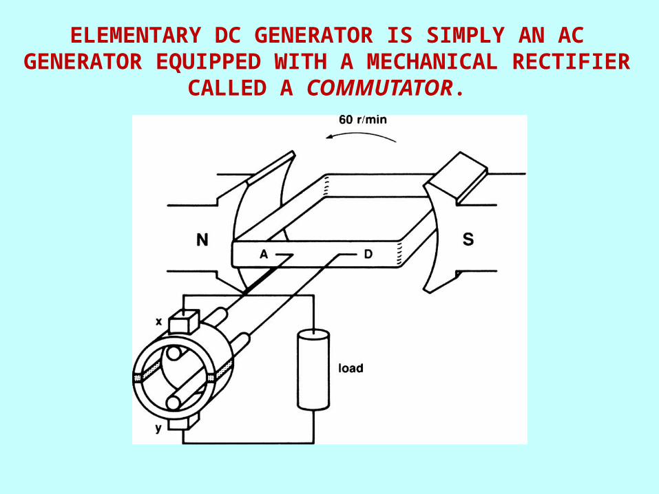
ELEMENTARY DC GENERATOR IS SIMPLY AN AC GENERATOR EQUIPPED WITH A MECHANICAL RECTIFIER
CALLED A COMMUTATOR.
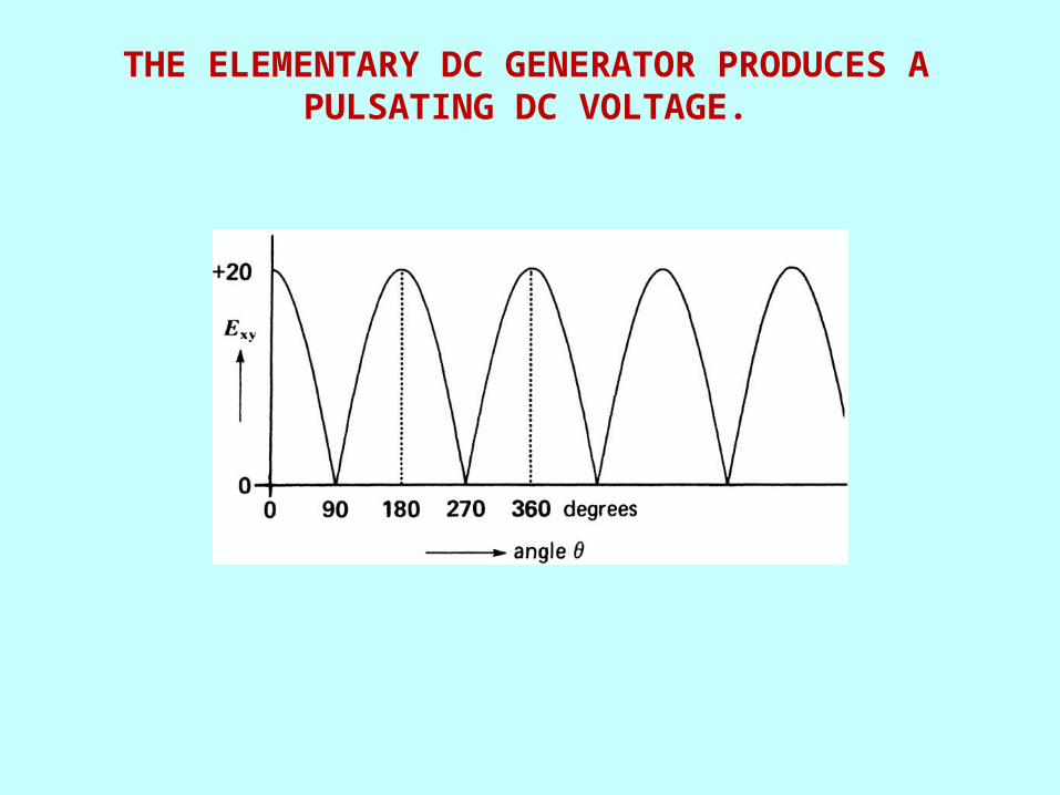
THE ELEMENTARY DC GENERATOR PRODUCES A PULSATING DC VOLTAGE.

THE THREE ARMATURES (A), (B), AND (C) HAVE IDENTICAL WINDINGS. DEPENDING UPON HOW THEY
ARE CONNECTED (TO SLIP RINGS OR A COMMUTATOR), AN AC OR DC VOLTAGE IS OBTAINED.

SCHEMATIC DIAGRAM OF A DC GENERATOR HAVING 4 COILS AND 4 COMMUTATOR BARS

THE VOLTAGE BETWEEN THE BRUSHES IS MORE UNIFORM THAN IN FIG. 4.5.
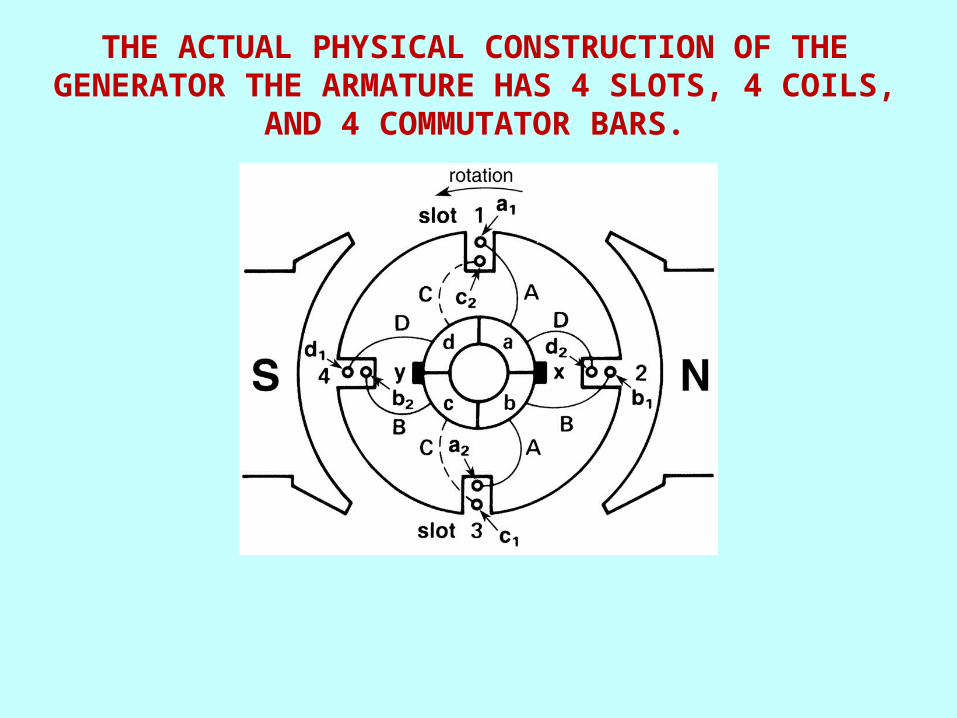
THE ACTUAL PHYSICAL CONSTRUCTION OF THE GENERATOR THE ARMATURE HAS 4 SLOTS, 4 COILS,
AND 4 COMMUTATOR BARS.

POSITION OF THE COILS WHEN THE ARMATURE HAS ROTATED THROUGH 45.

MAGNETIC FIELD PRODUCED BY THE CURRENT FLOWING IN THE ARMATURE CONDUCTORS.

ARMATURE REACTION DISTORTS THE FIELD PRODUCED BY THE N, S POLES.

COMMUTATING POLES PRODUCE AN MMFC THAT OPPOSES THE MMFA OF THE ARMATURE.
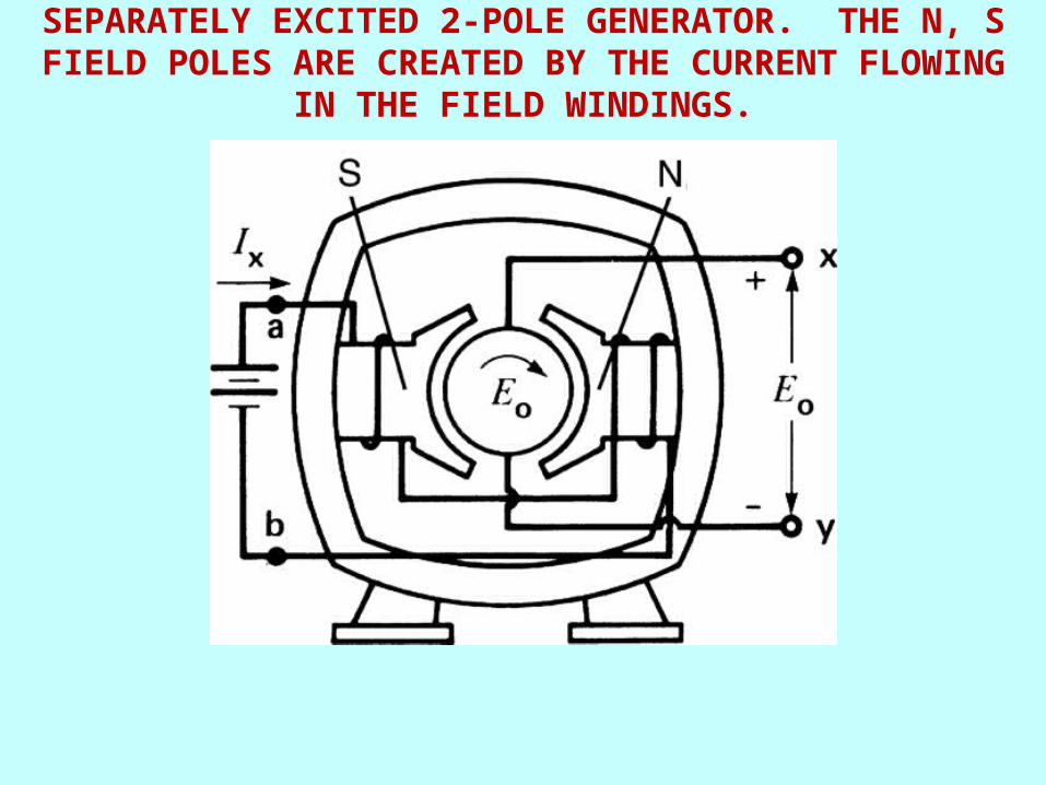
SEPARATELY EXCITED 2-POLE GENERATOR. THE N, S FIELD POLES ARE CREATED BY THE CURRENT FLOWING IN
THE FIELD WINDINGS.

FLUX PER POLE VERSUS EXCITING CURRENT.

SATURATION CURVE OF A DC GENERATOR.
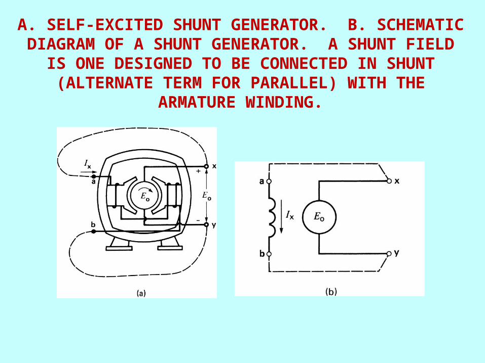
A. SELF-EXCITED SHUNT GENERATOR. B. SCHEMATIC DIAGRAM OF A SHUNT GENERATOR. A SHUNT FIELD IS
ONE DESIGNED TO BE CONNECTED IN SHUNT (ALTERNATE TERM FOR PARALLEL) WITH THE
ARMATURE WINDING.
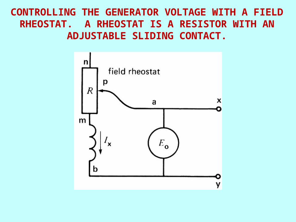
CONTROLLING THE GENERATOR VOLTAGE WITH A FIELD RHEOSTAT. A RHEOSTAT IS A RESISTOR WITH AN
ADJUSTABLE SLIDING CONTACT.
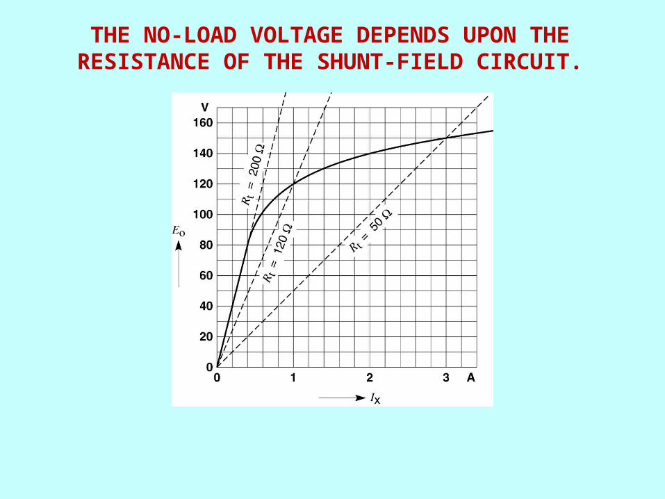
THE NO-LOAD VOLTAGE DEPENDS UPON THE RESISTANCE OF THE SHUNT-FIELD CIRCUIT.

EQUIVALENT CIRCUIT OF A DC GENERATOR

SEPARATELY EXCITED GENERATOR UNDER LOAD
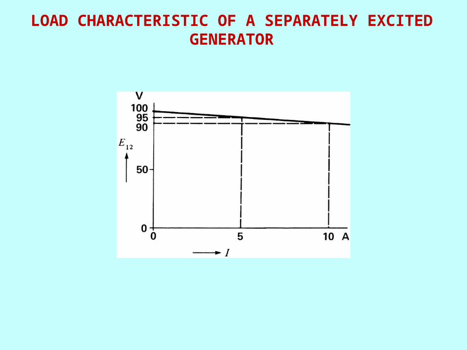
LOAD CHARACTERISTIC OF A SEPARATELY EXCITED GENERATOR
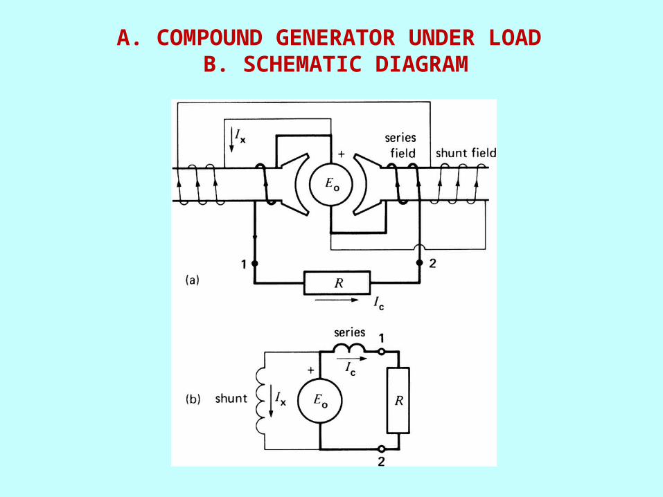
A. COMPOUND GENERATOR UNDER LOAD B. SCHEMATIC DIAGRAM
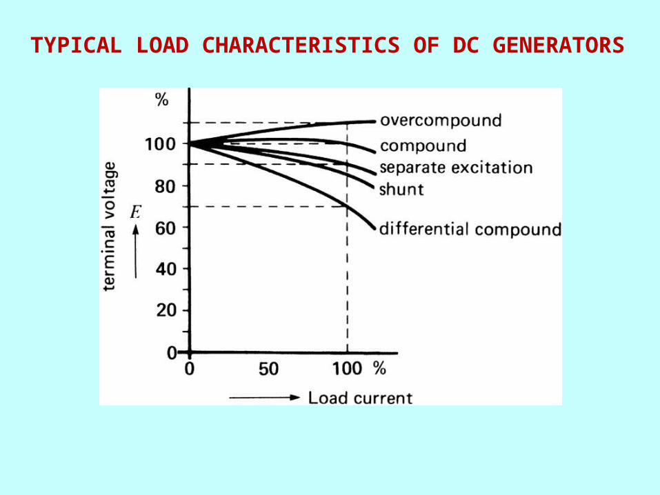
TYPICAL LOAD CHARACTERISTICS OF DC GENERATORS
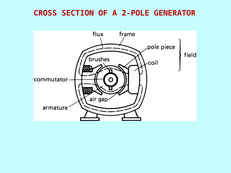
CROSS SECTION OF A 2-POLE GENERATOR

CUTAWAY VIEW OF A 4-POLE SHUNT GENERATOR. IT HAS 3 BRUSHES PER BRUSH SET
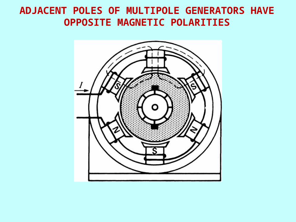
ADJACENT POLES OF MULTIPOLE GENERATORS HAVE OPPOSITE MAGNETIC POLARITIES

ARMATURE OF A DC GENERATOR SHOWING THE COMMUTATOR, STACKED LAMINATIONS, SLOTS, AND SHAFT
(COURTESY OF GENERAL ELECTRIC COMPANY, USA)
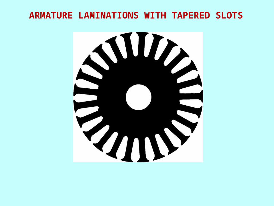
ARMATURE LAMINATIONS WITH TAPERED SLOTS

CROSS-SECTION OF A SLOT CONTAINING 4 CONDUCTORS
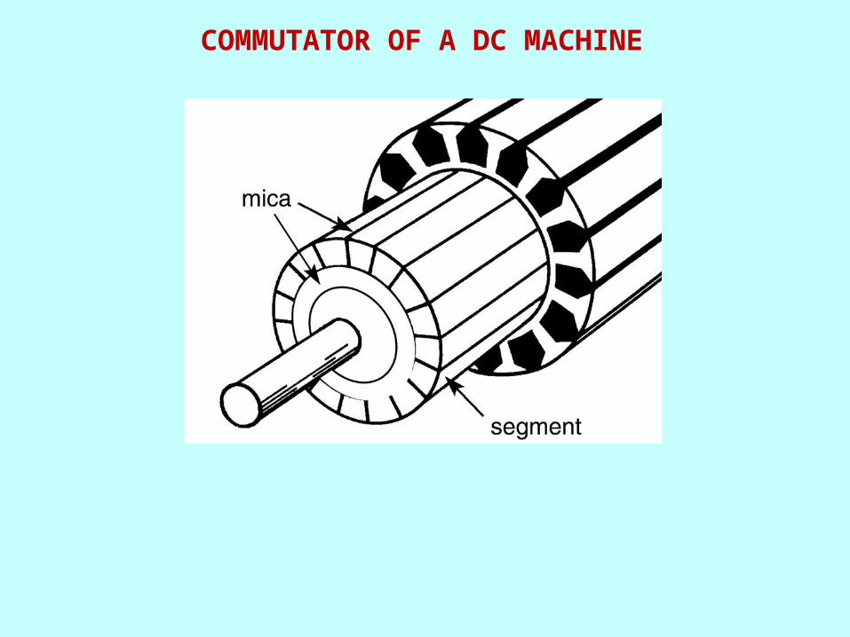
COMMUTATOR OF A DC MACHINE

A. BRUSHES OF A 2-POLE GENERATORB. BRUSHES AND CONNECTIONS OF A 6-POLE GENERATOR

A. CARBON BRUSH AND ULTRA FLEXIBLE COPPER LEAD. B. BRUSH HOLDER AND SPRING TO EXERT PRESSURE
C. BRUSH SET COMPOSED OF TWO BRUSHES, MOUNTED ON ROCKER ARM (COURTESY OF GENERAL ELECTRIC COMPANY, USA)
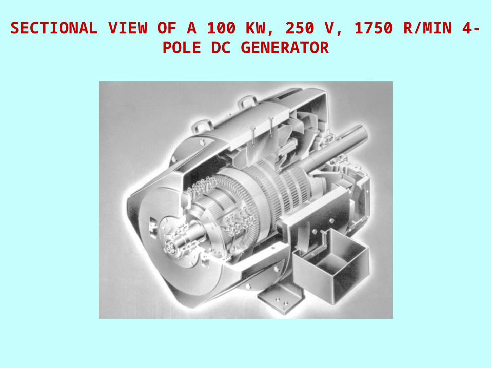
SECTIONAL VIEW OF A 100 KW, 250 V, 1750 R/MIN 4-POLE DC GENERATOR
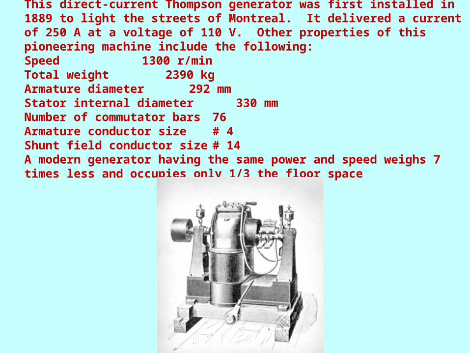
This direct-current Thompson generator was first installed in 1889 to light the streets of Montreal. It delivered a current of 250 A at a voltage of 110 V. Other properties of this pioneering machine include the following:Speed 1300 r/minTotal weight 2390 kgArmature diameter 292 mmStator internal diameter 330 mmNumber of commutator bars 76Armature conductor size # 4Shunt field conductor size # 14A modern generator having the same power and speed weighs 7 times less and occupies only 1/3 the floor space

SCHEMATIC DIAGRAM OF A 12-POLE, 72-COIL DC GENERATOR.


Electrical Machines
and Energy Conversion
Unit 1DC Series Motor Basics
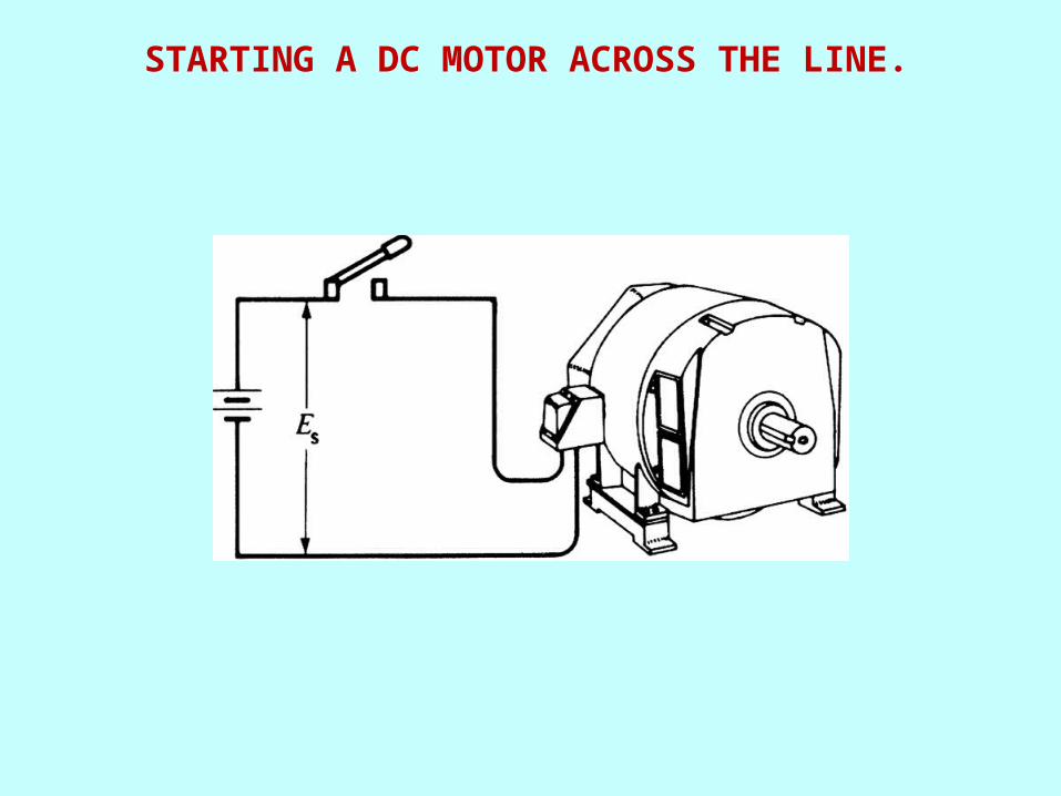
STARTING A DC MOTOR ACROSS THE LINE.

COUNTER-ELECTROMOTIVE FORCE (CEMF) IN A DC MOTOR

START-UP CURRENTS
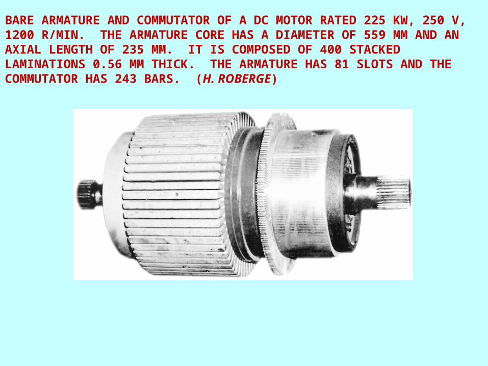
BARE ARMATURE AND COMMUTATOR OF A DC MOTOR RATED 225 KW, 250 V, 1200 R/MIN. THE ARMATURE CORE HAS A DIAMETER OF 559 MM AND AN AXIAL LENGTH OF 235 MM. IT IS COMPOSED OF 400 STACKED LAMINATIONS 0.56 MM THICK. THE ARMATURE HAS 81 SLOTS AND THE COMMUTATOR HAS 243 BARS. (H. ROBERGE)

A. ARMATURE IN THE PROCESS OF BEING WOUND; COIL-FORMING MACHINE GIVES THE COILS THE DESIRED SHAPE. B. ONE OF THE 81 COILS READY TO BE PLACED IN THE SLOTS. C. CONNECTING THE COIL ENDS TO THE COMMUTATOR BARS. D. COMMUTATOR CONNECTIONS READ FOR BRAZING. (H. ROBERGE)
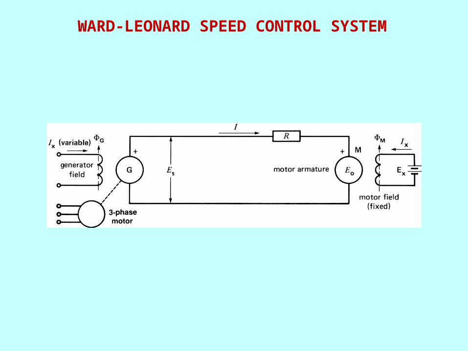
WARD-LEONARD SPEED CONTROL SYSTEM
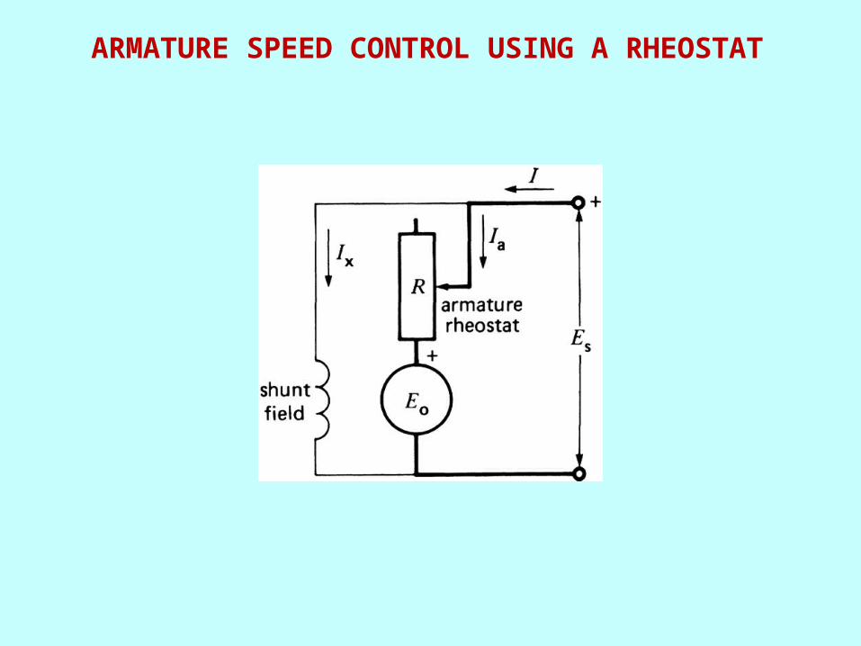
ARMATURE SPEED CONTROL USING A RHEOSTAT

A. SCHEMATIC DIAGRAM OF A SHUNT MOTOR INCLUDING THE FIELD RHEOSTATB. TORQUE-SPEED AND TORQUE-CURRENT CHARACTERISTIC OF A SHUNT MOTOR
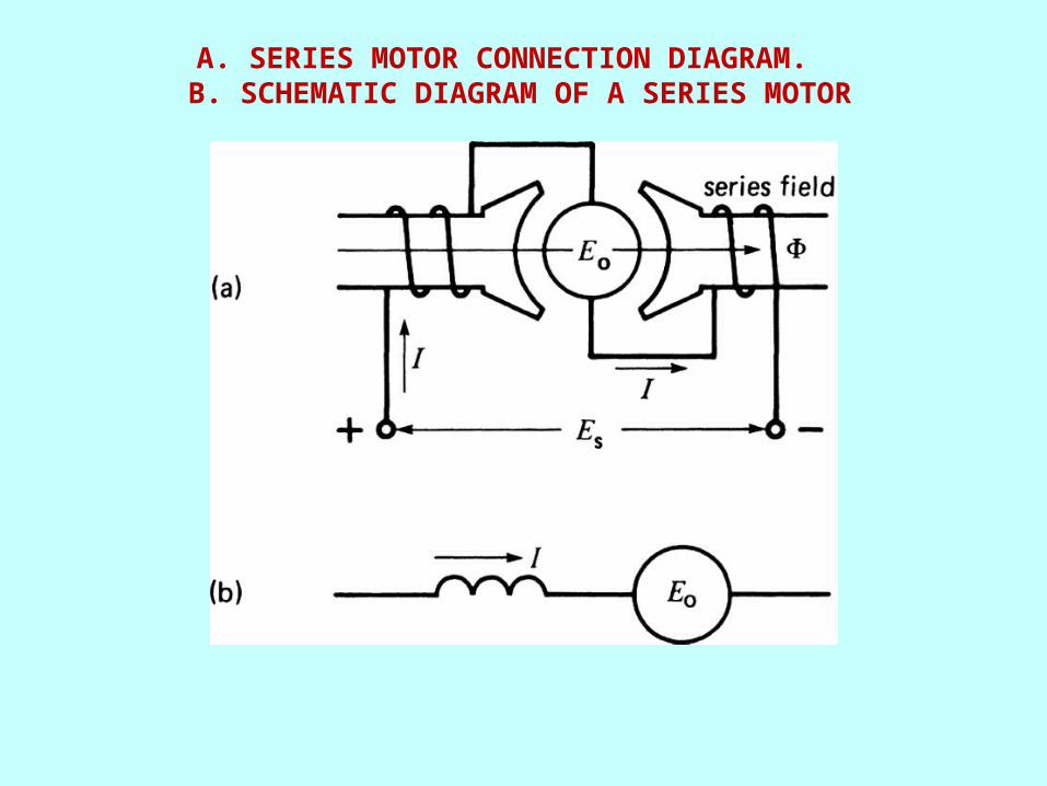
A. SERIES MOTOR CONNECTION DIAGRAM. B. SCHEMATIC DIAGRAM OF A SERIES MOTOR

TYPICAL SPEED-TORQUE AND CURRENT-TORQUE CHARACTERISTIC OF A SERIES MOTOR.
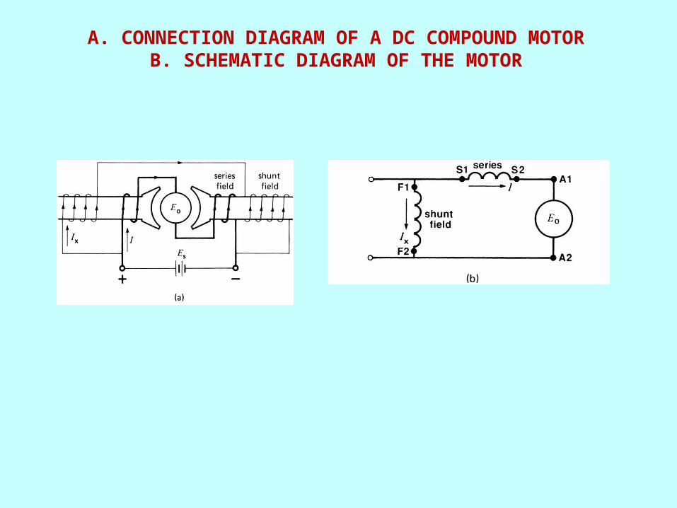
A. CONNECTION DIAGRAM OF A DC COMPOUND MOTORB. SCHEMATIC DIAGRAM OF THE MOTOR
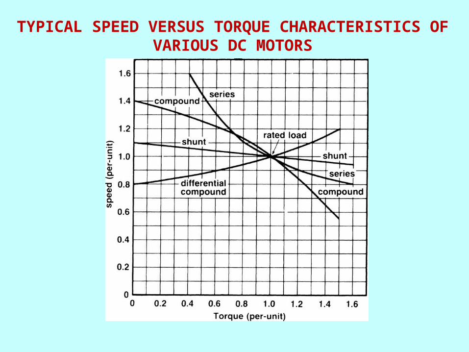
TYPICAL SPEED VERSUS TORQUE CHARACTERISTICS OF VARIOUS DC MOTORS
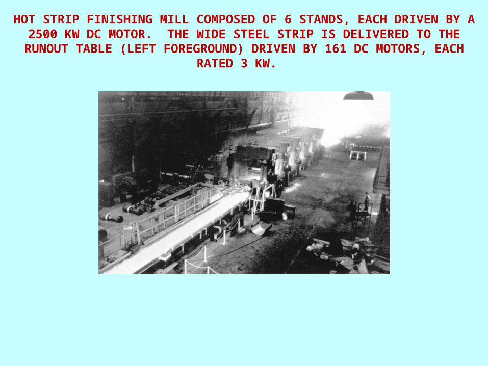
HOT STRIP FINISHING MILL COMPOSED OF 6 STANDS, EACH DRIVEN BY A 2500 KW DC MOTOR. THE WIDE STEEL STRIP IS DELIVERED TO THE RUNOUT TABLE
(LEFT FOREGROUND) DRIVEN BY 161 DC MOTORS, EACH RATED 3 KW.

A. ORIGINAL CONNECTIONS OF A COMPOUND MOTORB. REVERSING THE ARMATURE CONNECTIONS TO REVERSE THE DIRECTION OF ROTATIONC. REVERSING THE FIELD CONNECTIONS TO REVERSE THE DIRECTION OF ROTATION

PERMANENT MAGNET MOTOR RATED 1.5 HP, 90 V, 2900 R/MIN, 14.5 A. ARMATURE DIAMETER: 73 MM; ARMATURE LENGTH: 115 MM; SLOTS 20; COMMUTATOR BARS: 40; TURNS PER COIL: 5; CONDUCTOR SIZE: NO.17 AWG, LAP WINDING ARMATURE RESISTANCE AT 20C: 0.34
Electrical Machines and Energy Conversion
End of Presentation
