electrical machines ii unit i alternator - fmcetfmcet.in/eee/ee2302_uw.pdf · ·...
TRANSCRIPT
y
ELECTRICAL MACHINES – II
UNIT I
ALTERNATOR
Basic Principle
A.C. generators or Alternators (as they are usuallcalled) operate on the same fundamental principles ofelectro magnetic induction as D.C. generators. They alsoconsist of an armature winding and a magnetic field. Butthere is one important difference between the two.
Whereas in D.C. generators, the armature rotatesAnd the field system is stationary, the arrangement in
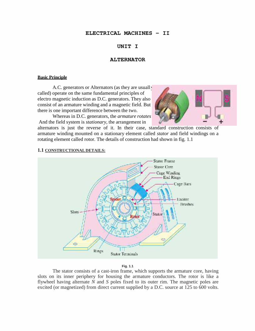
alternators is just the reverse of it. In their case, standard construction consists ofarmature winding mounted on a stationary element called stator and field windings on arotating element called rotor. The details of construction had shown in fig. 1.1
1.1 CONSTRUCTIONAL DETAILS:
Fig. 1.1The stator consists of a cast-iron frame, which supports the armature core, having
slots on its inner periphery for housing the armature conductors. The rotor is like aflywheel having alternate N and S poles fixed to its outer rim. The magnetic poles areexcited (or magnetized) from direct current supplied by a D.C. source at 125 to 600 volts.
In most cases, necessary exciting (or magnetizing) current is obtained from a small D.C.shunt generator which is belted or mounted on the shaft of the alternator itself.
Because the field magnets are rotating, this current is supplied through two sliprings. As the exciting voltage is relatively small, the slip-rings and brush gear are of lightconstruction. Recently, brushless excitation systems have been developed in which a3-phase A.C. exciter and a group of rectifiers supply D.C. to the alternator.Hence, brushes, slip-rings and commutator are eliminated.
When the rotor rotates, the stator conductors (being stationary)are cut by the magnetic flux, hence they have induced E.M.F. producedin them. Because the magnetic poles are alternately N and S, theyinduce an E.M.F. and hence current in armature conductors, whichfirst flows in one direction and then in the other. Hence, an alternatingE.M.F. is produced in the stator conductors (i) whose frequency dependson the number of N and S poles moving past a conductor in one second and (ii) whosedirection is given by Fleming's Right-hand rule.
1. Stator Frame
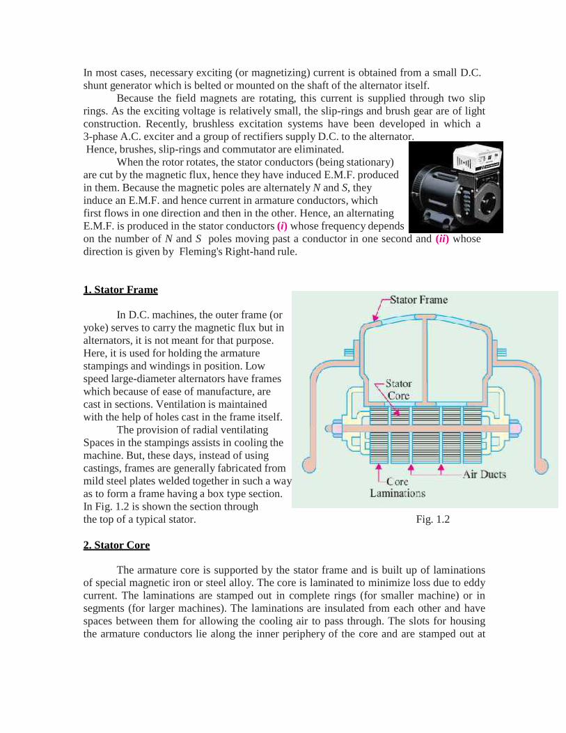
In D.C. machines, the outer frame (oryoke) serves to carry the magnetic flux but inalternators, it is not meant for that purpose.Here, it is used for holding the armaturestampings and windings in position. Lowspeed large-diameter alternators have frameswhich because of ease of manufacture, arecast in sections. Ventilation is maintainedwith the help of holes cast in the frame itself.
The provision of radial ventilatingSpaces in the stampings assists in cooling themachine. But, these days, instead of usingcastings, frames are generally fabricated frommild steel plates welded together in such a wayas to form a frame having a box type section.In Fig. 1.2 is shown the section throughthe top of a typical stator. Fig. 1.2
2. Stator Core
The armature core is supported by the stator frame and is built up of laminationsof special magnetic iron or steel alloy. The core is laminated to minimize loss due to eddycurrent. The laminations are stamped out in complete rings (for smaller machine) or insegments (for larger machines). The laminations are insulated from each other and havespaces between them for allowing the cooling air to pass through. The slots for housingthe armature conductors lie along the inner periphery of the core and are stamped out at
.
i.e.
the same time when laminations are formed. Different shapes of the armature slots areshown in Fig. 1.3.
The wide-open type slot (also used InD.C. machines) has the advantage ofPermitting easy installation of form-woundCoils and their easy removal in case of repairBut it has the disadvantage of distributingthe air-gap flux into bunches or tufts, thatProduce ripples in the wave of the generatedE.M.F. The semi-closed type slots are betterin this respect, but do not allow the use ofForm-wound coils. The wholly-closed typeSlots or tunnels do not disturb the air-gap flux Fig. 1.3.but (i) they tend to increase the inductance of the windings (ii) the armature conductorshave to be threaded through, thereby increasing initial lab our and cost of winding and(iii) they present a complicated problem of end connections. Hence, they are rarely used.
1.2 TYPES OF ROTORS:
Two types of rotors are used in alternators(i) salient-pole type and
(ii) smooth-cylindrical type.(i) Salient (or projecting) Pole Type
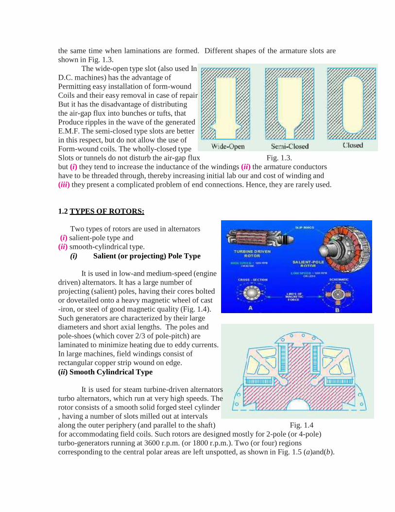
It is used in low-and medium-speed (enginedriven) alternators. It has a large number ofprojecting (salient) poles, having their cores boltedor dovetailed onto a heavy magnetic wheel of cast-iron, or steel of good magnetic quality (Fig. 1.4).Such generators are characterized by their largediameters and short axial lengths. The poles andpole-shoes (which cover 2/3 of pole-pitch) arelaminated to minimize heating due to eddy currents.In large machines, field windings consist ofrectangular copper strip wound on edge.(ii) Smooth Cylindrical Type
It is used for steam turbine-driven alternatorsturbo alternators, which run at very high speeds. Therotor consists of a smooth solid forged steel cylinder, having a number of slots milled out at intervalsalong the outer periphery (and parallel to the shaft) Fig. 1.4for accommodating field coils. Such rotors are designed mostly for 2-pole (or 4-pole)turbo-generators running at 3600 r.p.m. (or 1800 r.p.m.). Two (or four) regionscorresponding to the central polar areas are left unspotted, as shown in Fig. 1.5 (a)and(b).
e
The central polar areas are surrounded bythe field windings placed in slots. The fieldcoils are so arranged around these polarareas that flux density is maximum on thepolar central line and gradually falls awayon either side. It should be noted that inthis case, poles are non-salient i.e. they donot project out from the surface of therotor. To avoid excessive peripheralvelocity, such rotors have very smalldiameters (about 1 metre or so). Hence,turbo-generators are characterised bysmall diameters and very long axial (orrotor) length. The cylindrical constructionof the rotor gives better balance and Fig. 1.5quieter-operation and also less windage losses.
1.2.1 SPEED AND FREQUENCY:
In an alternator, there exists a definite relationshipbetween the rotational speed (N) of the rotor, the frequency(f) of the generated e.m.f. and the number of poles P.
Consider the armature conductor marked X inFig. 1.6 situated at the centre of a N-pole rotating in clockwisdirection. The conductor being situated at the place ofmaximum flux density will have maximum e.m.f. induced init. The direction of the induced e.m.f. is given by Fleming’sright hand rule. But while applying this rule, one should becareful to note that the thumb indicates the direction of themotion of the conductor relative to the field. To an observerstationed on the clockwise revolving poles, the conductorwould seem to be rotating anti-clockwise. Hence, thumb Fig. 1.6should point to the left. The direction of the induced e.m.f. is downwards, in a direction atright angles to the plane of the paper.
When the conductor is in the interpolar gap, as at A in Fig. 1.6, it hasminimum e.m.f. induced in it, because flux density is minimum there. Again, when it is atthe centre of a S-pole, it has maximum e.m.f. induced in it, because flux density at B ismaximum. But the direction of the e.m.f. when conductor is over a N-pole is opposite tothat when it is over a S-pole. Obviously, one cycle of e.m.f. is induced in a conductorwhen one pair of poles passes over it. In other words, the e.m.f. in an armature conductorgoes through one cycle in angular distance equal to twice the pole-pitch, as shown in Fig.1.6.LetP = total number of magnetic poles
N = rotative speed of the rotor in r.p.m.
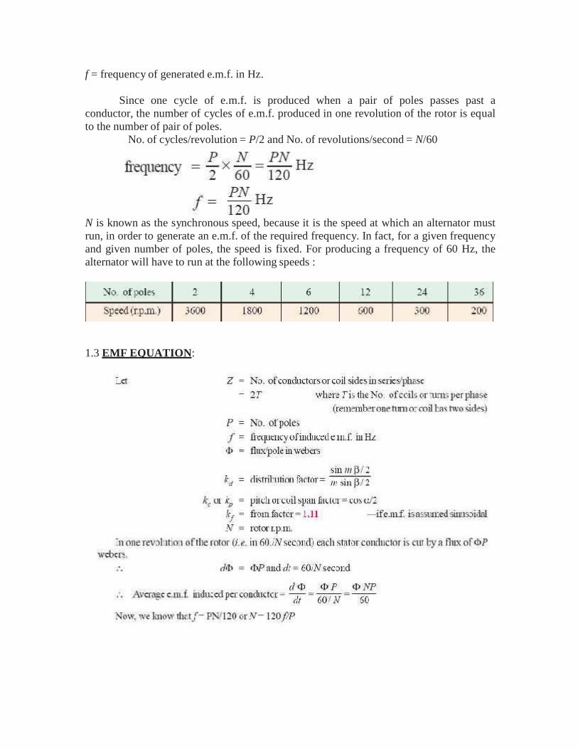
f = frequency of generated e.m.f. in Hz.
Since one cycle of e.m.f. is produced when a pair of poles passes past aconductor, the number of cycles of e.m.f. produced in one revolution of the rotor is equalto the number of pair of poles.
No. of cycles/revolution = P/2 and No. of revolutions/second = N/60
N is known as the synchronous speed, because it is the speed at which an alternator mustrun, in order to generate an e.m.f. of the required frequency. In fact, for a given frequencyand given number of poles, the speed is fixed. For producing a frequency of 60 Hz, thealternator will have to run at the following speeds :
1.3 EMF EQUATION:
1.4 ARMATURE REACTION:
As in d.c. generators, armature reaction is the effect of armature flux on the main fieldflux. In the case of alternators, the power factor of the load has a considerable effecton the armature reaction.
We will consider three cases: (i) when load of p.f. is unity (ii) when p.f. is zerolagging and (iii) when p.f. is zero leading.
Before discussing this, it should be noted that in a 3-phase machine the combinedampere-turn wave (or m.m.f. wave) is sinusoidal which moves synchronously. This amp-turn or m.m.f. wave is fixed relative to the poles, its amplitude is proportional to the loadcurrent, but its position depends on the p.f. of the load.
Consider a 3-phase, 2-pole alternator having a single-layer winding, as shown in Fig.1.7 (a). For the sake of simplicity, assume that winding of each phase is concentrated(instead of being distributed) and that the number of turns per phase is N. Further supposethat the alternator is loaded with a resistive load of unity power factor, so that phasecurrents Ia, Ib and Ic are in phase with their respective phase voltages. Maximum currentIa will flow when the poles are in position shown in Fig. 1.7 (a) or at a time t1 in Fig. 1.7(c). When Ia has a maximum value, Ib and Ic have one-half their maximum values (thearrows attached to Ia , Ib and Ic are only polarity marks and are not meant to give theinstantaneous directions of these currents at time t1). The instantaneous directions ofcurrents are shown in Fig. 1.7 (a). At the instant t1, Ia flows in conductor whereas Iband Ic flow out. As seen from Fig. 1.7 (d), the m.m.f. (= NIm) produced by phase a-a’ishorizontal, whereas that produced by other two phases is (Im/2) N each at 60° to thehorizontal. The total armature m.m.f. is equal to the vector sum of these three m.m.fs.
As seen, at this instant t1, the m.m.f. of the main field is upwards and the armature m.m.f.is behind it by 90 electrical degrees.
Next, let us investigate the armature m.m.f. at instant t2. At this instant, the polesare in the horizontal position. Also Ia = 0, but Ib and Ic are each equal to 0.866 of their
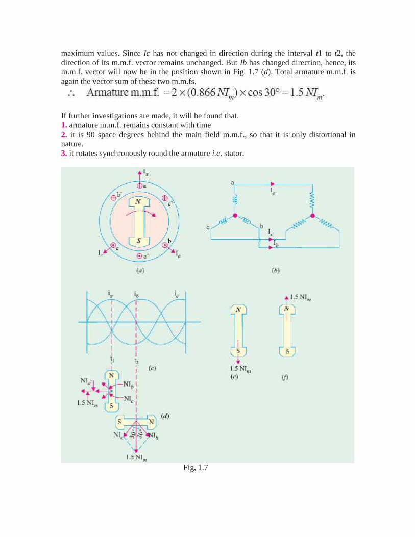
maximum values. Since Ic has not changed in direction during the interval t1 to t2, thedirection of its m.m.f. vector remains unchanged. But Ib has changed direction, hence, itsm.m.f. vector will now be in the position shown in Fig. 1.7 (d). Total armature m.m.f. isagain the vector sum of these two m.m.fs.
If further investigations are made, it will be found that.1. armature m.m.f. remains constant with time2. it is 90 space degrees behind the main field m.m.f., so that it is only distortional innature.3. it rotates synchronously round the armature i.e. stator.
Fig, 1.7
main flux.
°
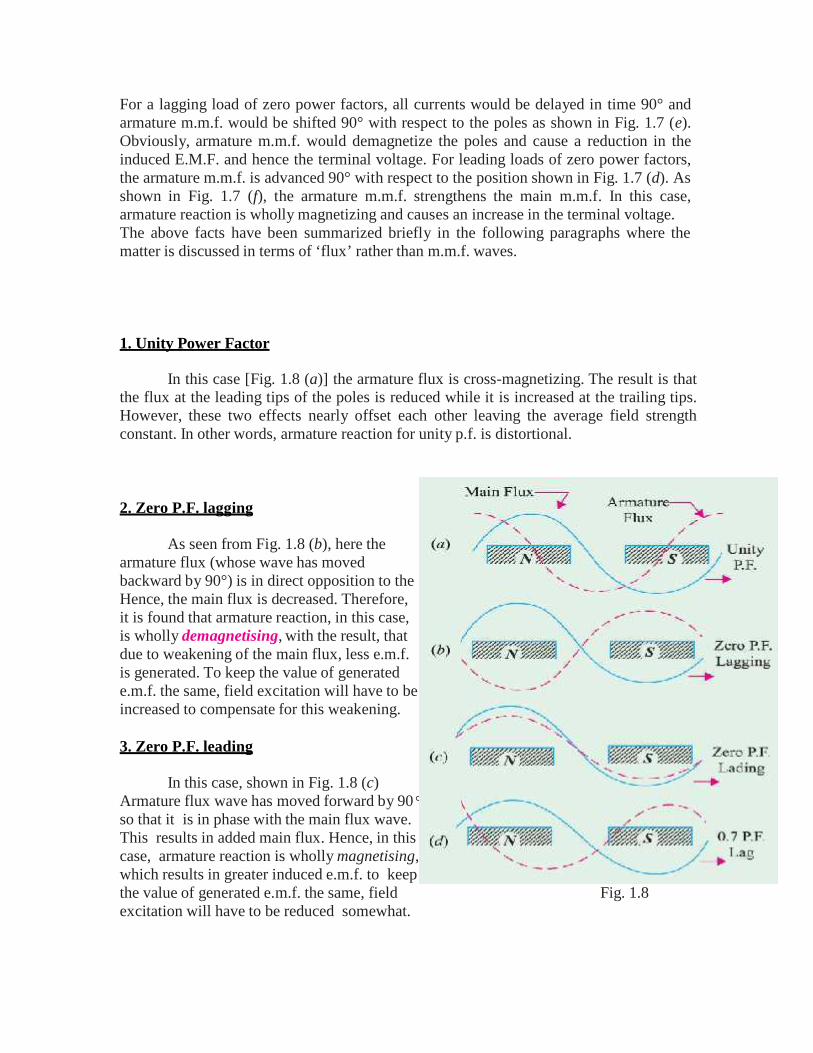
For a lagging load of zero power factors, all currents would be delayed in time 90° andarmature m.m.f. would be shifted 90° with respect to the poles as shown in Fig. 1.7 (e).Obviously, armature m.m.f. would demagnetize the poles and cause a reduction in theinduced E.M.F. and hence the terminal voltage. For leading loads of zero power factors,the armature m.m.f. is advanced 90° with respect to the position shown in Fig. 1.7 (d). Asshown in Fig. 1.7 (f), the armature m.m.f. strengthens the main m.m.f. In this case,armature reaction is wholly magnetizing and causes an increase in the terminal voltage.The above facts have been summarized briefly in the following paragraphs where thematter is discussed in terms of ‘flux’ rather than m.m.f. waves.
1. Unity Power Factor
In this case [Fig. 1.8 (a)] the armature flux is cross-magnetizing. The result is thatthe flux at the leading tips of the poles is reduced while it is increased at the trailing tips.However, these two effects nearly offset each other leaving the average field strengthconstant. In other words, armature reaction for unity p.f. is distortional.
2. Zero P.F. lagging
As seen from Fig. 1.8 (b), here thearmature flux (whose wave has movedbackward by 90°) is in direct opposition to theHence, the main flux is decreased. Therefore,it is found that armature reaction, in this case,is wholly demagnetising, with the result, thatdue to weakening of the main flux, less e.m.f.is generated. To keep the value of generatede.m.f. the same, field excitation will have to beincreased to compensate for this weakening.
3. Zero P.F. leading
In this case, shown in Fig. 1.8 (c)Armature flux wave has moved forward by 90so that it is in phase with the main flux wave.This results in added main flux. Hence, in thiscase, armature reaction is wholly magnetising,which results in greater induced e.m.f. to keepthe value of generated e.m.f. the same, field Fig. 1.8excitation will have to be reduced somewhat.
4. For intermediate power factor [Fig. 1.8 (d)], the effect is partly distortional andpartly demagnetizing (because p.f. is lagging).
1.5 SYNCHRONOUS REACTANCE:
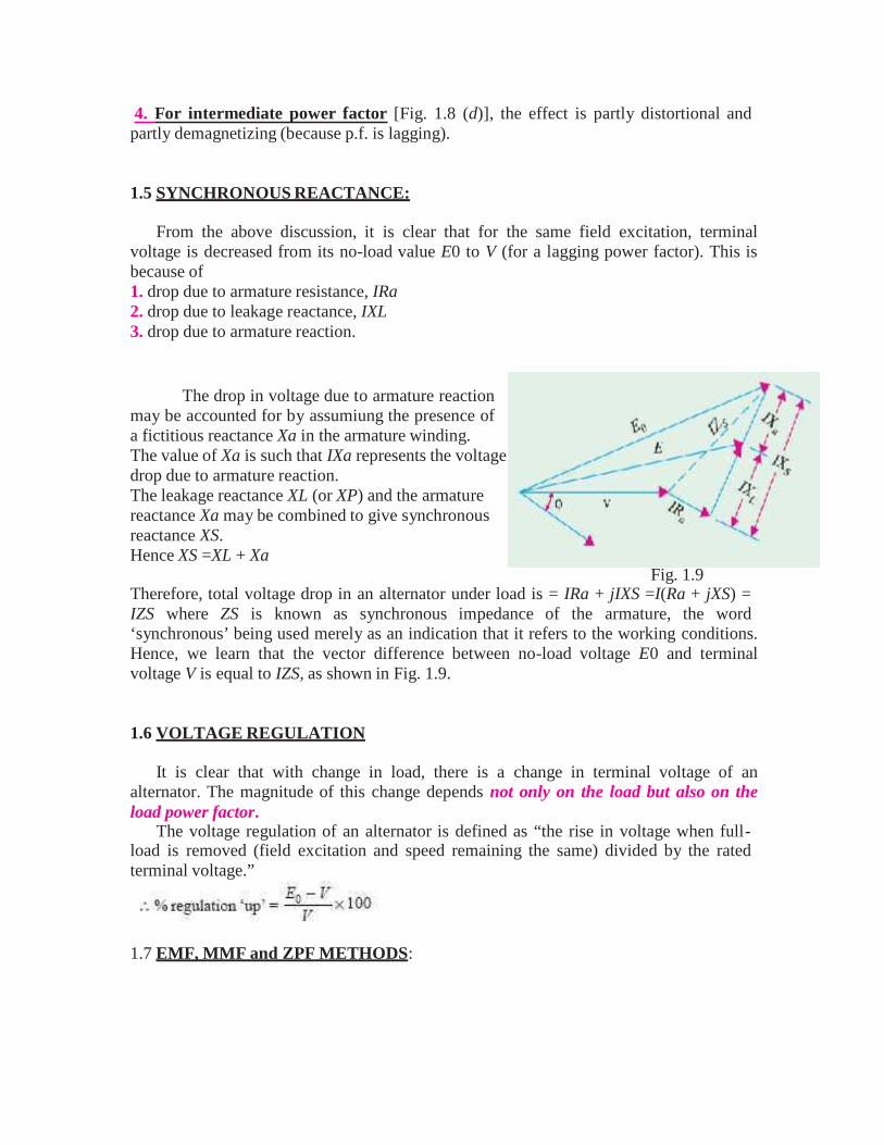
From the above discussion, it is clear that for the same field excitation, terminalvoltage is decreased from its no-load value E0 to V (for a lagging power factor). This isbecause of1. drop due to armature resistance, IRa2. drop due to leakage reactance, IXL3. drop due to armature reaction.
The drop in voltage due to armature reactionmay be accounted for by assumiung the presence ofa fictitious reactance Xa in the armature winding.The value of Xa is such that IXa represents the voltagedrop due to armature reaction.The leakage reactance XL (or XP) and the armaturereactance Xa may be combined to give synchronousreactance XS.Hence XS =XL + Xa
Fig. 1.9Therefore, total voltage drop in an alternator under load is = IRa + jIXS =I(Ra + jXS) =IZS where ZS is known as synchronous impedance of the armature, the word‘synchronous’ being used merely as an indication that it refers to the working conditions.Hence, we learn that the vector difference between no-load voltage E0 and terminalvoltage V is equal to IZS, as shown in Fig. 1.9.
1.6 VOLTAGE REGULATION
It is clear that with change in load, there is a change in terminal voltage of analternator. The magnitude of this change depends not only on the load but also on theload power factor.
The voltage regulation of an alternator is defined as “the rise in voltage when full-load is removed (field excitation and speed remaining the same) divided by the ratedterminal voltage.”
1.7 EMF, MMF and ZPF METHODS:
In the case of large machines, the cost of finding the regulation by direct loadingbecomes prohibitive. Hence, other indirect methods are used as discussed below. It willbe found that all these methods differ chiefly in the way the no-load voltage E0 is foundin each case.
1.7.1 Synchronous Impedance or E.M.F. Method. It is due to Behn Eschenberg.1.7.2. The Ampere-turn or M.M.F. Method. This method is due to Rothert.1.7.3. Zero Power Factor or Potier Method. As the name indicates, it is due to Potier.All these methods require—1. Armature (or stator) resistance Ra2. Open-circuit/No-load characteristic.3. Short-circuit characteristic (but zero power factor lagging characteristic for Potiermethod).Now, let us take up each of these methods one by one.
(i) Value of RaArmature resistance Ra per phase can be measured directly by voltmeter and
ammeter method or by using Wheatstone bridge. However, under working conditions, theeffective value of Ra is increased due to ‘skin effect’. The value of Ra so obtained isincreased by 60% or so to allow for this effect. Generally, a value 1.6 times the D.C.value is taken.
(ii) O.C. CharacteristicAs in d.c. machines, this is plotted by running the machine on no-load and by
noting the values of induced voltage and field excitation current. It is just like the B-Hcurve.
(iii) S.C. CharacteristicIt is obtained by short-circuiting the armature (i.e. stator) windings through a low-
resistance ammeter. The excitation is so adjusted as to give 1.5 to 2 times the value offull-load current. During this test, the speed which is not necessarily synchronous is keptconstant.
1.7.1 Synchronous Impedance or E.M.F. Method
Following procedural steps are involved in this method:1. O.C.C is plotted from the given data as shown in Fig. 1.10 (a).2. Similarly, S.C.C. is drawn from the data given by the short-circuit test. It is a straightline passing through the origin. Both these curves are drawn on a common field-currentbase.
Consider a field current If. The O.C. voltage corresponding to this field current isE1. When winding is short-circuited, the terminal voltage is zero. Hence, it may beassumed that the whole of this voltage E1 is being used to circulate the armature short-circuit current I1 against the synchronous impedance ZS.
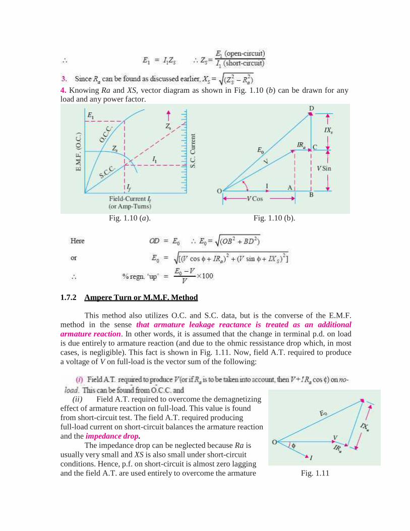
4. Knowing Ra and XS, vector diagram as shown in Fig. 1.10 (b) can be drawn for anyload and any power factor.
Fig. 1.10 (a). Fig. 1.10 (b).
1.7.2 Ampere Turn or M.M.F. Method
This method also utilizes O.C. and S.C. data, but is the converse of the E.M.F.method in the sense that armature leakage reactance is treated as an additionalarmature reaction. In other words, it is assumed that the change in terminal p.d. on loadis due entirely to armature reaction (and due to the ohmic ressistance drop which, in mostcases, is negligible). This fact is shown in Fig. 1.11. Now, field A.T. required to producea voltage of V on full-load is the vector sum of the following:
(ii) Field A.T. required to overcome the demagnetizingeffect of armature reaction on full-load. This value is foundfrom short-circuit test. The field A.T. required producingfull-load current on short-circuit balances the armature reactionand the impedance drop.
The impedance drop can be neglected because Ra isusually very small and XS is also small under short-circuitconditions. Hence, p.f. on short-circuit is almost zero laggingand the field A.T. are used entirely to overcome the armature Fig. 1.11
h
reaction which is wholly demagnetizing. In other words, the demagnetizing armatureA.T. on full-load are equal and opposite to the field A.T. required to produce full-loadcurrent on short-circuit.
Now, if the alternator, instead of being onshort-circuit, is supplying full-load current atits normal voltage and zero p.f. lagging, then totalfield A.T. required are the vector sum of(i) the field A.T. = OA necessary toproduce normal voltage (as obtained fromO.C.C.) and Fig. 1.12
(ii) the field A.T. necessary to neutralize the armature reaction AB1. The total field A.T.are represented by OB1 in Fig. 1.12 (a) and equals the vector sum of OA and AB1 If thep.f. is zero leading, the armature reaction is wholly magnetizing. Hence, in that case, thefield A.T. required is OB2 which is less than OA by the field A.T. = AB2 required toproduce full-load current on short-circuit [Fig. 1.12 (b)]
If p.f. is unity, the armature reaction is cross-magnetizing i.e. its effect isdistortional only. Hence, field A.T. required is OB3 i.e. vector sum of OA and AB3 whichis drawn at right angles to OA as in Fig. 1.12 (c).
1.7.3 Potier or Z.P.F. Method
This method is based on the separation of armature-leakage reactance drop andthe armature reaction effects. Hence, it gives more accurate results. It makes use of thefirst two methods to some extent. The experimental data required is (i) no-load curve and(ii) full-load zero power factor curve (not the short-circuit characteristic) also calledwattless load characteristic. It is the curve of terminal volts against excitation whenarmature is delivering F.L. current at zero p.f.
The reduction in voltage due to armature reaction is found from above and (ii)voltage drop due to armature leakage reactance XL (also called Potier reactance) is foundfrom both. By combining these two, E0 can be calculated. It should be noted that if wevectorially add to V the drop due to resistance and leakage reactance XL, we get E. If to Eis further added the drop due to armature reaction (assuming lagging p.f.), then we get E0The zero p.f. lagging curve can be obtained.
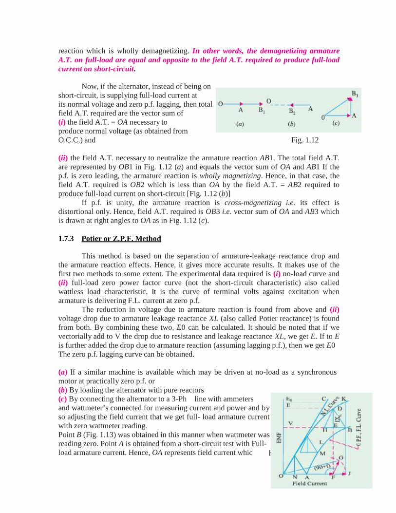
(a) If a similar machine is available which may be driven at no-load as a synchronousmotor at practically zero p.f. or(b) By loading the alternator with pure reactors(c) By connecting the alternator to a 3-Phline with ammetersand wattmeter’s connected for measuring current and power and byso adjusting the field current that we get full- load armature currentwith zero wattmeter reading.Point B (Fig. 1.13) was obtained in this manner when wattmeter wasreading zero. Point A is obtained from a short-circuit test with Full-load armature current. Hence, OA represents field current whic
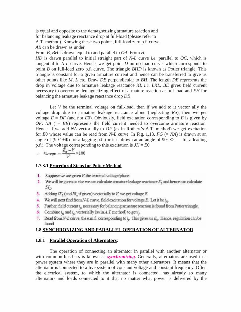
is equal and opposite to the demagnetizing armature reaction andfor balancing leakage reactance drop at full-load (please refer toA.T. method). Knowing these two points, full-load zero p.f. curveAB can be drawn as under.From B, BH is drawn equal to and parallel to OA. From H,HD is drawn parallel to initial straight part of N-L curve i.e. parallel to OC, which istangential to N-L curve. Hence, we get point D on no-load curve, which corresponds topoint B on full-load zero p.f. curve. The triangle BHD is known as Potier triangle. Thistriangle is constant for a given armature current and hence can be transferred to give usother points like M, L etc. Draw DE perpendicular to BH. The length DE represents thedrop in voltage due to armature leakage reactance XL i.e. I.XL. BE gives field currentnecessary to overcome demagnetizing effect of armature reaction at full load and EH forbalancing the armature leakage reactance drop DE.
Let V be the terminal voltage on full-load, then if we add to it vector ally thevoltage drop due to armature leakage reactance alone (neglecting Ra), then we getvoltage E = DF (and not E0). Obviously, field excitation corresponding to E is given byOF. NA ( = BE) represents the field current needed to overcome armature reaction.Hence, if we add NA vectorially to OF (as in Rothert’s A.T. method) we get excitationfor E0 whose value can be read from N-L curve. In Fig. 1.13, FG (= NA) is drawn at anangle of (90° +Φ) for a lagging p.f. (or it is drawn at an angle of 90°-Φfor a leadingp.f.). The voltage corresponding to this excitation is JK = E0
1.7.3.1 Procedural Steps for Potier Method
1.8 SYNCHRONIZING AND PARALLEL OPERATION OF ALTERNATOR
1.8.1 Parallel Operation of Alternators:
The operation of connecting an alternator in parallel with another alternator orwith common bus-bars is known as synchronizing. Generally, alternators are used in apower system where they are in parallel with many other alternators. It means that thealternator is connected to a live system of constant voltage and constant frequency. Oftenthe electrical system, to which the alternator is connected, has already so manyalternators and loads connected to it that no matter what power is delivered by the
incoming alternator, the voltage and frequency of the system remain the same. In thatcase, the alternator is said to be connected to infinite bus-bars.
It is never advisable to connect a stationary alternator to live bus-bars, because,stator induced e.m.f. being zero, a short-circuit will result. For proper synchronization ofalternators, the following three conditions must be satisfied :1. The terminal voltage (effective) of the incoming alternator must be the same as bus-barvoltage.2. The speed of the incoming machine must be such that its frequency (= PN/120) equalsbus-bar frequency.3. The phase of the alternator voltage must be identical with the phase of the bus-barvoltage. It means that the switch must be closed at (or very near) the instant the twovoltages have correct phase relationship.Condition (1) is indicated by a voltmeter, conditions (2) and (3) are indicated bysynchronizing lamps or a synchronoscope.
1.8.2 Synchronizing of Alternators:
(a) Single-phase Alternators
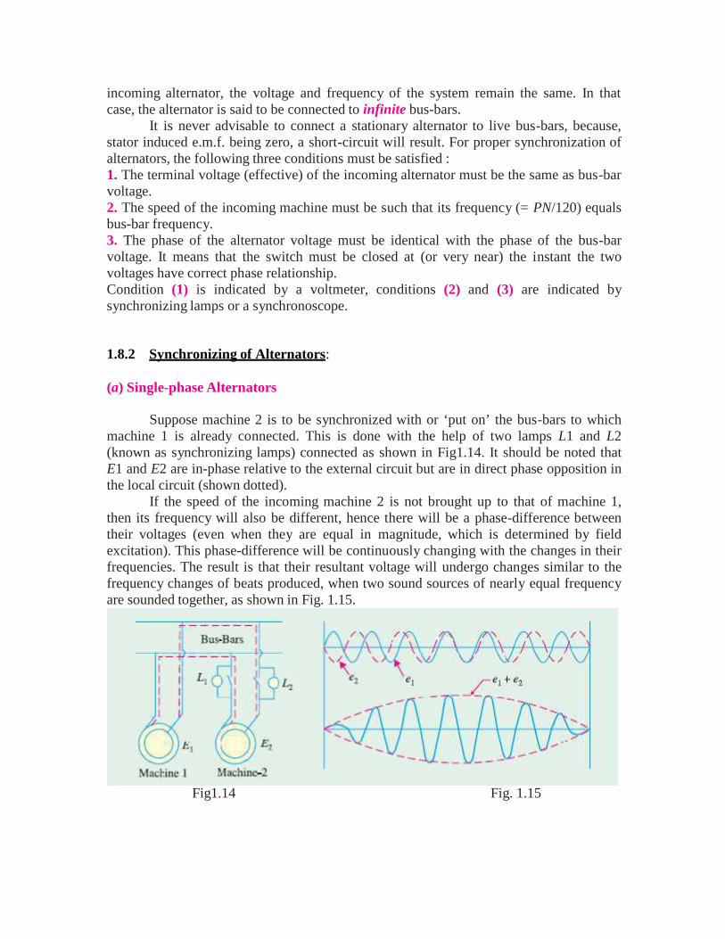
Suppose machine 2 is to be synchronized with or ‘put on’ the bus-bars to whichmachine 1 is already connected. This is done with the help of two lamps L1 and L2(known as synchronizing lamps) connected as shown in Fig1.14. It should be noted thatE1 and E2 are in-phase relative to the external circuit but are in direct phase opposition inthe local circuit (shown dotted).
If the speed of the incoming machine 2 is not brought up to that of machine 1,then its frequency will also be different, hence there will be a phase-difference betweentheir voltages (even when they are equal in magnitude, which is determined by fieldexcitation). This phase-difference will be continuously changing with the changes in theirfrequencies. The result is that their resultant voltage will undergo changes similar to thefrequency changes of beats produced, when two sound sources of nearly equal frequencyare sounded together, as shown in Fig. 1.15.
Fig1.14 Fig. 1.15
ll
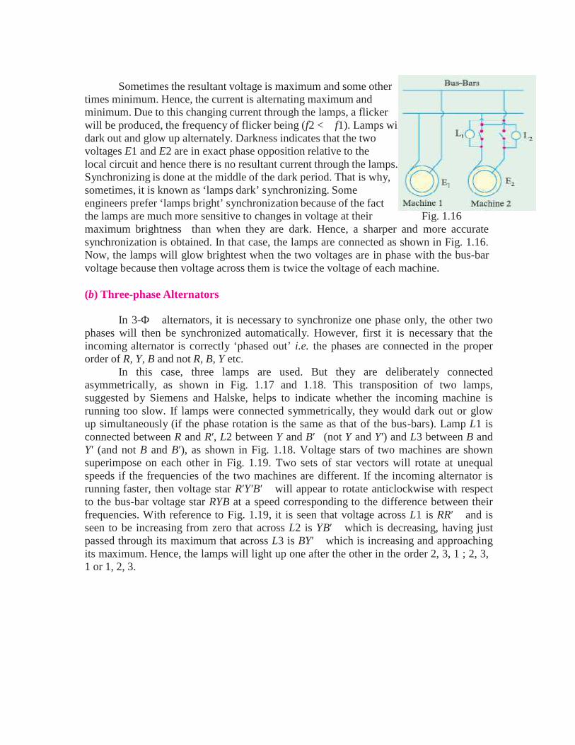
Sometimes the resultant voltage is maximum and some othertimes minimum. Hence, the current is alternating maximum andminimum. Due to this changing current through the lamps, a flickerwill be produced, the frequency of flicker being (f2 <f1). Lamps widark out and glow up alternately. Darkness indicates that the twovoltages E1 and E2 are in exact phase opposition relative to thelocal circuit and hence there is no resultant current through the lamps.Synchronizing is done at the middle of the dark period. That is why,sometimes, it is known as ‘lamps dark’ synchronizing. Someengineers prefer ‘lamps bright’ synchronization because of the factthe lamps are much more sensitive to changes in voltage at their Fig. 1.16maximum brightness than when they are dark. Hence, a sharper and more accuratesynchronization is obtained. In that case, the lamps are connected as shown in Fig. 1.16.Now, the lamps will glow brightest when the two voltages are in phase with the bus-barvoltage because then voltage across them is twice the voltage of each machine.
(b) Three-phase Alternators
In 3-Φ alternators, it is necessary to synchronize one phase only, the other twophases will then be synchronized automatically. However, first it is necessary that theincoming alternator is correctly ‘phased out’ i.e. the phases are connected in the properorder of R, Y, B and not R, B, Y etc.
In this case, three lamps are used. But they are deliberately connectedasymmetrically, as shown in Fig. 1.17 and 1.18. This transposition of two lamps,suggested by Siemens and Halske, helps to indicate whether the incoming machine isrunning too slow. If lamps were connected symmetrically, they would dark out or glowup simultaneously (if the phase rotation is the same as that of the bus-bars). Lamp L1 isconnected between R and R′, L2 between Y and B′(not Y and Y′) and L3 between B andY′ (and not B and B′), as shown in Fig. 1.18. Voltage stars of two machines are shownsuperimpose on each other in Fig. 1.19. Two sets of star vectors will rotate at unequalspeeds if the frequencies of the two machines are different. If the incoming alternator isrunning faster, then voltage star R′Y′B′ will appear to rotate anticlockwise with respectto the bus-bar voltage star RYB at a speed corresponding to the difference between theirfrequencies. With reference to Fig. 1.19, it is seen that voltage across L1 is RR′and isseen to be increasing from zero that across L2 is YB′ which is decreasing, having justpassed through its maximum that across L3 is BY′which is increasing and approachingits maximum. Hence, the lamps will light up one after the other in the order 2, 3, 1 ; 2, 3,1 or 1, 2, 3.
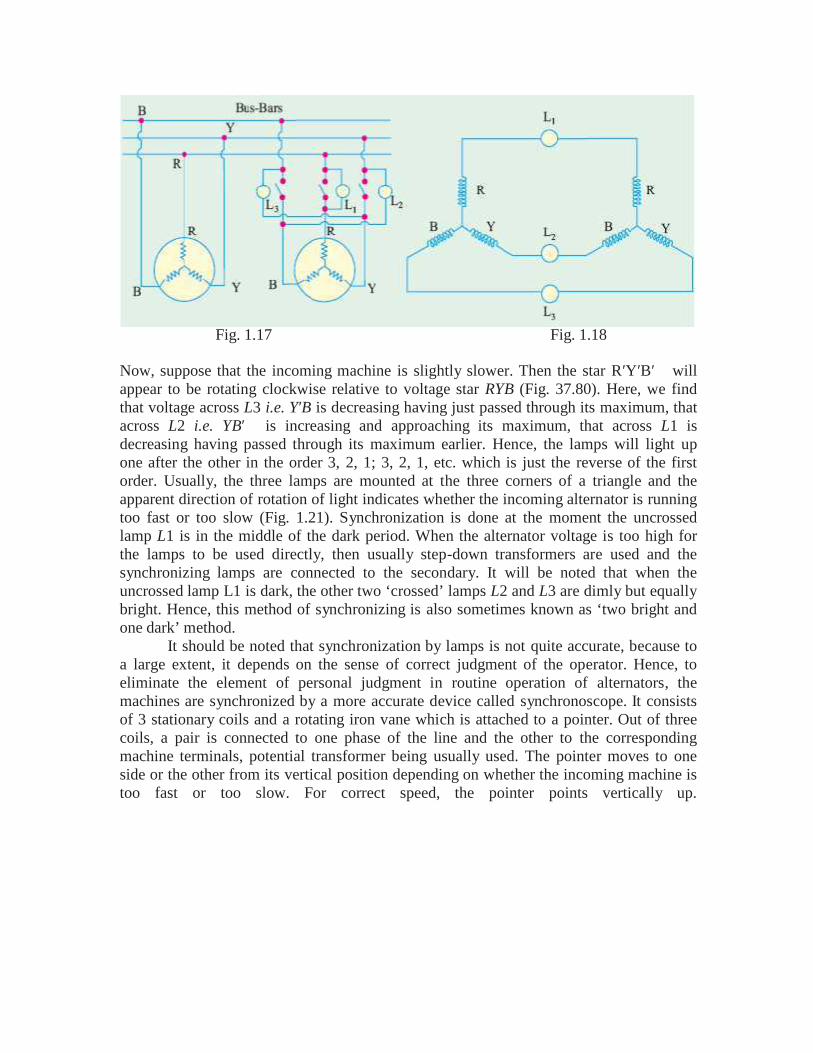
Fig. 1.17 Fig. 1.18
Now, suppose that the incoming machine is slightly slower. Then the star R′Y′B′willappear to be rotating clockwise relative to voltage star RYB (Fig. 37.80). Here, we findthat voltage across L3 i.e. Y′B is decreasing having just passed through its maximum, thatacross L2 i.e. YB′ is increasing and approaching its maximum, that across L1 isdecreasing having passed through its maximum earlier. Hence, the lamps will light upone after the other in the order 3, 2, 1; 3, 2, 1, etc. which is just the reverse of the firstorder. Usually, the three lamps are mounted at the three corners of a triangle and theapparent direction of rotation of light indicates whether the incoming alternator is runningtoo fast or too slow (Fig. 1.21). Synchronization is done at the moment the uncrossedlamp L1 is in the middle of the dark period. When the alternator voltage is too high forthe lamps to be used directly, then usually step-down transformers are used and thesynchronizing lamps are connected to the secondary. It will be noted that when theuncrossed lamp L1 is dark, the other two ‘crossed’ lamps L2 and L3 are dimly but equallybright. Hence, this method of synchronizing is also sometimes known as ‘two bright andone dark’ method.
It should be noted that synchronization by lamps is not quite accurate, because toa large extent, it depends on the sense of correct judgment of the operator. Hence, toeliminate the element of personal judgment in routine operation of alternators, themachines are synchronized by a more accurate device called synchronoscope. It consistsof 3 stationary coils and a rotating iron vane which is attached to a pointer. Out of threecoils, a pair is connected to one phase of the line and the other to the correspondingmachine terminals, potential transformer being usually used. The pointer moves to oneside or the other from its vertical position depending on whether the incoming machine istoo fast or too slow. For correct speed, the pointer points vertically up.
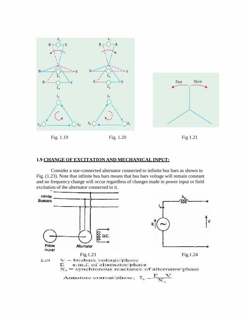
Fig. 1.19 Fig. 1.20 Fig 1.21
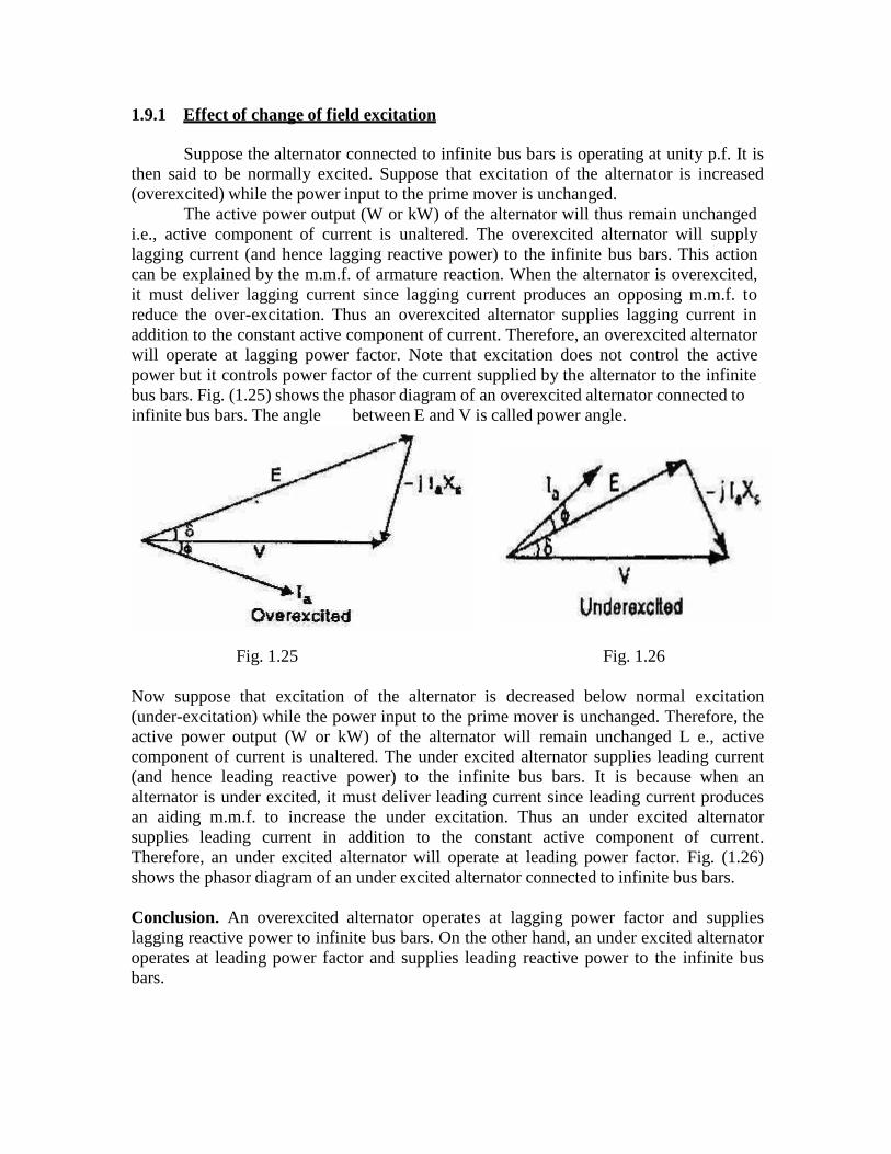
1.9 CHANGE OF EXCITATION AND MECHANICAL INPUT:
Consider a star-connected alternator connected to infinite bus bars as shown inFig. (1.23). Note that infinite bus bars means that bus bars voltage will remain constantand no frequency change will occur regardless of changes made in power input or fieldexcitation of the alternator connected to it.
Fig.1.23 Fig.1.24
1.10 Blondel’ Theory1.11 Determination of Xd and Xq using slip
1.9.1 Effect of change of field excitation
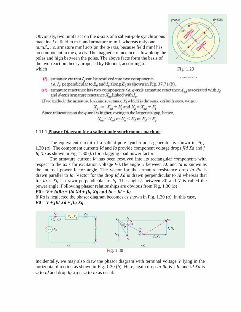
Suppose the alternator connected to infinite bus bars is operating at unity p.f. It isthen said to be normally excited. Suppose that excitation of the alternator is increased(overexcited) while the power input to the prime mover is unchanged.
The active power output (W or kW) of the alternator will thus remain unchangedi.e., active component of current is unaltered. The overexcited alternator will supplylagging current (and hence lagging reactive power) to the infinite bus bars. This actioncan be explained by the m.m.f. of armature reaction. When the alternator is overexcited,it must deliver lagging current since lagging current produces an opposing m.m.f. toreduce the over-excitation. Thus an overexcited alternator supplies lagging current inaddition to the constant active component of current. Therefore, an overexcited alternatorwill operate at lagging power factor. Note that excitation does not control the activepower but it controls power factor of the current supplied by the alternator to the infinitebus bars. Fig. (1.25) shows the phasor diagram of an overexcited alternator connected toinfinite bus bars. The anglebetween E and V is called power angle.
Fig. 1.25 Fig. 1.26
Now suppose that excitation of the alternator is decreased below normal excitation(under-excitation) while the power input to the prime mover is unchanged. Therefore, theactive power output (W or kW) of the alternator will remain unchanged L e., activecomponent of current is unaltered. The under excited alternator supplies leading current(and hence leading reactive power) to the infinite bus bars. It is because when analternator is under excited, it must deliver leading current since leading current producesan aiding m.m.f. to increase the under excitation. Thus an under excited alternatorsupplies leading current in addition to the constant active component of current.Therefore, an under excited alternator will operate at leading power factor. Fig. (1.26)shows the phasor diagram of an under excited alternator connected to infinite bus bars.
Conclusion. An overexcited alternator operates at lagging power factor and supplieslagging reactive power to infinite bus bars. On the other hand, an under excited alternatoroperates at leading power factor and supplies leading reactive power to the infinite busbars.

1.10.2 Effect of change in mechanical input
Suppose the alternator is delivering power to infinite bus bars under stableconditions so that a certain power angle exists between V and E and E leads V. Thephasor diagram for this situation is depicted in Fig. (1.27). Now, suppose that excitationof the alternator is kept constant and power input to its prime mover is increased. Theincrease in power input would tend to accelerate the rotor and £ would move furtherahead of V i.e., angle increases. Increasing results in larger Ia (= E V/Xs) andlower as shown in Fig. (1.28). Therefore, the alternator will deliver more active powerto the infinite bus bars. The angle assumes such a value that current Ia has an activepower component corresponding to the input: Equilibrium will be re-established at thespeed corresponding to the frequency of the infinite bus bars with a larger . Fig. (1.28) isdrawn for the same D.C. field excitation and, therefore, the same E as Fig. (1.27) but theactive power output (= VIc cos ) is greater than for the condition of Fig. (1.27) andincrease in 6 has caused the alternator to deliver additional active power to the bus bars.Note that mechanical input to the prime mover cannot change the speed of the alternatorbecause it is fixed by system frequency. Increasing mechanical input increases the speedof the alternator temporarily till such time the power angle increases to a valuerequired for stable operation. Once this condition is reached, the alternator continues torun at synchronous speed.
Fig. 1.27 Fig. 1.28
Conclusion. Increasing the mechanical input power to the prime mover will not changethe speed ultimately but will increase the power angle . As a result, the change ofdriving torque controls the output kW and not the KVAR. When this change takes place,the power factor of the machine is practically not affected.
1.11 Blondel’s Theory (Operation of a Salient Pole Synchronous Machine):
A multipolar machine with cylindrical rotor has a uniform air-gap, because ofwhich its reactance remains the same, irrespective of the spatial position of the rotor.However, a synchronous machine with salient or projecting poles has non-uniform air-gap due to which its reactance varies with the rotor position. Consequently, a cylindricalrotor machine possesses one axis of symmetry (pole axis or direct axis) whereas salient-pole machine possesses two axes of geometric symmetry (i) field poles axis, called directaxis or d-axis and (ii) axis passing through the centre of the inter polar space, called thequadrature axis or q-axis, as shown in Fig. 1.29.
Obviously, two mmfs act on the d-axis of a salient-pole synchronousmachine i.e. field m.m.f. and armature m.m.f. whereas only onem.m.f., i.e. armature mmf acts on the q-axis, because field mmf hasno component in the q-axis. The magnetic reluctance is low along thepoles and high between the poles. The above facts form the basis ofthe two-reaction theory proposed by Blondel, according towhich Fig. 1.29
1.11.1 Phasor Diagram for a salient pole synchronous machine:
The equivalent circuit of a salient-pole synchronous generator is shown in Fig.1.30 (a). The component currents Id and Iq provide component voltage drops jId Xd and jIq Xq as shown in Fig. 1.30 (b) for a lagging load power factor.
The armature current Ia has been resolved into its rectangular components withrespect to the axis for excitation voltage E0.The angle ψ between E0 and Ia is known asthe internal power factor angle. The vector for the armature resistance drop Ia Ra isdrawn parallel to Ia. Vector for the drop Id Xd is drawn perpendicular to Id whereas thatfor Iq × Xq is drawn perpendicular to Iq. The angle δ between E0 and V is called thepower angle. Following phasor relationships are obvious from Fig. 1.30 (b)E0 = V + IaRa + jId Xd + jIq Xq and Ia = Id + IqIf Ra is neglected the phasor diagram becomes as shown in Fig. 1.30 (a). In this case,E0 = V + jId Xd + jIq Xq
Fig. 1.30
Incidentally, we may also draw the phasor diagram with terminal voltage V lying in thehorizontal direction as shown in Fig. 1.30 (b). Here, again drop Ia Ra is || Ia and Id Xd is to Id and drop Iq Xq is to Iq as usual.
UNIT II
SYNCHRONOUS MOTOR
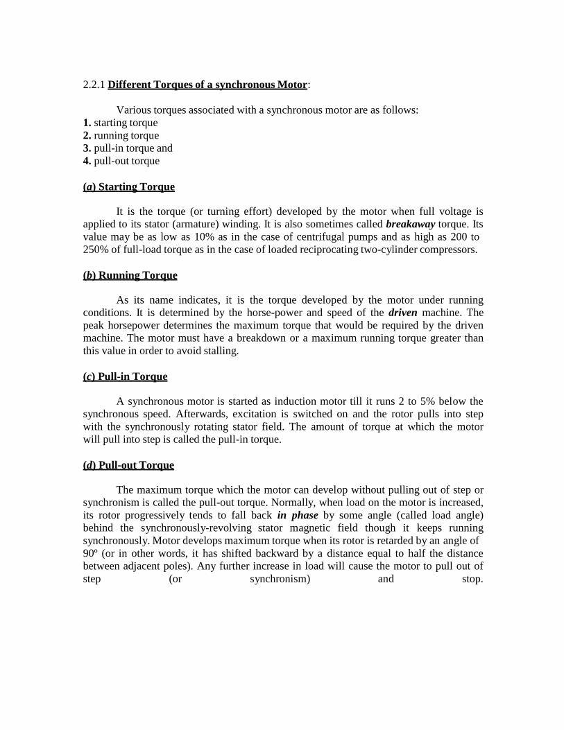
Synchronous Motor—General
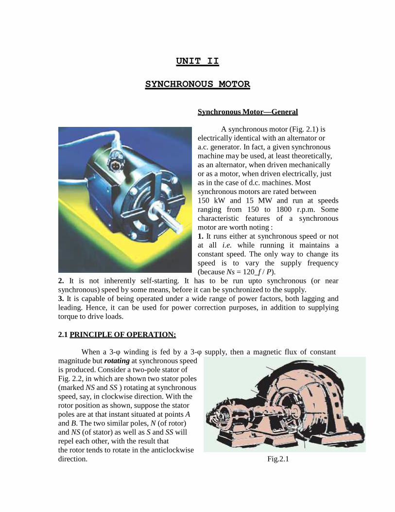
A synchronous motor (Fig. 2.1) iselectrically identical with an alternator ora.c. generator. In fact, a given synchronousmachine may be used, at least theoretically,as an alternator, when driven mechanicallyor as a motor, when driven electrically, justas in the case of d.c. machines. Mostsynchronous motors are rated between150 kW and 15 MW and run at speedsranging from 150 to 1800 r.p.m. Somecharacteristic features of a synchronousmotor are worth noting :1. It runs either at synchronous speed or notat all i.e. while running it maintains aconstant speed. The only way to change itsspeed is to vary the supply frequency(because Ns = 120_f / P).
2. It is not inherently self-starting. It has to be run upto synchronous (or nearsynchronous) speed by some means, before it can be synchronized to the supply.3. It is capable of being operated under a wide range of power factors, both lagging andleading. Hence, it can be used for power correction purposes, in addition to supplyingtorque to drive loads.
2.1 PRINCIPLE OF OPERATION:
When a 3-φ winding is fed by a 3-φ supply, then a magnetic flux of constantmagnitude but rotating at synchronous speedis produced. Consider a two-pole stator ofFig. 2.2, in which are shown two stator poles(marked NS and SS ) rotating at synchronousspeed, say, in clockwise direction. With therotor position as shown, suppose the statorpoles are at that instant situated at points Aand B. The two similar poles, N (of rotor)and NS (of stator) as well as S and SS willrepel each other, with the result thatthe rotor tends to rotate in the anticlockwisedirection. Fig.2.1
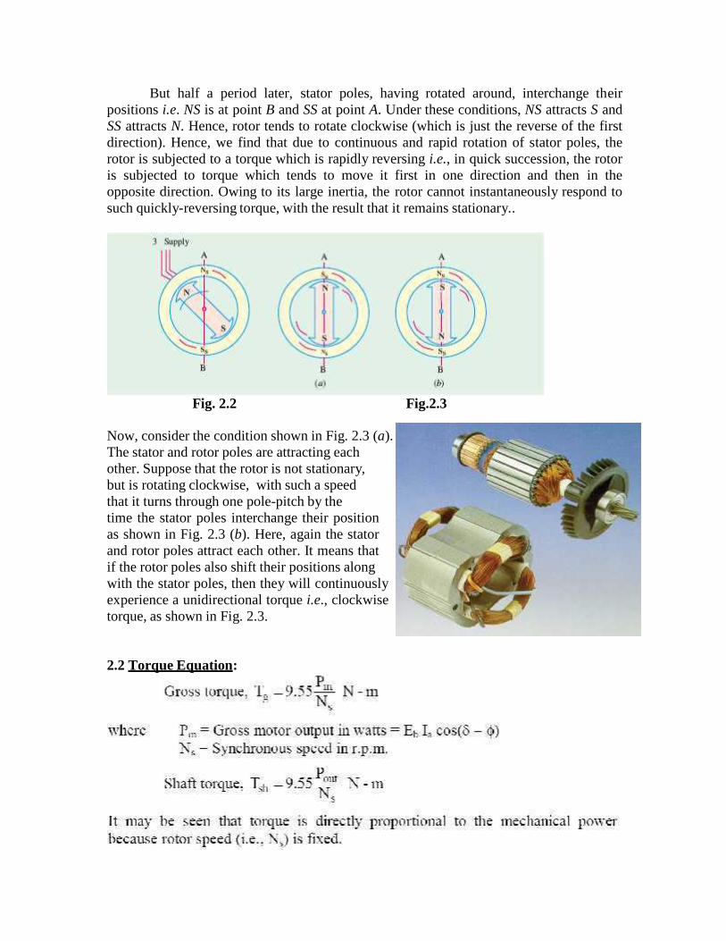
But half a period later, stator poles, having rotated around, interchange theirpositions i.e. NS is at point B and SS at point A. Under these conditions, NS attracts S andSS attracts N. Hence, rotor tends to rotate clockwise (which is just the reverse of the firstdirection). Hence, we find that due to continuous and rapid rotation of stator poles, therotor is subjected to a torque which is rapidly reversing i.e., in quick succession, the rotoris subjected to torque which tends to move it first in one direction and then in theopposite direction. Owing to its large inertia, the rotor cannot instantaneously respond tosuch quickly-reversing torque, with the result that it remains stationary..
Fig. 2.2 Fig.2.3
Now, consider the condition shown in Fig. 2.3 (a).The stator and rotor poles are attracting eachother. Suppose that the rotor is not stationary,but is rotating clockwise, with such a speedthat it turns through one pole-pitch by thetime the stator poles interchange their positionas shown in Fig. 2.3 (b). Here, again the statorand rotor poles attract each other. It means thatif the rotor poles also shift their positions alongwith the stator poles, then they will continuouslyexperience a unidirectional torque i.e., clockwisetorque, as shown in Fig. 2.3.
2.2 Torque Equation:
2.2.1 Different Torques of a synchronous Motor:
Various torques associated with a synchronous motor are as follows:1. starting torque2. running torque3. pull-in torque and4. pull-out torque
(a) Starting Torque
It is the torque (or turning effort) developed by the motor when full voltage isapplied to its stator (armature) winding. It is also sometimes called breakaway torque. Itsvalue may be as low as 10% as in the case of centrifugal pumps and as high as 200 to250% of full-load torque as in the case of loaded reciprocating two-cylinder compressors.
(b) Running Torque
As its name indicates, it is the torque developed by the motor under runningconditions. It is determined by the horse-power and speed of the driven machine. Thepeak horsepower determines the maximum torque that would be required by the drivenmachine. The motor must have a breakdown or a maximum running torque greater thanthis value in order to avoid stalling.
(c) Pull-in Torque
A synchronous motor is started as induction motor till it runs 2 to 5% below thesynchronous speed. Afterwards, excitation is switched on and the rotor pulls into stepwith the synchronously rotating stator field. The amount of torque at which the motorwill pull into step is called the pull-in torque.
(d) Pull-out Torque
The maximum torque which the motor can develop without pulling out of step orsynchronism is called the pull-out torque. Normally, when load on the motor is increased,its rotor progressively tends to fall back in phase by some angle (called load angle)behind the synchronously-revolving stator magnetic field though it keeps runningsynchronously. Motor develops maximum torque when its rotor is retarded by an angle of90º (or in other words, it has shifted backward by a distance equal to half the distancebetween adjacent poles). Any further increase in load will cause the motor to pull out ofstep (or synchronism) and stop.
2.3 STARTING METHODS:
The rotor (which is as yet unexcited) is speeded up to synchronous / near synchronousspeed by some arrangement and then excited by the d.c. source. The moment this (near)synchronously rotating rotor is excited, it is magnetically locked into position with thestator i.e., the rotor poles are engaged with the stator poles and both run synchronously inthe same direction. It is because of this interlocking of stator and rotor poles that themotor has either to run synchronously or not at all. The synchronous speed is given bythe usual relation NS = 120 f / P.
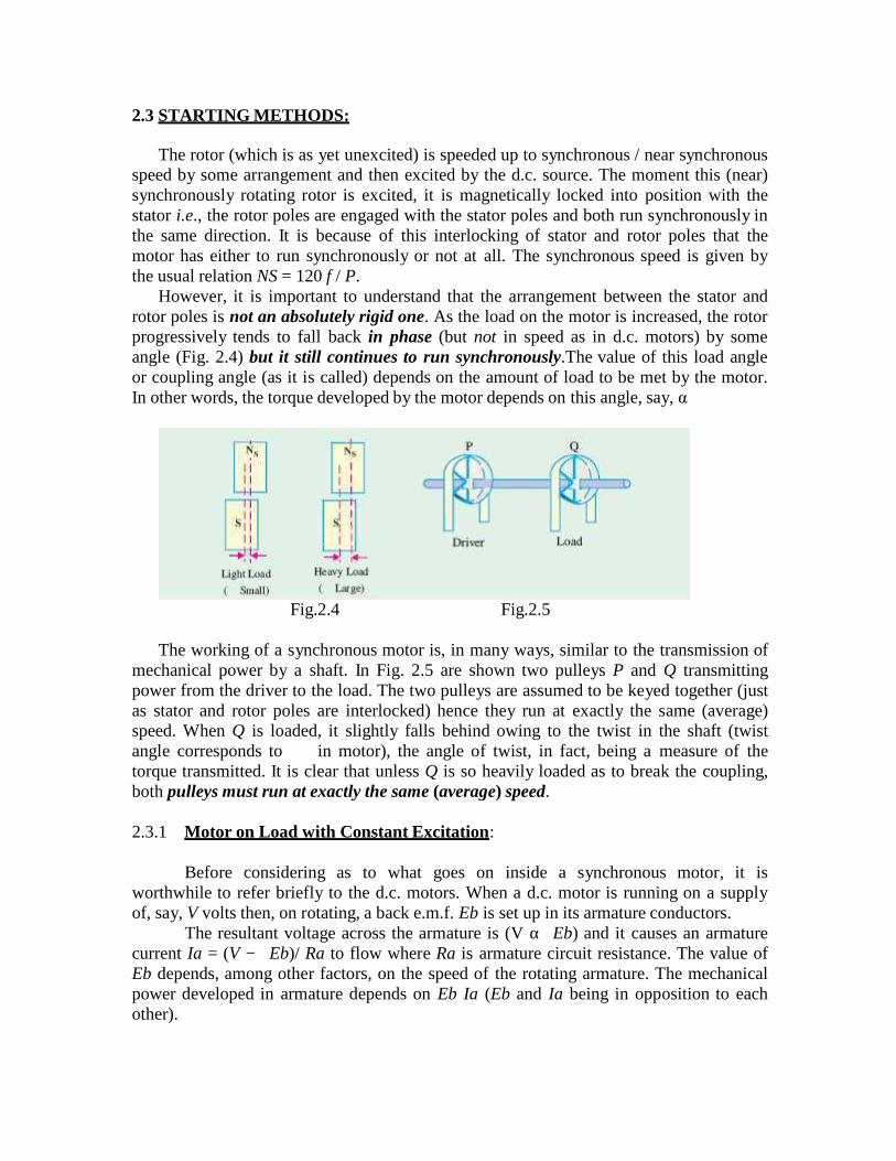
However, it is important to understand that the arrangement between the stator androtor poles is not an absolutely rigid one. As the load on the motor is increased, the rotorprogressively tends to fall back in phase (but not in speed as in d.c. motors) by someangle (Fig. 2.4) but it still continues to run synchronously.The value of this load angleor coupling angle (as it is called) depends on the amount of load to be met by the motor.In other words, the torque developed by the motor depends on this angle, say, α
Fig.2.4 Fig.2.5
The working of a synchronous motor is, in many ways, similar to the transmission ofmechanical power by a shaft. In Fig. 2.5 are shown two pulleys P and Q transmittingpower from the driver to the load. The two pulleys are assumed to be keyed together (justas stator and rotor poles are interlocked) hence they run at exactly the same (average)speed. When Q is loaded, it slightly falls behind owing to the twist in the shaft (twistangle corresponds to in motor), the angle of twist, in fact, being a measure of thetorque transmitted. It is clear that unless Q is so heavily loaded as to break the coupling,both pulleys must run at exactly the same (average) speed.
2.3.1 Motor on Load with Constant Excitation:
Before considering as to what goes on inside a synchronous motor, it isworthwhile to refer briefly to the d.c. motors. When a d.c. motor is running on a supplyof, say, V volts then, on rotating, a back e.m.f. Eb is set up in its armature conductors.
The resultant voltage across the armature is (V αEb) and it causes an armaturecurrent Ia = (V −Eb)/ Ra to flow where Ra is armature circuit resistance. The value ofEb depends, among other factors, on the speed of the rotating armature. The mechanicalpower developed in armature depends on Eb Ia (Eb and Ia being in opposition to eachother).

Similarly, in a synchronous machine, a back e.m.f. Eb is set up in the armature(stator) by the rotor flux which opposes the applied voltage V. This back e.m.f. dependson rotor excitation only (and not on speed, as in d.c. motors). The net voltage in armature(stator) is the vector difference (not arithmetical, as in d.c. motors) of V and Eb.Armature current is obtained by dividing this vector difference of voltages by armatureimpedance (not resistance as in d.c. machines).
Fig. 2.6 Fig. 2.7 Fig. 2.8
Fig. 2.6 shows the condition when the motor (properly synchronized to the supply) isrunning on no-load and has no losses and is having field excitation which makes Eb = V.It is seen that vector difference of Eb and V is zero and so is the armature current. Motorintake is zero, as there is neither load nor losses to be met by it. In other words, the motorjust floats. If motor is on no-load, but it has losses, then the vector for Eb falls back(vectors are rotating anti-clockwise) by a certain small angle (Fig. 2.7), so that aresultant voltage ER and hence current Ia is brought into existence, which supplies losses.If, now, the motor is loaded, then its rotor will further fall back in phase by a greatervalue of angle αcalled the load angle or coupling angle (corresponding to the twistin the shaft of the pulleys). The resultant voltage ER is increased and motor draws anincreased armature current (Fig. 2.8), though at a slightly decreased power factor.
2.4 OPERATION ON INFINITE BUS BAR
In order to simplify the ideas as much as possible the resistance of the generator willbe neglected; in practice this assumption is usually reasonable. Figure 1 (a) shows theschematic diagram of a machine connected to an infinite bus bar along with thecorresponding phasor diagram.
2.5 V AND INVERTED V CURVES:
The value of excitation for which back e.m.f. Eb is equal (in magnitude) to appliedvoltage V is known as 100% excitation. We will now discuss what happens when motor
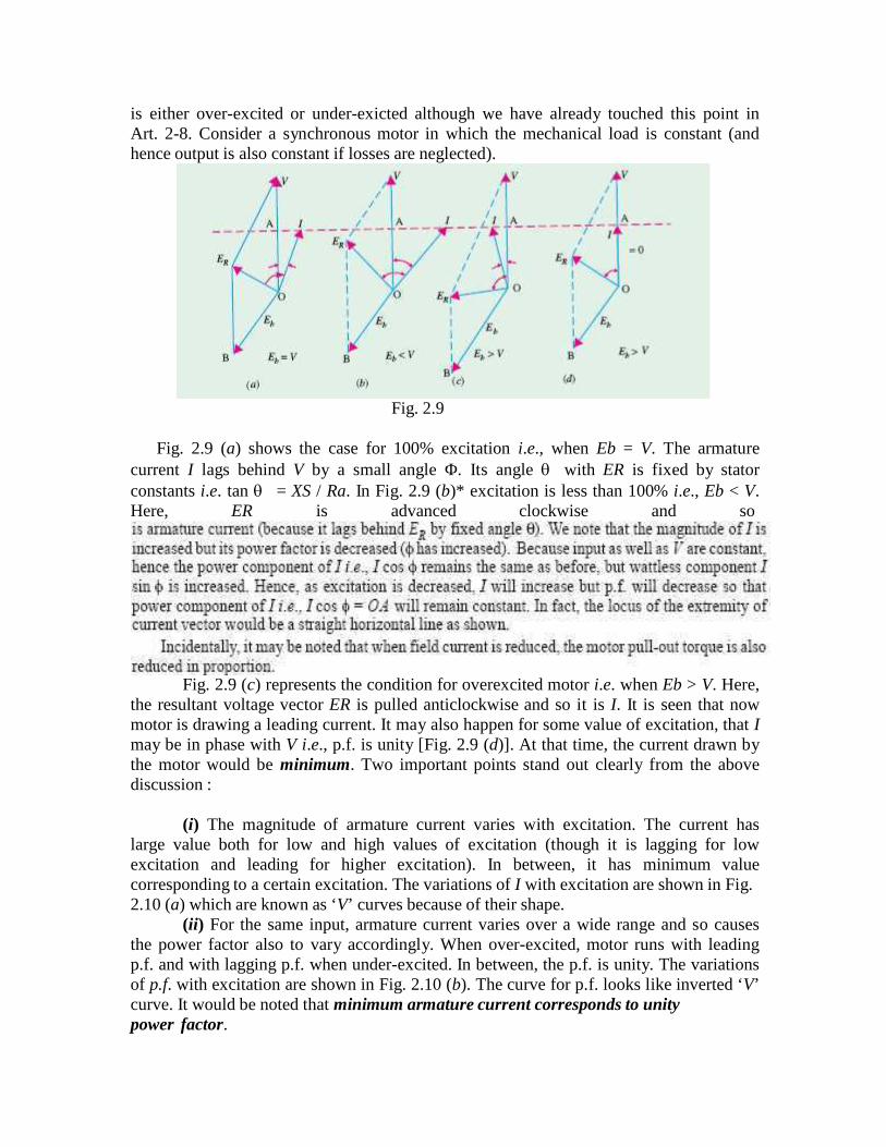
is either over-excited or under-exicted although we have already touched this point inArt. 2-8. Consider a synchronous motor in which the mechanical load is constant (andhence output is also constant if losses are neglected).
Fig. 2.9
Fig. 2.9 (a) shows the case for 100% excitation i.e., when Eb = V. The armaturecurrent I lags behind V by a small angle Φ. Its angle with ER is fixed by statorconstants i.e. tan = XS / Ra. In Fig. 2.9 (b)* excitation is less than 100% i.e., Eb < V.Here, ER is advanced clockwise and so
Fig. 2.9 (c) represents the condition for overexcited motor i.e. when Eb > V. Here,the resultant voltage vector ER is pulled anticlockwise and so it is I. It is seen that nowmotor is drawing a leading current. It may also happen for some value of excitation, that Imay be in phase with V i.e., p.f. is unity [Fig. 2.9 (d)]. At that time, the current drawn bythe motor would be minimum. Two important points stand out clearly from the abovediscussion :
(i) The magnitude of armature current varies with excitation. The current haslarge value both for low and high values of excitation (though it is lagging for lowexcitation and leading for higher excitation). In between, it has minimum valuecorresponding to a certain excitation. The variations of I with excitation are shown in Fig.2.10 (a) which are known as ‘V’ curves because of their shape.
(ii) For the same input, armature current varies over a wide range and so causesthe power factor also to vary accordingly. When over-excited, motor runs with leadingp.f. and with lagging p.f. when under-excited. In between, the p.f. is unity. The variationsof p.f. with excitation are shown in Fig. 2.10 (b). The curve for p.f. looks like inverted ‘V’curve. It would be noted that minimum armature current corresponds to unitypower factor.
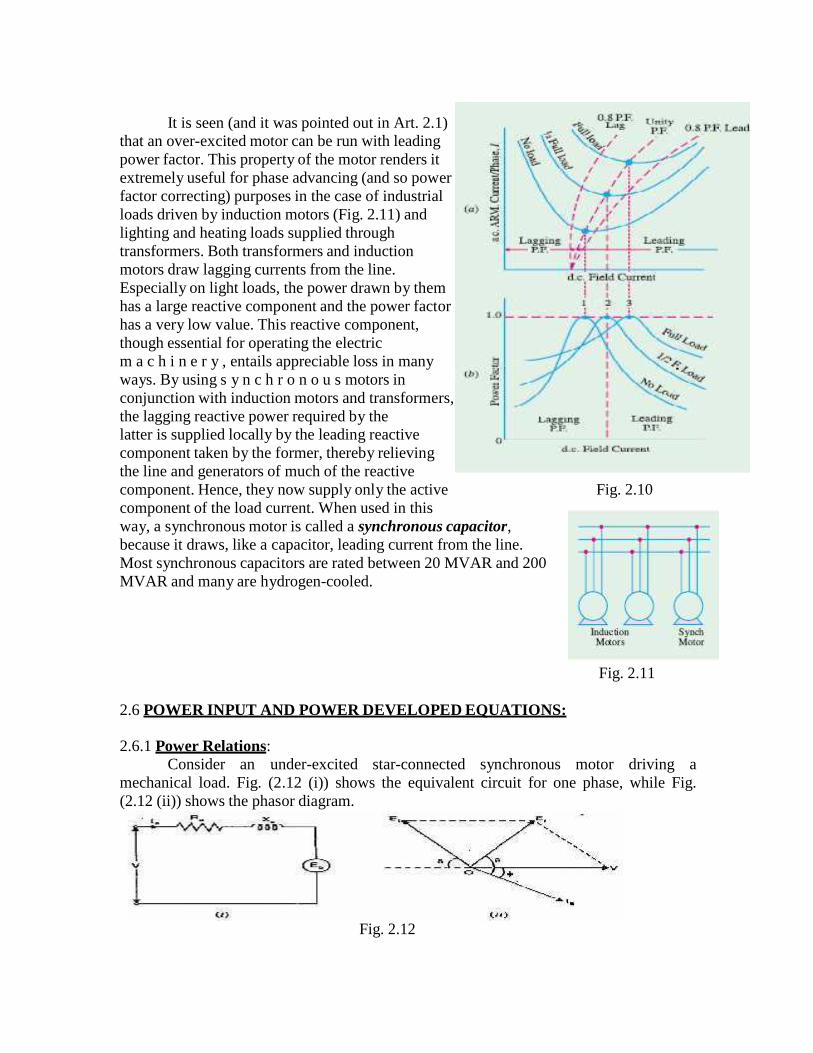
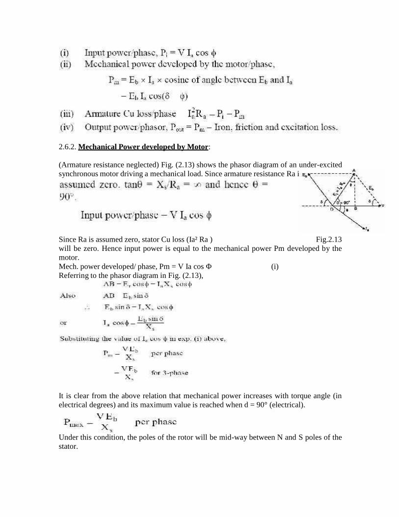
It is seen (and it was pointed out in Art. 2.1)that an over-excited motor can be run with leadingpower factor. This property of the motor renders itextremely useful for phase advancing (and so powerfactor correcting) purposes in the case of industrialloads driven by induction motors (Fig. 2.11) andlighting and heating loads supplied throughtransformers. Both transformers and inductionmotors draw lagging currents from the line.Especially on light loads, the power drawn by themhas a large reactive component and the power factorhas a very low value. This reactive component,though essential for operating the electricm a c h i n e r y , entails appreciable loss in manyways. By using s y n c h r o n o u s motors inconjunction with induction motors and transformers,the lagging reactive power required by thelatter is supplied locally by the leading reactivecomponent taken by the former, thereby relievingthe line and generators of much of the reactivecomponent. Hence, they now supply only the active Fig. 2.10component of the load current. When used in thisway, a synchronous motor is called a synchronous capacitor,because it draws, like a capacitor, leading current from the line.Most synchronous capacitors are rated between 20 MVAR and 200MVAR and many are hydrogen-cooled.
Fig. 2.11
2.6 POWER INPUT AND POWER DEVELOPED EQUATIONS:
2.6.1 Power Relations:Consider an under-excited star-connected synchronous motor driving a
mechanical load. Fig. (2.12 (i)) shows the equivalent circuit for one phase, while Fig.(2.12 (ii)) shows the phasor diagram.
Fig. 2.12
s
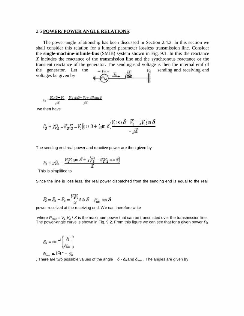
2.6.2. Mechanical Power developed by Motor:
(Armature resistance neglected) Fig. (2.13) shows the phasor diagram of an under-excitedsynchronous motor driving a mechanical load. Since armature resistance Ra i
Since Ra is assumed zero, stator Cu loss (Ia² Ra ) Fig.2.13will be zero. Hence input power is equal to the mechanical power Pm developed by themotor.Mech. power developed/ phase, Pm = V Ia cos Φ (i)Referring to the phasor diagram in Fig. (2.13),
It is clear from the above relation that mechanical power increases with torque angle (inelectrical degrees) and its maximum value is reached when d = 90° (electrical).
Under this condition, the poles of the rotor will be mid-way between N and S poles of thestator.
2.6 POWER/ POWER ANGLE RELATIONS:
The power-angle relationship has been discussed in Section 2.4.3. In this section weshall consider this relation for a lumped parameter lossless transmission line. Considerthe single-machine-infinite-bus (SMIB) system shown in Fig. 9.1. In this the reactanceX includes the reactance of the transmission line and the synchronous reactance or thetransient reactance of the generator. The sending end voltage is then the internal emf ofthe generator. Let the sending and receiving endvoltages be given by
we then have
The sending end real power and reactive power are then given by
This is simplified to
Since the line is loss less, the real power dispatched from the sending end is equal to the real
power received at the receiving end. We can therefore write
where Pmax = V1 V2 / X is the maximum power that can be transmitted over the transmission line.The power-angle curve is shown in Fig. 9.2. From this figure we can see that for a given power P0
. There are two possible values of the angle δ - δ0 and δmax . The angles are given by
If now, there is sudden decrease in thed up or advanced to a new value of
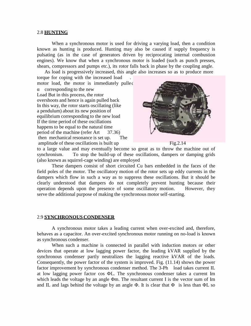
2.8 HUNTING
When a synchronous motor is used for driving a varying load, then a conditionknown as hunting is produced. Hunting may also be caused if supply frequency ispulsating (as in the case of generators driven by reciprocating internal combustionengines). We know that when a synchronous motor is loaded (such as punch presses,shears, compressors and pumps etc.), its rotor falls back in phase by the coupling angle.As load is progressively increased, this angle also increases so as to produce moretorque for coping with the increased load.motor load, the motor is immediately pulleαcorresponding to the newLoad But in this process, the rotorovershoots and hence is again pulled backIn this way, the rotor starts oscillating (likea pendulum) about its new position ofequilibrium corresponding to the new loadIf the time period of these oscillationshappens to be equal to the natural timeperiod of the machine (refer Art37.36)then mechanical resonance is set up.Theamplitude of these oscillations is built up Fig.2.14
to a large value and may eventually become so great as to throw the machine out ofsynchronism. To stop the build-up of these oscillations, dampers or damping grids(also known as squirrel-cage winding) are employed
These dampers consist of short circuited Cu bars embedded in the faces of thefield poles of the motor. The oscillatory motion of the rotor sets up eddy currents in thedampers which flow in such a way as to suppress these oscillations. But it should beclearly understood that dampers do not completely prevent hunting because theiroperation depends upon the presence of some oscillatory motion. However, theyserve the additional purpose of making the synchronous motor self-starting.
2.9 SYNCHRONOUS CONDENSER
A synchronous motor takes a leading current when over-excited and, therefore,behaves as a capacitor. An over-excited synchronous motor running on no-load is knownas synchronous condenser.
When such a machine is connected in parallel with induction motors or otherdevices that operate at low lagging power factor, the leading kVAR supplied by thesynchronous condenser partly neutralizes the lagging reactive kVAR of the loads.Consequently, the power factor of the system is improved. Fig. (11.14) shows the powerfactor improvement by synchronous condenser method. The 3-Ph load takes current ILat low lagging power factor cos ΦL. The synchronous condenser takes a current Imwhich leads the voltage by an angle Φm. The resultant current I is the vector sum of Imand IL and lags behind the voltage by an angle Φ. It is clear that Φis less than ΦL so
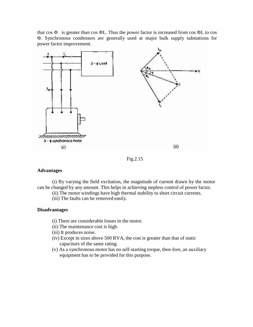
that cos Φis greater than cos ΦL. Thus the power factor is increased from cos ΦL to cosΦ. Synchronous condensers are generally used at major bulk supply substations forpower factor improvement.
Fig.2.15
Advantages
(i) By varying the field excitation, the magnitude of current drawn by the motorcan be changed by any amount. This helps in achieving stepless control of power factor.
(ii) The motor windings have high thermal stability to short circuit currents.(iii) The faults can be removed easily.
Disadvantages
(i) There are considerable losses in the motor.(ii) The maintenance cost is high.(iii) It produces noise.(iv) Except in sizes above 500 RVA, the cost is greater than that of static
capacitors of the same rating.(v) As a synchronous motor has no self-starting torque, then-fore, an auxiliary
equipment has to be provided for this purpose.
2.10 APPLICATIONS:
(i) Synchronous motors are particularly attractive for low speeds (< 300 r.p.m.)because the power factor can always be adjusted to unity and efficiency ishigh.
(ii) Overexcited synchronous motors can be used to improve the power factor of aplant while carrying their rated loads.
(iii) They are used to improve the voltage regulation of transmission lines.(iv) High-power electronic converters generating very low frequencies enable us
to run synchronous motors at ultra-low speeds. Thus huge motors in the 10MW range drive crushers, rotary kilns and variable-speed ball mills.
UNIT III
THREE-PHASE INDUCTION MOTOR
Classification of A.C. Motors:
With the almost universal adoption of A.C. system of distribution of electricenergy for light and power, the field of application of A.C. motors has widenedconsiderably during recent years. As a result, motor manufactures have tried, over the lastfew decades, to perfect various types of A.C. motors suitable for all classes of industrialdrives and for both single and three-phase A.C. supply. This has given rise to bewilderingmultiplicity of types whose proper classification often offers considerable difficulty.Different A.C. motors may, however, be classified and divided into various groups fromthe following different points of view:
1. AS REGARDS THEIR PRINCIPLE OF OPERATION
(A) Synchronous motors(i) plain and (ii) super
(B) Asynchronous motors(a) Induction motors
(i) Squirrel cage single double}(ii) Slip-ring (external resistance)
(b) Commutator motors(i) Series {single phase, universal(ii) Compensated {conductively, inductively}(iii) Shunt {simple, compensated}(iv) Repulsion {straight, compensated}(v) Repulsion-start induction(vi) Repulsion induction
2. AS REGARDS THE TYPE OF CURRENT
(i) single phase (ii) three phase
3. AS REGARDS THEIR SPEED
(i) Constant speed (ii) variable speed (iii) adjustable speed
4. AS REGARDS THEIR STRUCTURAL FEATURES
(i) Open (ii) enclosed (iii) semi-enclosed(iv) Ventilated (v) pipe-ventilated (vi) riverted frame eye etc.
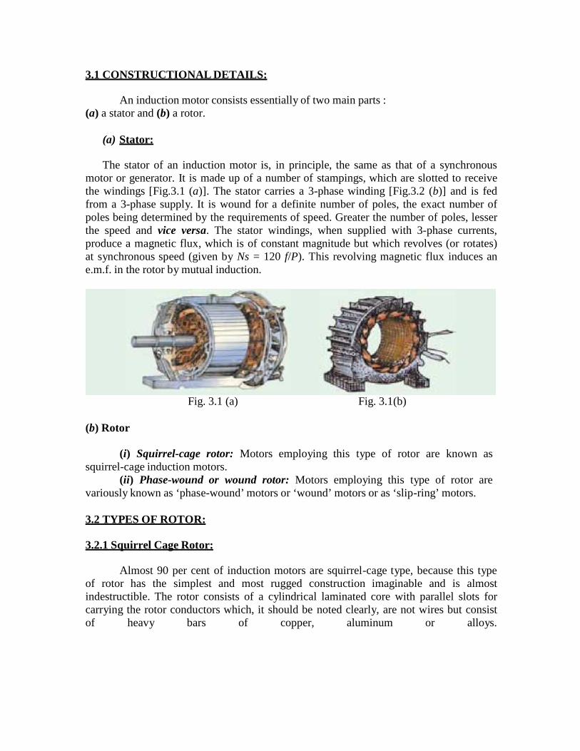
3.1 CONSTRUCTIONAL DETAILS:
An induction motor consists essentially of two main parts :(a) a stator and (b) a rotor.
(a) Stator:
The stator of an induction motor is, in principle, the same as that of a synchronousmotor or generator. It is made up of a number of stampings, which are slotted to receivethe windings [Fig.3.1 (a)]. The stator carries a 3-phase winding [Fig.3.2 (b)] and is fedfrom a 3-phase supply. It is wound for a definite number of poles, the exact number ofpoles being determined by the requirements of speed. Greater the number of poles, lesserthe speed and vice versa. The stator windings, when supplied with 3-phase currents,produce a magnetic flux, which is of constant magnitude but which revolves (or rotates)at synchronous speed (given by Ns = 120 f/P). This revolving magnetic flux induces ane.m.f. in the rotor by mutual induction.
Fig. 3.1 (a) Fig. 3.1(b)
(b) Rotor
(i) Squirrel-cage rotor: Motors employing this type of rotor are known assquirrel-cage induction motors.
(ii) Phase-wound or wound rotor: Motors employing this type of rotor arevariously known as ‘phase-wound’ motors or ‘wound’ motors or as ‘slip-ring’ motors.
3.2 TYPES OF ROTOR:
3.2.1 Squirrel Cage Rotor:
Almost 90 per cent of induction motors are squirrel-cage type, because this typeof rotor has the simplest and most rugged construction imaginable and is almostindestructible. The rotor consists of a cylindrical laminated core with parallel slots forcarrying the rotor conductors which, it should be noted clearly, are not wires but consistof heavy bars of copper, aluminum or alloys.
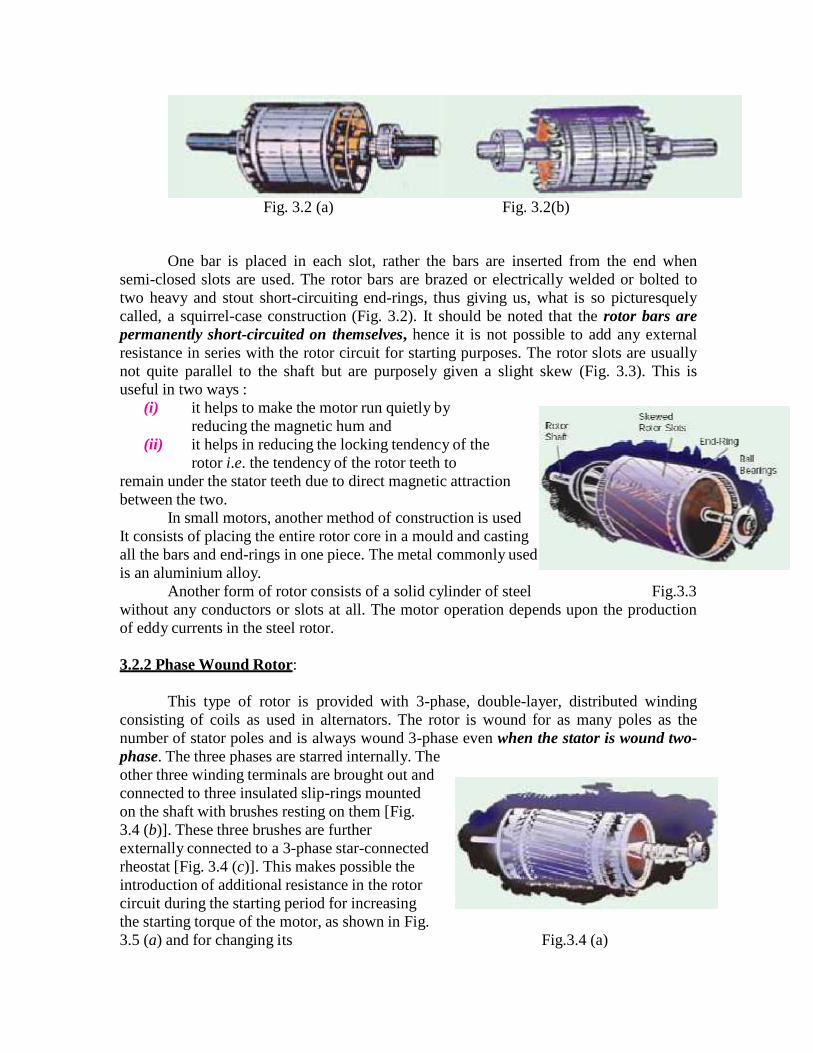
Fig. 3.2 (a) Fig. 3.2(b)
One bar is placed in each slot, rather the bars are inserted from the end whensemi-closed slots are used. The rotor bars are brazed or electrically welded or bolted totwo heavy and stout short-circuiting end-rings, thus giving us, what is so picturesquelycalled, a squirrel-case construction (Fig. 3.2). It should be noted that the rotor bars arepermanently short-circuited on themselves, hence it is not possible to add any externalresistance in series with the rotor circuit for starting purposes. The rotor slots are usuallynot quite parallel to the shaft but are purposely given a slight skew (Fig. 3.3). This isuseful in two ways :
(i) it helps to make the motor run quietly byreducing the magnetic hum and
(ii) it helps in reducing the locking tendency of therotor i.e. the tendency of the rotor teeth to
remain under the stator teeth due to direct magnetic attractionbetween the two.
In small motors, another method of construction is usedIt consists of placing the entire rotor core in a mould and castingall the bars and end-rings in one piece. The metal commonly usedis an aluminium alloy.
Another form of rotor consists of a solid cylinder of steel Fig.3.3without any conductors or slots at all. The motor operation depends upon the productionof eddy currents in the steel rotor.
3.2.2 Phase Wound Rotor:
This type of rotor is provided with 3-phase, double-layer, distributed windingconsisting of coils as used in alternators. The rotor is wound for as many poles as thenumber of stator poles and is always wound 3-phase even when the stator is wound two-phase. The three phases are starred internally. Theother three winding terminals are brought out andconnected to three insulated slip-rings mountedon the shaft with brushes resting on them [Fig.3.4 (b)]. These three brushes are furtherexternally connected to a 3-phase star-connectedrheostat [Fig. 3.4 (c)]. This makes possible theintroduction of additional resistance in the rotorcircuit during the starting period for increasingthe starting torque of the motor, as shown in Fig.3.5 (a) and for changing its Fig.3.4 (a)

speed-torque/current characteristics. When running under normal conditions, the slip-rings are automatically short-circuited by means of a metal collar, which is pushedalong the shaft and connects all the rings together. Next, the brushes are automaticallylifted from the slip-rings to reduce the frictional losses and the wear and tear. Hence, it isseen that under normal running conditions, the wound rotor is short-circuited on itself justlike the squirrel-cage rotor. Fig. 3.5 (b) shows the longitudinal section of a slip-ringmotor, whose structural details are as under:
Fig.3.4 (b) Fig.3.4 (c)
Fig.3.5 (a) Fig.3.5 (b)
1. Frame. Made of close-grained alloy cast iron.2. Stator and Rotor Core. Built from high-quality low-loss silicon steel laminations andflash-enameled on both sides.3. Stator and Rotor Windings. Have moisture proof tropical insulation embodying micaand high quality varnishes. Are carefully spaced for most effective air circulation and arerigidly braced to withstand centrifugal forces and any short-circuit stresses.4. Air-gap. The stator rabbets and bore are machined carefully to ensure uniformity ofair-gap.5. Shafts and Bearings. Ball and roller bearings are used to suit heavy duty, toruble-freerunning and for enhanced service life.6. Fans. Light aluminum fans are used for adequate circulation of cooling air and aresecurely keyed onto the rotor shaft.7. Slip-rings and Slip-ring Enclosures. Slip-rings are made of high quality phosphor-bronze and are of molded construction.

Fig. 3.5 (c) shows the disassembled view of an induction motor with squirrel-cage rotor.According to the labeled notation (a) represents stator (b) rotor (c) bearing shields (d) fan(e) ventilation grill and (f) terminal box.
Similarly, Fig. 3.5 (d) shows the disassembled view of a slip-ring motor where (a)represents stator (b) rotor (c) bearing shields (d) fan (e) ventilation grill (f) terminal box(g) slip-rings (h) brushes and brush holders.
Fig.3.5 (c) Fig.3.5 (d)
3.3 PRINCIPLE OF OPERATION:
As a general rule, conversion of electrical power intomechanical power takes place in the rotating part of anelectric motor. In d.c. motors, the electric power isconducted directly to the armature (i.e. rotating part)through brushes and commutator (Art. 29.1). Hence,in this sense, a d.c. motor can be called a conductionmotor. However, in a.c. motors, the rotor does notreceive electric power by conduction but byinduction in exactly the same way as the secondary Fig.3.6of a 2-winding transformer receives its power from the primary. That is why such motorsare known as induction motors. In fact, an induction motor can be treated as a rotatingtransformer i.e. one in which primary winding is stationary but the secondary is free torotate. Of all the a.c. motors, the polyphase induction motor is the one which isextensively used for various kinds of industrial drives. It has the following mainadvantages and also some dis-advantages:
Advantages:
1. It has very simple and extremely rugged, almost unbreakable construction(especially squirrel cage type).
2. Its cost is low and it is very reliable.3. It has sufficiently high efficiency. In normal running condition, no brushes are
needed, hence frictional losses are reduced. It has a reasonably good power factor.
4. It requires minimum of maintenance.5. It starts up from rest and needs no extra starting motor and has not to be
synchronized. Its starting arrangement is simple especially for squirrel-cage type motor.
Disadvantages:
1. Its speed cannot be varied without sacrificing some of its efficiency.2. Just like a d.c. shunt motor, its speed decreases with increase in load.3. Its starting torque is somewhat inferior to that of a D.C. shunt motor.
3.3.1 Why does the rotor rotate?
The reason why the rotor of an induction motor is set into rotation is as follow:
When the 3-phase stator windings, are fed by a 3-phase supply then, as seen fromabove, a magnetic flux of constant magnitude, but rotating at synchronous speed, is setup.
The flux passes through the air-gap, sweeps past the rotor surface and so cuts therotor conductors which, as yet, are stationary. Due to the relative speed between therotating flux and the stationary conductors, an e.m.f. is induced in the latter, according toFaraday’s laws of electro-magnetic induction. The frequency of the induced e.m.f. is thesame as the supply frequency. Its magnitude is proportional to the relative velocitybetween the flux and the conductors and its direction is given by Fleming’s Right-handrule. Since the rotor bars or conductors form a closed circuit, rotor current is producedwhose direction, as given by Lenz’s law, is such as to oppose the very cause producing it.In this case, the cause which produces the rotor current is the relative velocity betweenthe rotating flux of the stator and the stationary rotor conductors. Hence, to reduce therelative speed, the rotor starts running in the same direction as that of the flux and tries tocatch up with the rotating flux.
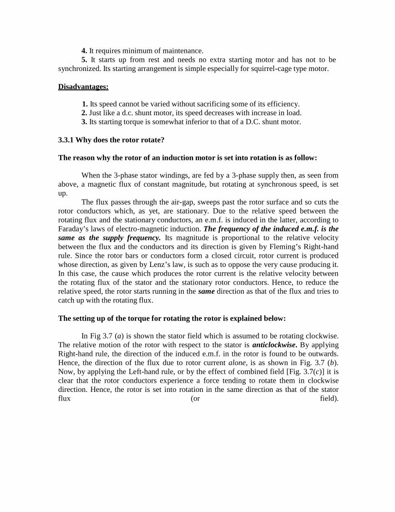
The setting up of the torque for rotating the rotor is explained below:
In Fig 3.7 (a) is shown the stator field which is assumed to be rotating clockwise.The relative motion of the rotor with respect to the stator is anticlockwise. By applyingRight-hand rule, the direction of the induced e.m.f. in the rotor is found to be outwards.Hence, the direction of the flux due to rotor current alone, is as shown in Fig. 3.7 (b).Now, by applying the Left-hand rule, or by the effect of combined field [Fig. 3.7(c)] it isclear that the rotor conductors experience a force tending to rotate them in clockwisedirection. Hence, the rotor is set into rotation in the same direction as that of the statorflux (or field).
Fig. 3.7
3.4 SLIP:
In practice, the rotor never succeeds in ‘catching up’ with the stator field. If itreally did so, then there would be no relative speed between the two, hence no rotore.m.f., no rotor current and so no torque to maintain rotation. That is why the rotor runs ata speed which is always less than the speed of the stator field. The difference in speedsdepends upon the load on the motor.
The difference between the synchronous speed Ns and the actual speed N of therotor is known as slip. Though it may be expressed in so many revolutions/second, yet itis usual to express it as a percentage of the synchronous speed. Actually, the term ‘slip’ isdescriptive of the way in which the rotor ‘slips back’ from synchronism.
Sometimes, Ns − N is called the slip speed.Obviously, rotor (or motor) speed is N = Ns (1 − s).It may be kept in mind that revolving flux is rotating synchronously, relative to the stator(i.e. stationary space) but at slip speed relative to the rotor.
3.4.1 Frequency of Rotor Current:
When the rotor is stationary, the frequency of rotor current is the same as thesupply frequency. But when the rotor starts revolving, then the frequency depends uponthe relative speed or on slip speed. Let at any slip-speed, the frequency of the rotorcurrent be f’. Then
phases of rotor winding, give rise to rotor magnetic fields. These individual rotormagnetic fields produce a combined rotating magnetic field, whose speed relative to rotoris
However, the rotor itself is running at speed N with respect to space. Hence, speed ofrotor field in space = speed of rotor magnetic field relative to rotor + speed of rotorrelative to space
It means that no matter what the value of slip, rotor currents and stator currents eachproduce a sinusoidal distributed magnetic field of constant magnitude and constant spacespeed of Ns.
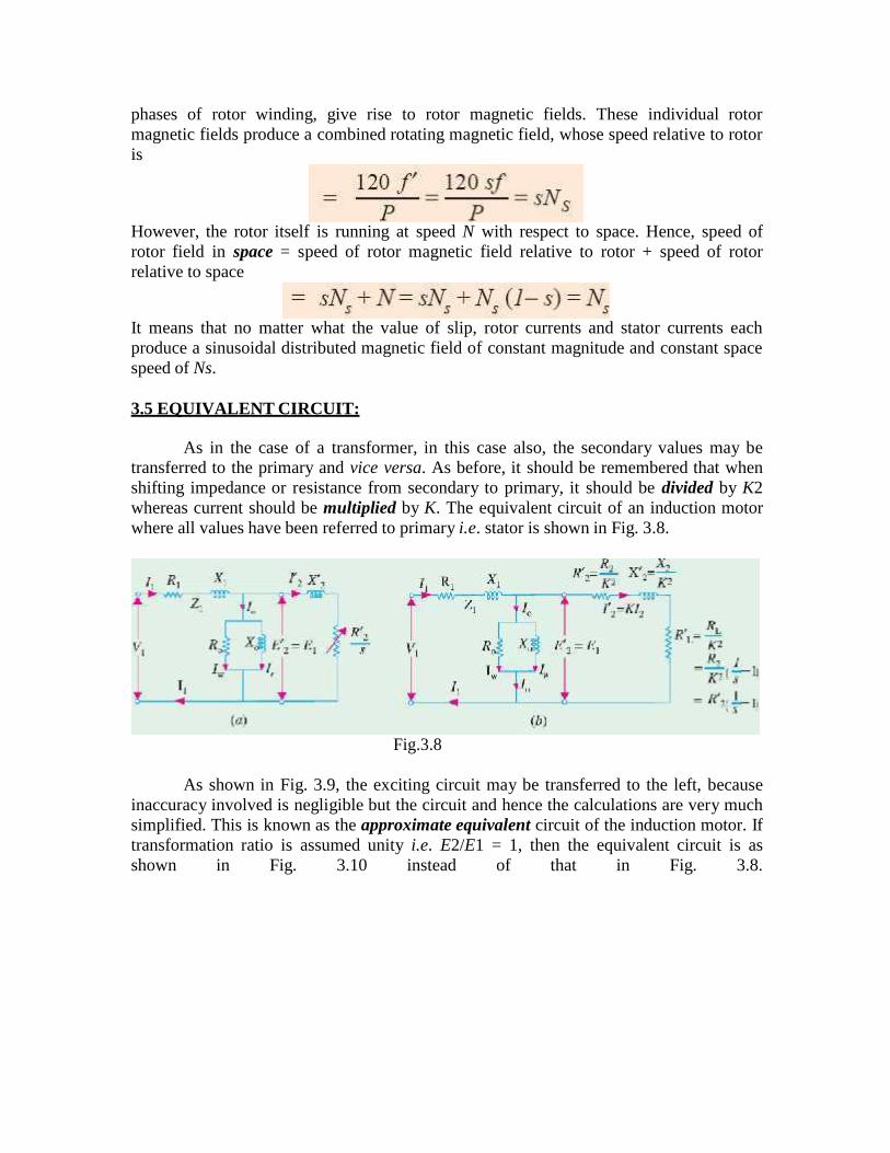
3.5 EQUIVALENT CIRCUIT:
As in the case of a transformer, in this case also, the secondary values may betransferred to the primary and vice versa. As before, it should be remembered that whenshifting impedance or resistance from secondary to primary, it should be divided by K2whereas current should be multiplied by K. The equivalent circuit of an induction motorwhere all values have been referred to primary i.e. stator is shown in Fig. 3.8.
Fig.3.8
As shown in Fig. 3.9, the exciting circuit may be transferred to the left, becauseinaccuracy involved is negligible but the circuit and hence the calculations are very muchsimplified. This is known as the approximate equivalent circuit of the induction motor. Iftransformation ratio is assumed unity i.e. E2/E1 = 1, then the equivalent circuit is asshown in Fig. 3.10 instead of that in Fig. 3.8.
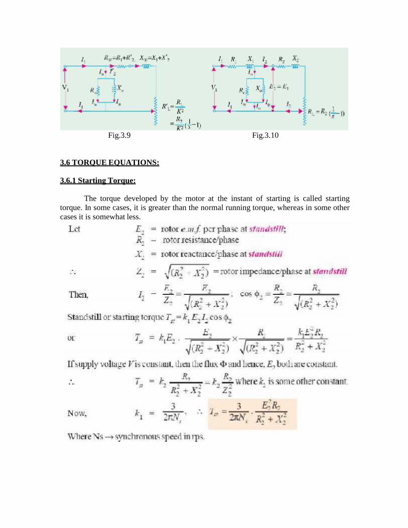
Fig.3.9 Fig.3.10
3.6 TORQUE EQUATIONS:
3.6.1 Starting Torque:
The torque developed by the motor at the instant of starting is called startingtorque. In some cases, it is greater than the normal running torque, whereas in some othercases it is somewhat less.

3.6.2 Condition for Maximum Torque:
3.6.3 Torque under Running Conditions:
3.6.4 Torque developed by Induction Motor:
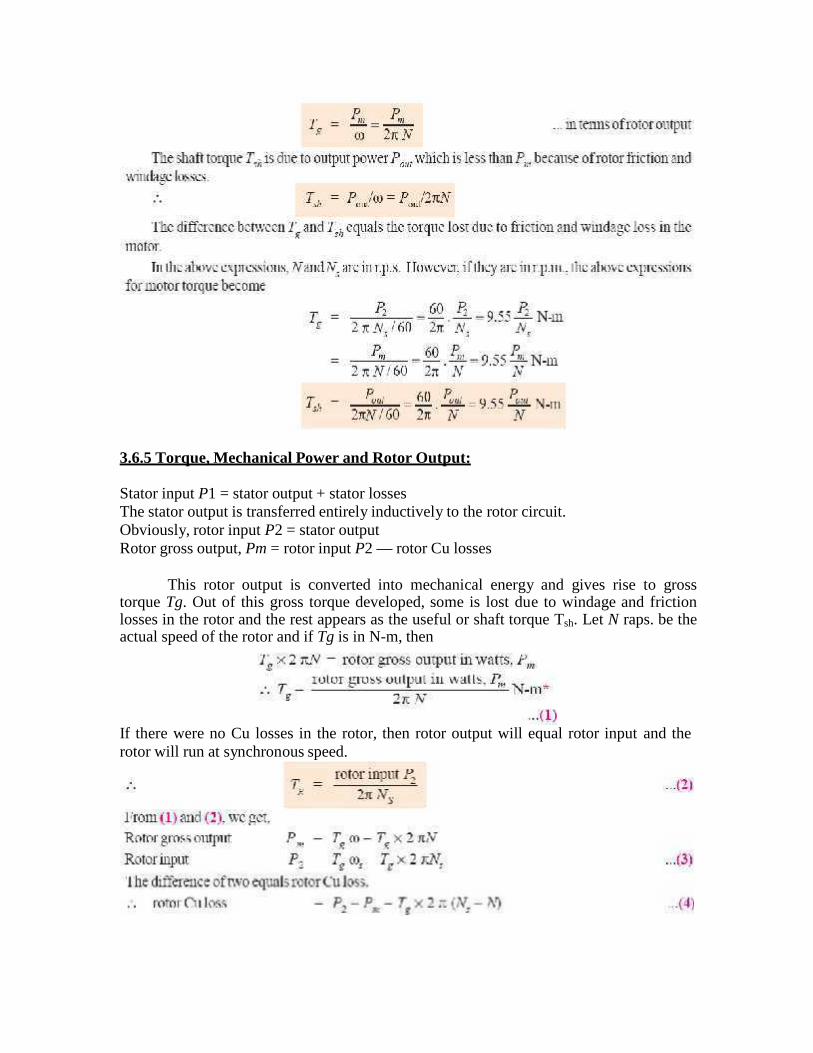
3.6.5 Torque, Mechanical Power and Rotor Output:
Stator input P1 = stator output + stator lossesThe stator output is transferred entirely inductively to the rotor circuit.Obviously, rotor input P2 = stator outputRotor gross output, Pm = rotor input P2 — rotor Cu losses
This rotor output is converted into mechanical energy and gives rise to grosstorque Tg. Out of this gross torque developed, some is lost due to windage and frictionlosses in the rotor and the rest appears as the useful or shaft torque Tsh. Let N raps. be theactual speed of the rotor and if Tg is in N-m, then
If there were no Cu losses in the rotor, then rotor output will equal rotor input and therotor will run at synchronous speed.
3.6.6 Induction Motor Torque Equation:
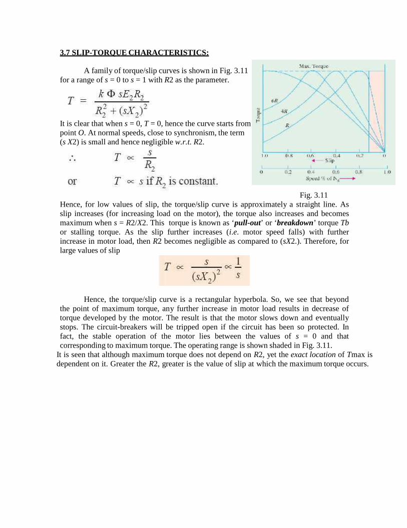
3.7 SLIP-TORQUE CHARACTERISTICS:
A family of torque/slip curves is shown in Fig. 3.11for a range of s = 0 to s = 1 with R2 as the parameter.
It is clear that when s = 0, T = 0, hence the curve starts frompoint O. At normal speeds, close to synchronism, the term(s X2) is small and hence negligible w.r.t. R2.
Fig. 3.11Hence, for low values of slip, the torque/slip curve is approximately a straight line. Asslip increases (for increasing load on the motor), the torque also increases and becomesmaximum when s = R2/X2. This torque is known as ‘pull-out’ or ‘breakdown’ torque Tbor stalling torque. As the slip further increases (i.e. motor speed falls) with furtherincrease in motor load, then R2 becomes negligible as compared to (sX2.). Therefore, forlarge values of slip
Hence, the torque/slip curve is a rectangular hyperbola. So, we see that beyondthe point of maximum torque, any further increase in motor load results in decrease oftorque developed by the motor. The result is that the motor slows down and eventuallystops. The circuit-breakers will be tripped open if the circuit has been so protected. Infact, the stable operation of the motor lies between the values of s = 0 and thatcorresponding to maximum torque. The operating range is shown shaded in Fig. 3.11.
It is seen that although maximum torque does not depend on R2, yet the exact location of Tmax isdependent on it. Greater the R2, greater is the value of slip at which the maximum torque occurs.
3.9 LOAD TEST – NO LOAD TEST AND BLOCKED ROTOR TESTS:
3.9.1 No Load Test:
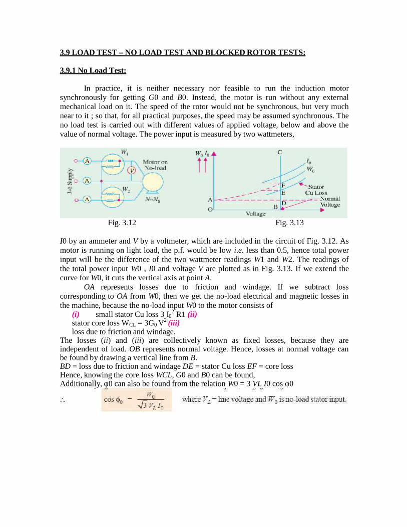
In practice, it is neither necessary nor feasible to run the induction motorsynchronously for getting G0 and B0. Instead, the motor is run without any externalmechanical load on it. The speed of the rotor would not be synchronous, but very muchnear to it ; so that, for all practical purposes, the speed may be assumed synchronous. Theno load test is carried out with different values of applied voltage, below and above thevalue of normal voltage. The power input is measured by two wattmeters,
Fig. 3.12 Fig. 3.13
I0 by an ammeter and V by a voltmeter, which are included in the circuit of Fig. 3.12. Asmotor is running on light load, the p.f. would be low i.e. less than 0.5, hence total powerinput will be the difference of the two wattmeter readings W1 and W2. The readings ofthe total power input W0 , I0 and voltage V are plotted as in Fig. 3.13. If we extend thecurve for W0, it cuts the vertical axis at point A.
OA represents losses due to friction and windage. If we subtract losscorresponding to OA from W0, then we get the no-load electrical and magnetic losses inthe machine, because the no-load input W0 to the motor consists of
(i) small stator Cu loss 3 I02 R1 (ii)
stator core loss WCL = 3G0 V2 (iii)loss due to friction and windage.
The losses (ii) and (iii) are collectively known as fixed losses, because they areindependent of load. OB represents normal voltage. Hence, losses at normal voltage canbe found by drawing a vertical line from B.BD = loss due to friction and windage DE = stator Cu loss EF = core lossHence, knowing the core loss WCL, G0 and B0 can be found,Additionally, φ0 can also be found from the relation W0 = 3 VL I0 cos φ0
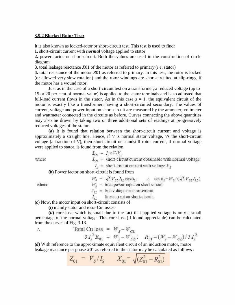
3.9.2 Blocked Rotor Test:
It is also known as locked-rotor or short-circuit test. This test is used to find:1. short-circuit current with normal voltage applied to stator2. power factor on short-circuit. Both the values are used in the construction of circlediagram3. total leakage reactance X01 of the motor as referred to primary (i.e. stator)4. total resistance of the motor R01 as referred to primary. In this test, the rotor is locked(or allowed very slow rotation) and the rotor windings are short-circuited at slip-rings, ifthe motor has a wound rotor.
Just as in the case of a short-circuit test on a transformer, a reduced voltage (up to15 or 20 per cent of normal value) is applied to the stator terminals and is so adjusted thatfull-load current flows in the stator. As in this case s = 1, the equivalent circuit of themotor is exactly like a transformer, having a short-circuited secondary. The values ofcurrent, voltage and power input on short-circuit are measured by the ammeter, voltmeterand wattmeter connected in the circuits as before. Curves connecting the above quantitiesmay also be drawn by taking two or three additional sets of readings at progressivelyreduced voltages of the stator.
(a) It is found that relation between the short-circuit current and voltage isapproximately a straight line. Hence, if V is normal stator voltage, Vs the short-circuitvoltage (a fraction of V), then short-circuit or standstill rotor current, if normal voltagewere applied to stator, is found from the relation
(b) Power factor on short-circuit is found from
(c) Now, the motor input on short-circuit consists of(i) mainly stator and rotor Cu losses(ii) core-loss, which is small due to the fact that applied voltage is only a small
percentage of the normal voltage. This core-loss (if found appreciable) can be calculatedfrom the curves of Fig. 3.13.
(d) With reference to the approximate equivalent circuit of an induction motor, motorleakage reactance per phase X01 as referred to the stator may be calculated as follows :

3.10 CIRCLE DIAGRAM:
3.10.1 Construction:
Circle diagram of an induction motor can be drawn by using the data obtained from (1)no-load (2) short-circuit test and (3) stator resistance test, as shown below.
Step No. 1From no-load test, I0 and φ0 can be calculated. Hence, as shown in Fig. 3.14,
vector for I0 can be laid off lagging φ0 behind the applied voltage V.
Fig. 3.14
Step No. 2Next, from blocked rotor test or short-circuit test, short circuit current ISN
corresponding to normal voltage and φS are found. The vector OA represents ISN =
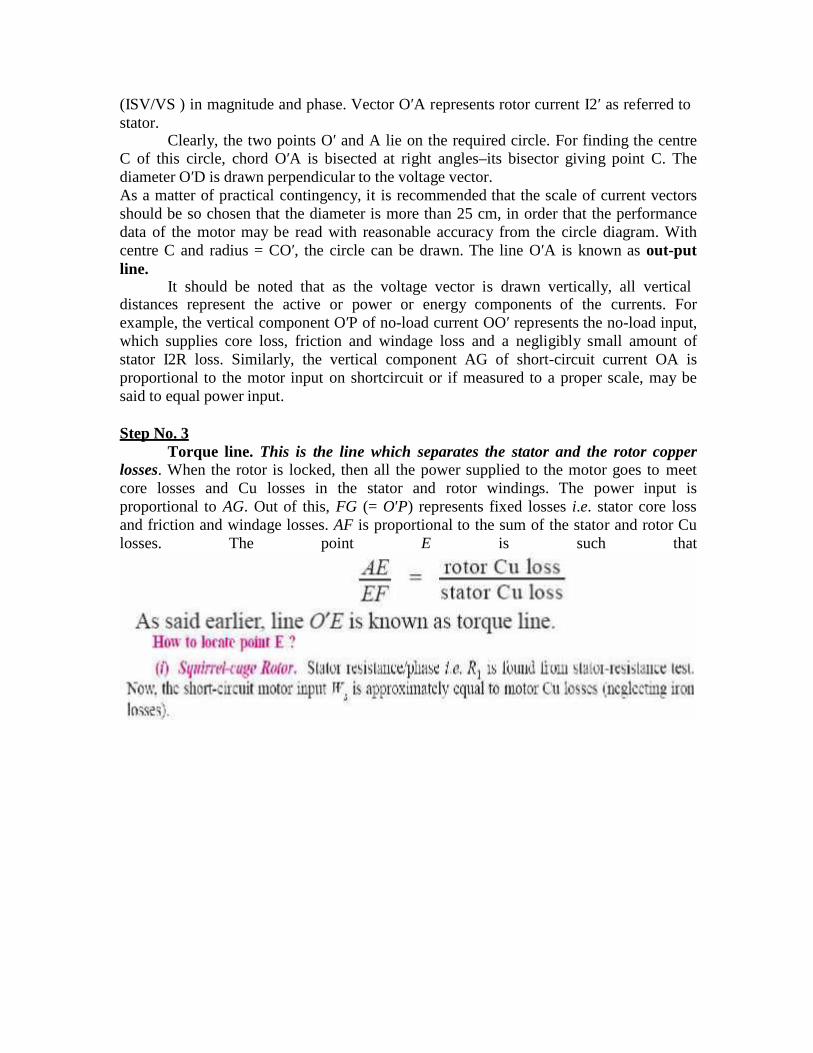
(ISV/VS ) in magnitude and phase. Vector O′A represents rotor current I2′ as referred tostator.
Clearly, the two points O′ and A lie on the required circle. For finding the centreC of this circle, chord O′A is bisected at right angles–its bisector giving point C. Thediameter O′D is drawn perpendicular to the voltage vector.As a matter of practical contingency, it is recommended that the scale of current vectorsshould be so chosen that the diameter is more than 25 cm, in order that the performancedata of the motor may be read with reasonable accuracy from the circle diagram. Withcentre C and radius = CO′, the circle can be drawn. The line O′A is known as out-putline.
It should be noted that as the voltage vector is drawn vertically, all verticaldistances represent the active or power or energy components of the currents. Forexample, the vertical component O′P of no-load current OO′ represents the no-load input,which supplies core loss, friction and windage loss and a negligibly small amount ofstator I2R loss. Similarly, the vertical component AG of short-circuit current OA isproportional to the motor input on shortcircuit or if measured to a proper scale, may besaid to equal power input.
Step No. 3Torque line. This is the line which separates the stator and the rotor copper
losses. When the rotor is locked, then all the power supplied to the motor goes to meetcore losses and Cu losses in the stator and rotor windings. The power input isproportional to AG. Out of this, FG (= O′P) represents fixed losses i.e. stator core lossand friction and windage losses. AF is proportional to the sum of the stator and rotor Culosses. The point E is such that
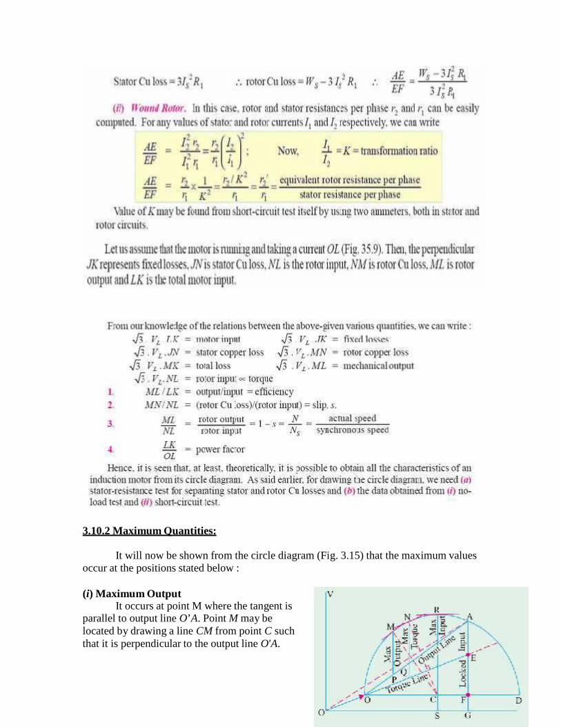
3.10.2 Maximum Quantities:
It will now be shown from the circle diagram (Fig. 3.15) that the maximum valuesoccur at the positions stated below :
(i) Maximum OutputIt occurs at point M where the tangent is
parallel to output line O’A. Point M may belocated by drawing a line CM from point C suchthat it is perpendicular to the output line O′A.

Maximum output is represented by the vertical MP.
(ii) Maximum Torque or Rotor InputIt occurs at point N where the tangent is
parallel to torque line O′E. Again, point N may befound by drawing CN perpendicular to the torqueline. Its value is represented by NQ . Maximumtorque is also known as stalling or pull-out torque.
(iii) Maximum Input PowerIt occurs at the highest point of the circle i.e. at point R where the tangent to the
circle is horizontal. It is proportional to RS. As the point R is beyond the point ofmaximum torque, the induction motor will be unstable here. However, the maximuminput is a measure of the size of the circle and is an indication of the ability of the motorto carry shorttime over-loads. Generally, RS is twice or thrice the motor input at ratedload.
3.11 SEPARATION OF NO LOAD LOSSES
The no load losses are the constant losses which include core loss and friction andwindage loss. The separation between the two can be carried out by the no load testconducted from variable voltage, rated frequency supply. When the voltage is decreasedbelow the rated value, the core loss reduces as nearly square of voltage. The slip does notincrease significantly the friction and windage loss almost remains constant.
The voltage is continuously decreased, till the machine slip suddenly begins toincrease and the motor tends to stall. At no load this takes place at a sufficiently reducedvoltage. The graph showing no load losses versus voltage is extrapolated to V =0 whichgives friction and windage loss as iron or core loss is zero at zero voltage
3.12 CRAWLING AND COGGING
3.12.1 Crawling:
It has been found that induction motors, particularly the squirrel-cage type,sometimes exhibit a tendency to run stably at speeds as low as one-seventh of theirsynchronous speed Ns. This phenomenon is known as crawling of an induction motor.
This action is due to the fact that the A.C. winding of the stator produces a fluxwave, which is not a pure sine wave. It is a complex wave consisting of a fundamentalwave, which revolves synchronously and odd harmonics like 3rd, 5th, and 7th etc. whichrotate either in the forward or backward direction at Ns / 3, Ns / 5 and Ns / 7 speedsrespectively. As a result, in addition to the fundamental torque, harmonic torques arealso developed, whose synchronous speeds are 1/nth of the speed for the fundamentaltorque i.e. Ns / n, where n is the order of the harmonic torque. Since 3rd harmoniccurrents are absent in a balanced 3-phase system, they produce no rotating field and,therefore, no torque. Hence, total motor torque has three components :
(i) the fundamental torque, rotating with the synchronous speed Ns
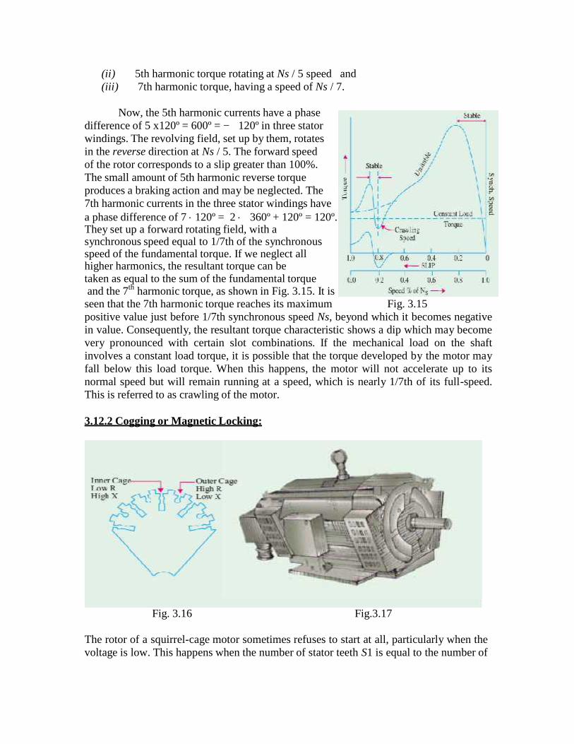
(ii) 5th harmonic torque rotating at Ns / 5 speed and(iii) 7th harmonic torque, having a speed of Ns / 7.
Now, the 5th harmonic currents have a phasedifference of 5 x120º = 600º = −120º in three statorwindings. The revolving field, set up by them, rotatesin the reverse direction at Ns / 5. The forward speedof the rotor corresponds to a slip greater than 100%.The small amount of 5th harmonic reverse torqueproduces a braking action and may be neglected. The7th harmonic currents in the three stator windings havea phase difference of 7 120º = 2 360º + 120º = 120º.They set up a forward rotating field, with asynchronous speed equal to 1/7th of the synchronousspeed of the fundamental torque. If we neglect allhigher harmonics, the resultant torque can betaken as equal to the sum of the fundamental torqueand the 7th harmonic torque, as shown in Fig. 3.15. It is
seen that the 7th harmonic torque reaches its maximum Fig. 3.15positive value just before 1/7th synchronous speed Ns, beyond which it becomes negativein value. Consequently, the resultant torque characteristic shows a dip which may becomevery pronounced with certain slot combinations. If the mechanical load on the shaftinvolves a constant load torque, it is possible that the torque developed by the motor mayfall below this load torque. When this happens, the motor will not accelerate up to itsnormal speed but will remain running at a speed, which is nearly 1/7th of its full-speed.This is referred to as crawling of the motor.
3.12.2 Cogging or Magnetic Locking:
Fig. 3.16 Fig.3.17
The rotor of a squirrel-cage motor sometimes refuses to start at all, particularly when thevoltage is low. This happens when the number of stator teeth S1 is equal to the number of

rotor teeth S2 and is due to the magnetic locking between the stator and rotor teeth. Thatis why this phenomenon is sometimes referred to as teeth-locking.
It is found that the reluctance of the magnetic path is minimum when the statorand rotor teeth face each other rather than when the teeth of one element are opposite tothe slots on the other. It is in such positions of minimum reluctance that the rotor tends toremain fixed and thus cause serious trouble during starting. Cogging of squirrel cagemotors can be easily overcome by making the number of rotor slots prime to the numberof stator slots.
3.13 DOUBLE CAGE ROTOR
The main disadvantage of a squirrel-cage motor is its poor starting torque,because of its low rotor resistance. The starting torque could be increased by having acage of high resistance, but then the motor will have poor efficiency under normalrunning conditions (because there will be more rotor Cu losses). The difficulty with acage motor is that its cage is permanently short-circuited, so no external resistance can beintroduced temporarily in its rotor circuit during starting period. Many efforts have beenmade to build a squirrel-cage motor which should have a high starting torque withoutsacrificing its electrical efficiency, under normal running conditions.The result is a motor, due to Boucheort, whichhas two independent cages on the same rotor,one inside the other. A punching for such adouble cage rotor is shown in Fig. 3.16.
The outer cage consists of bars of a high-resistance metal, whereas the inner cage haslow-resistance copper bars. Hence, outer cagehas high resistance and low ratio of reactance-to-resistance, whereas the inner cage has lowresistance but, being situated deep in therotor, has a large ratio of reactance-to-resistance.
Hence, the outer cage develops maximumtorque at starting, while the inner cage does so atabout 15% slip. As said earlier, at starting and atlarge slip values, frequency of induced e.m.f inthe rotor is high. So the reactance of the inner Fig. 3.18cage (= 2πf L) and therefore, its impedance are both high. Hence, very little currentflows in it. Most of the starting current is confined to outer cage, despite its highresistance. Hence, the motor develops a high starting torque due to high-resistance outercage. Double squirrel-cage motor is shown in Fig. 3.17. As the speed increases, thefrequency of the rotor e.m.f. decreases, so that the reactance and hence the impedance ofinner cage decreases and becomes very small, under normal running conditions. Most ofthe current then flows through it and hence it develops the greater part of the motortorque. In fact, when speed is normal, frequency of rotor e.m.f. is so small that thereactance of both cages is practically negligible. The current is carried by two cages inparallel, giving a low combined resistance.
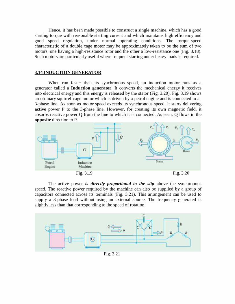
Hence, it has been made possible to construct a single machine, which has a goodstarting torque with reasonable starting current and which maintains high efficiency andgood speed regulation, under normal operating conditions. The torque-speedcharacteristic of a double cage motor may be approximately taken to be the sum of twomotors, one having a high-resistance rotor and the other a low-resistance one (Fig. 3.18).Such motors are particularly useful where frequent starting under heavy loads is required.
3.14 INDUCTION GENERATOR
When run faster than its synchronous speed, an induction motor runs as agenerator called a Induction generator. It converts the mechanical energy it receivesinto electrical energy and this energy is released by the stator (Fig. 3.20). Fig. 3.19 showsan ordinary squirrel-cage motor which is driven by a petrol engine and is connected to a3-phase line. As soon as motor speed exceeds its synchronous speed, it starts deliveringactive power P to the 3-phase line. However, for creating its own magnetic field, itabsorbs reactive power Q from the line to which it is connected. As seen, Q flows in theopposite direction to P.
Fig. 3.19 Fig. 3.20
The active power is directly proportional to the slip above the synchronousspeed. The reactive power required by the machine can also be supplied by a group ofcapacitors connected across its terminals (Fig. 3.21). This arrangement can be used tosupply a 3-phase load without using an external source. The frequency generated isslightly less than that corresponding to the speed of rotation.
Fig. 3.21

The terminal voltage increases with capacitance. If capacitance is insufficient, thegenerator voltage will not build up. Hence, capacitor bank must be large enough tosupply the reactive power normally drawn by the motor.
UNIT-IV
STARTING AND SPEED CONTROL OF THREE PHASE INDUCTION MOTOR
Need for Starting
At starting when the rotor is at standstill, the squirrel cage rotor is just like a shortcircuited secondary. Therefore the current in the rotor circuit will be high andconsequently the stator also will draw a high current from the supply lines if fullline voltage were applied at start.
A 3-phase induction motor is theoretically self starting. The stator of an
induction motor consists of 3-phase windings, which when connected to a 3-phase supply
creates a rotating magnetic field. This will link and cut the rotor conductors which in turn
will induce a current in the rotor conductors and create a rotor magnetic field. The
magnetic field created by the rotor will interact with the rotating magnetic field in the
stator and produce rotation.
Therefore, 3-phase induction motors employ a starting method not to
provide a starting torque at the rotor, but because of the following reasons;
1) Reduce heavy starting currents and prevent motor from overheating.
2) Provide overload and no-voltage protection.
Types of Starters1. Auto –Transformer Starter2. Stator resistance3. Rotor resistance4. D O L Starter5. Star Delta
Auto –Transformer Starter
A three phase auto transformer can be used to reduce the voltage applied to the stator.The advantage of this method is that the voltage is reduced by transformation and notby dropping the excess in resistor and hence the input current and power from thesupply are also reduced compared to stator resistor starting.
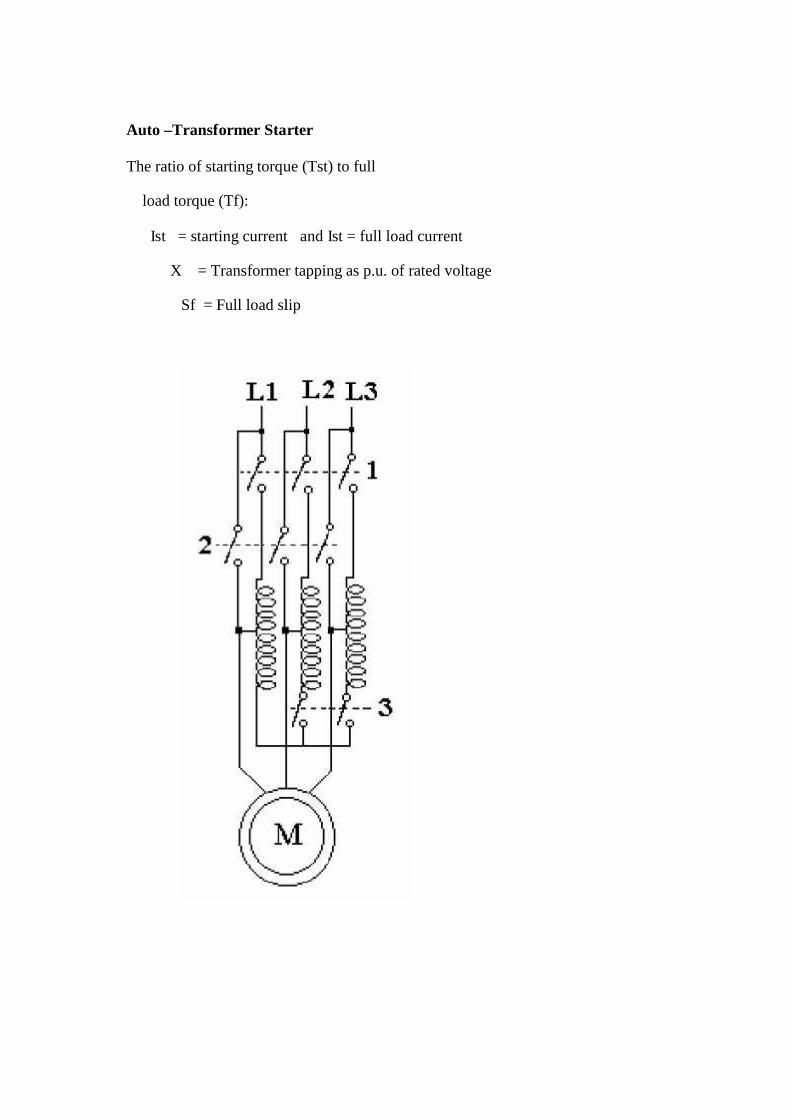
Auto –Transformer Starter
The ratio of starting torque (Tst) to full
load torque (Tf):
Ist = starting current and Ist = full load current
X = Transformer tapping as p.u. of rated voltage
Sf = Full load slip
Auto –Transformer Starter
The ratio of starting torque (Tst) to full
load torque (Tf):
Ist = starting current and Ist = full load current
X = Transformer tapping as p.u. of rated voltage
Sf = Full load slip
Auto –Transformer Starter
The ratio of starting torque (Tst) to full
load torque (Tf):
Ist = starting current and Ist = full load current
X = Transformer tapping as p.u. of rated voltage
Sf = Full load slip
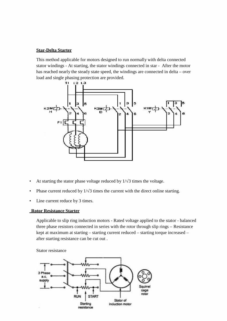
Star-Delta Starter
This method applicable for motors designed to run normally with delta connectedstator windings - At starting, the stator windings connected in star - After the motorhas reached nearly the steady state speed, the windings are connected in delta – overload and single phasing protection are provided.
• At starting the stator phase voltage reduced by 1/√3 times the voltage.
• Phase current reduced by 1/√3 times the current with the direct online starting.
• Line current reduce by 3 times.
Rotor Resistance Starter
Applicable to slip ring induction motors - Rated voltage applied to the stator - balancedthree phase resistors connected in series with the rotor through slip rings – Resistancekept at maximum at starting – starting current reduced – starting torque increased –after starting resistance can be cut out .
Stator resistance
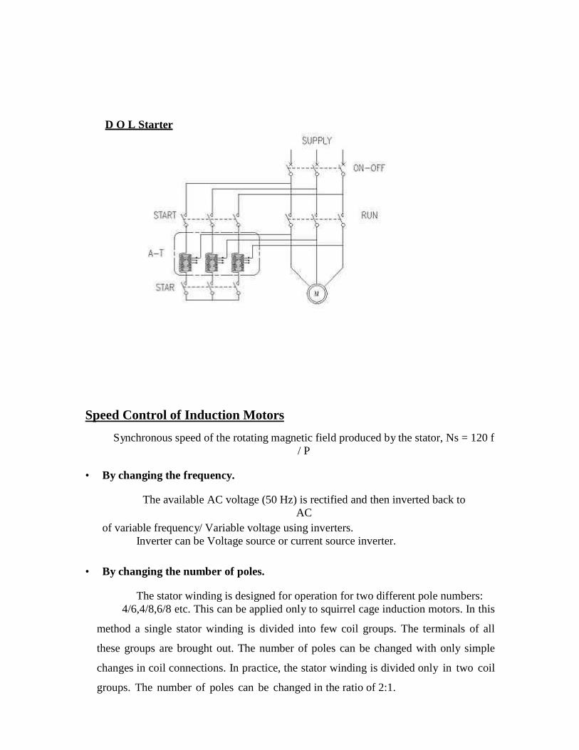
D O L Starter
Speed Control of Induction Motors
Synchronous speed of the rotating magnetic field produced by the stator, Ns = 120 f/ P
• By changing the frequency.
The available AC voltage (50 Hz) is rectified and then inverted back toAC
of variable frequency/ Variable voltage using inverters.Inverter can be Voltage source or current source inverter.
• By changing the number of poles.
The stator winding is designed for operation for two different pole numbers:4/6,4/8,6/8 etc. This can be applied only to squirrel cage induction motors. In this
method a single stator winding is divided into few coil groups. The terminals of all
these groups are brought out. The number of poles can be changed with only simple
changes in coil connections. In practice, the stator winding is divided only in two coil
groups. The number of poles can be changed in the ratio of 2:1.
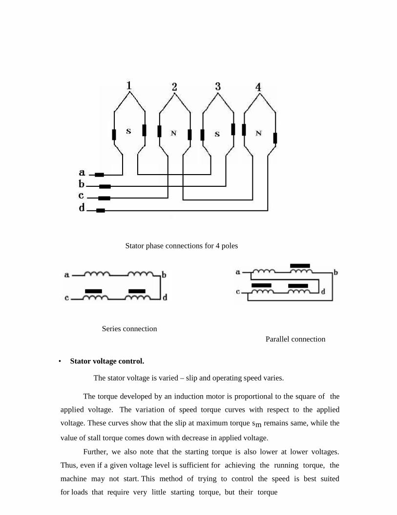
Stator phase connections for 4 poles
Series connectionParallel connection
• Stator voltage control.
The stator voltage is varied – slip and operating speed varies.
The torque developed by an induction motor is proportional to the square of the
applied voltage. The variation of speed torque curves with respect to the applied
voltage. These curves show that the slip at maximum torque sm remains same, while the
value of stall torque comes down with decrease in applied voltage.
Further, we also note that the starting torque is also lower at lower voltages.
Thus, even if a given voltage level is sufficient for achieving the running torque, the
machine may not start. This method of trying to control the speed is best suited
for loads that require very little starting torque, but their torque

Rotor resistance control
This method is applied to slip ring induction motor – rotor is connected to variable
resistance through slip rings – resistance varied – slip and hence the operating speed
varies – this method results in power loss in the resistor
Torque - speed curves for various terminal voltages
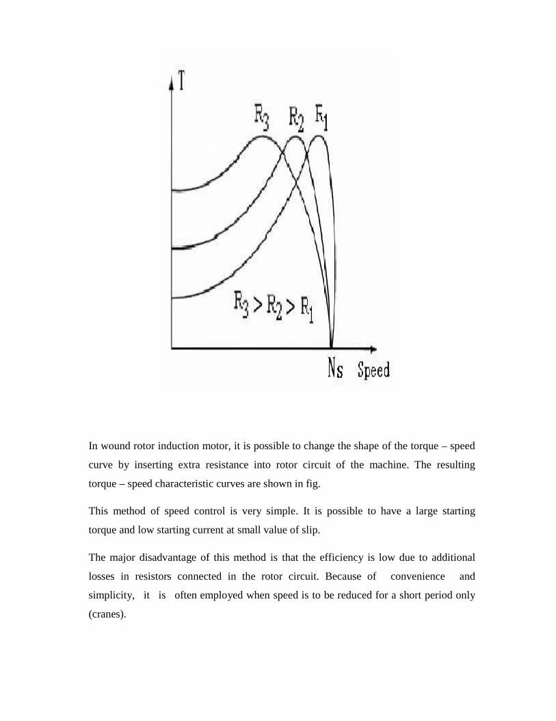
In wound rotor induction motor, it is possible to change the shape of the torque – speed
curve by inserting extra resistance into rotor circuit of the machine. The resulting
torque – speed characteristic curves are shown in fig.
This method of speed control is very simple. It is possible to have a large starting
torque and low starting current at small value of slip.
The major disadvantage of this method is that the efficiency is low due to additional
losses in resistors connected in the rotor circuit. Because of convenience and
simplicity, it is often employed when speed is to be reduced for a short period only
(cranes).
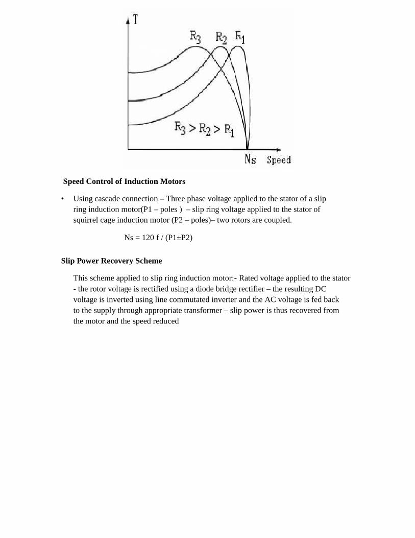
Speed Control of Induction Motors
• Using cascade connection – Three phase voltage applied to the stator of a slipring induction motor(P1 – poles ) – slip ring voltage applied to the stator ofsquirrel cage induction motor (P2 – poles)– two rotors are coupled.
Ns = 120 f / (P1±P2)
Slip Power Recovery Scheme
This scheme applied to slip ring induction motor:- Rated voltage applied to the stator- the rotor voltage is rectified using a diode bridge rectifier – the resulting DCvoltage is inverted using line commutated inverter and the AC voltage is fed backto the supply through appropriate transformer – slip power is thus recovered fromthe motor and the speed reduced
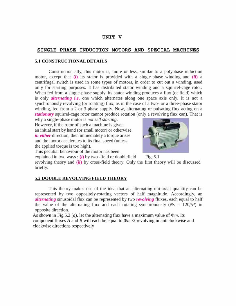
UNIT V
SINGLE PHASE INDUCTION MOTORS AND SPECIAL MACHINES
5.1 CONSTRUCTIONAL DETAILS
Construction ally, this motor is, more or less, similar to a polyphase inductionmotor, except that (i) its stator is provided with a single-phase winding and (ii) acentrifugal switch is used in some types of motors, in order to cut out a winding, usedonly for starting purposes. It has distributed stator winding and a squirrel-cage rotor.When fed from a single-phase supply, its stator winding produces a flux (or field) whichis only alternating i.e. one which alternates along one space axis only. It is not asynchronously revolving (or rotating) flux, as in the case of a two- or a three-phase statorwinding, fed from a 2-or 3-phase supply. Now, alternating or pulsating flux acting on astationary squirrel-cage rotor cannot produce rotation (only a revolving flux can). That iswhy a single-phase motor is not self starting.However, if the rotor of such a machine is givenan initial start by hand (or small motor) or otherwise,in either direction, then immediately a torque arisesand the motor accelerates to its final speed (unlessthe applied torque is too high).This peculiar behaviour of the motor has beenexplained in two ways : (i) by two -field or doublefield Fig. 5.1revolving theory and (ii) by cross-field theory. Only the first theory will be discussedbriefly.
5.2 DOUBLE REVOLVING FIELD THEORY
This theory makes use of the idea that an alternating uni-axial quantity can berepresented by two oppositely-rotating vectors of half magnitude. Accordingly, analternating sinusoidal flux can be represented by two revolving fluxes, each equal to halfthe value of the alternating flux and each rotating synchronously (Ns = 120f/P) inopposite direction.
As shown in Fig.5.2 (a), let the alternating flux have a maximum value of Φm. Itscomponent fluxes A and B will each be equal to Φm /2 revolving in anticlockwise andclockwise directions respectively
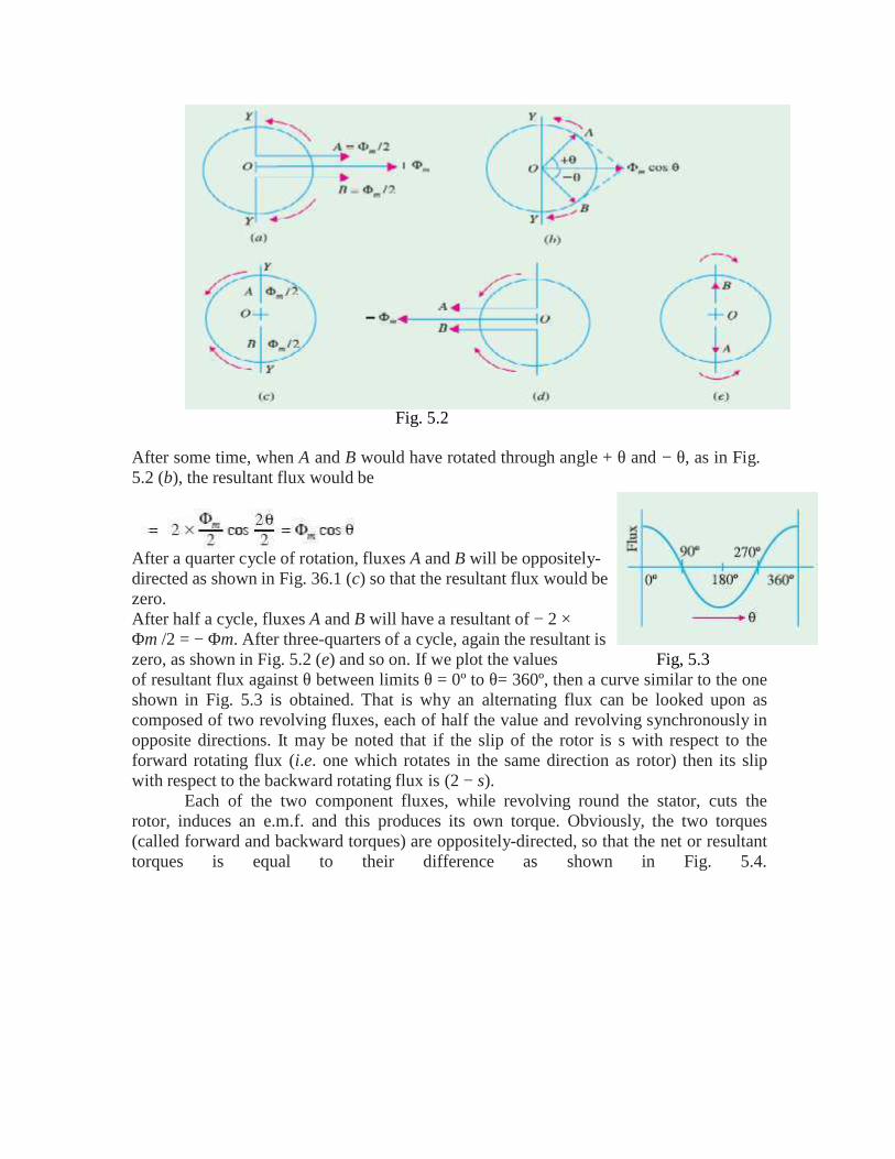
Fig. 5.2
After some time, when A and B would have rotated through angle + θ and − θ, as in Fig.5.2 (b), the resultant flux would be
After a quarter cycle of rotation, fluxes A and B will be oppositely-directed as shown in Fig. 36.1 (c) so that the resultant flux would bezero.After half a cycle, fluxes A and B will have a resultant of − 2 ×Φm /2 = − Φm. After three-quarters of a cycle, again the resultant iszero, as shown in Fig. 5.2 (e) and so on. If we plot the values Fig, 5.3of resultant flux against θ between limits θ = 0º to θ= 360º, then a curve similar to the oneshown in Fig. 5.3 is obtained. That is why an alternating flux can be looked upon ascomposed of two revolving fluxes, each of half the value and revolving synchronously inopposite directions. It may be noted that if the slip of the rotor is s with respect to theforward rotating flux (i.e. one which rotates in the same direction as rotor) then its slipwith respect to the backward rotating flux is (2 − s).
Each of the two component fluxes, while revolving round the stator, cuts therotor, induces an e.m.f. and this produces its own torque. Obviously, the two torques(called forward and backward torques) are oppositely-directed, so that the net or resultanttorques is equal to their difference as shown in Fig. 5.4.
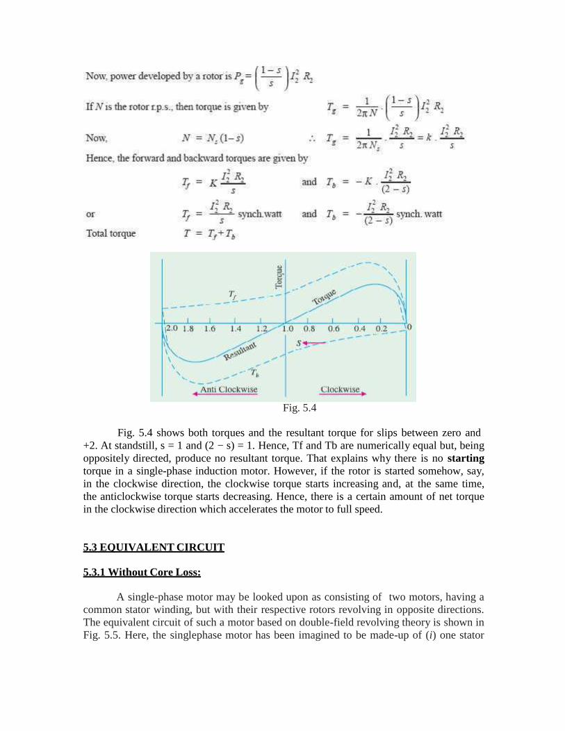
Fig. 5.4
Fig. 5.4 shows both torques and the resultant torque for slips between zero and+2. At standstill, s = 1 and (2 − s) = 1. Hence, Tf and Tb are numerically equal but, beingoppositely directed, produce no resultant torque. That explains why there is no startingtorque in a single-phase induction motor. However, if the rotor is started somehow, say,in the clockwise direction, the clockwise torque starts increasing and, at the same time,the anticlockwise torque starts decreasing. Hence, there is a certain amount of net torquein the clockwise direction which accelerates the motor to full speed.
5.3 EQUIVALENT CIRCUIT
5.3.1 Without Core Loss:
A single-phase motor may be looked upon as consisting of two motors, having acommon stator winding, but with their respective rotors revolving in opposite directions.The equivalent circuit of such a motor based on double-field revolving theory is shown inFig. 5.5. Here, the singlephase motor has been imagined to be made-up of (i) one stator
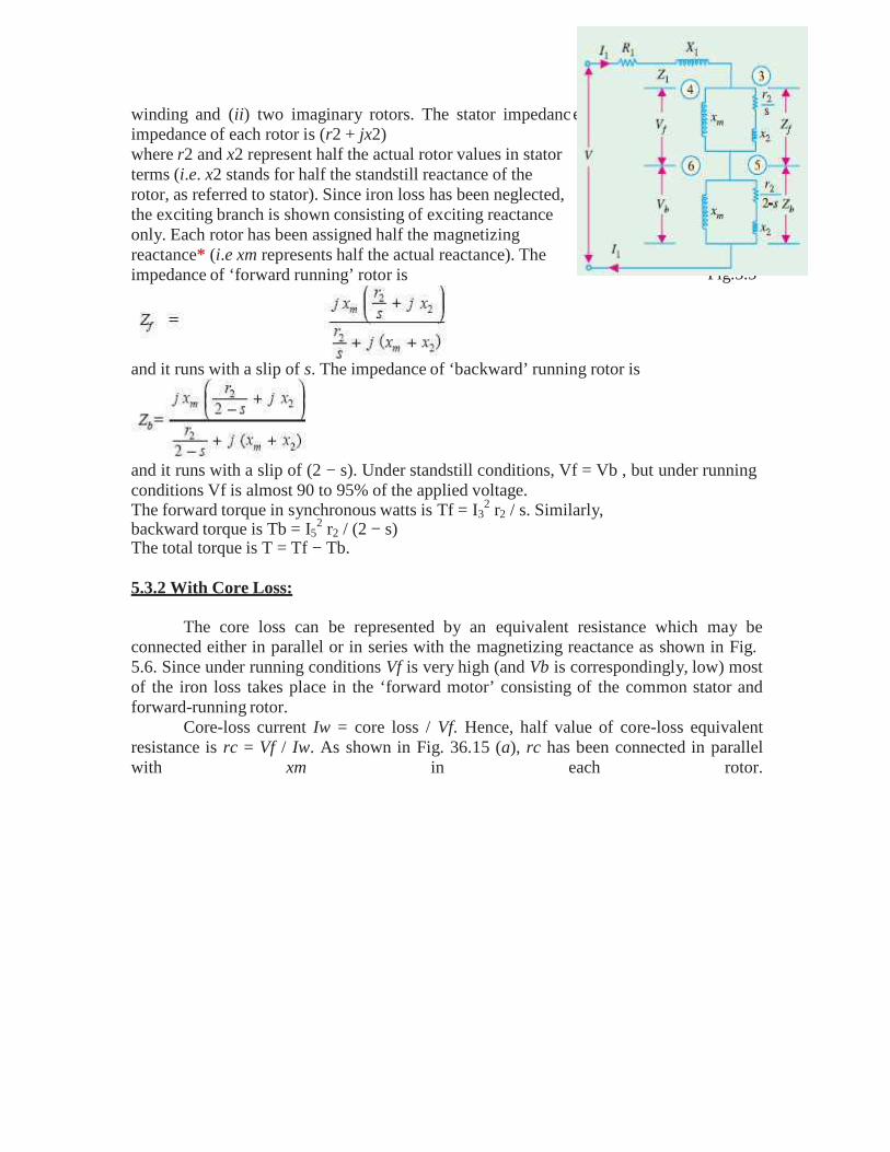
e is Z = R1 + j X1. The
Fig.5.5
winding and (ii) two imaginary rotors. The stator impedancimpedance of each rotor is (r2 + jx2)where r2 and x2 represent half the actual rotor values in statorterms (i.e. x2 stands for half the standstill reactance of therotor, as referred to stator). Since iron loss has been neglected,the exciting branch is shown consisting of exciting reactanceonly. Each rotor has been assigned half the magnetizingreactance* (i.e xm represents half the actual reactance). Theimpedance of ‘forward running’ rotor is
and it runs with a slip of s. The impedance of ‘backward’ running rotor is
and it runs with a slip of (2 − s). Under standstill conditions, Vf = Vb , but under runningconditions Vf is almost 90 to 95% of the applied voltage.The forward torque in synchronous watts is Tf = I3
2 r2 / s. Similarly,backward torque is Tb = I5
2 r2 / (2 − s)The total torque is T = Tf − Tb.
5.3.2 With Core Loss:
The core loss can be represented by an equivalent resistance which may beconnected either in parallel or in series with the magnetizing reactance as shown in Fig.5.6. Since under running conditions Vf is very high (and Vb is correspondingly, low) mostof the iron loss takes place in the ‘forward motor’ consisting of the common stator andforward-running rotor.
Core-loss current Iw = core loss / Vf. Hence, half value of core-loss equivalentresistance is rc = Vf / Iw. As shown in Fig. 36.15 (a), rc has been connected in parallelwith xm in each rotor.
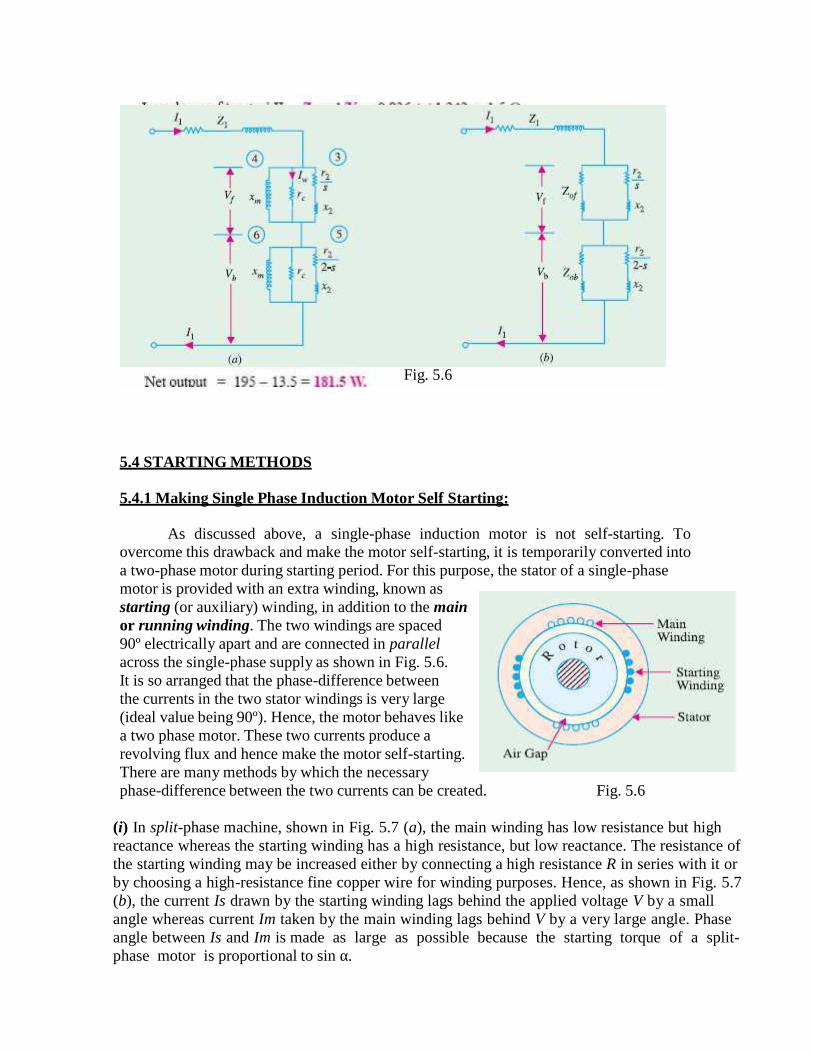
Fig. 5.6
5.4 STARTING METHODS
5.4.1 Making Single Phase Induction Motor Self Starting:
As discussed above, a single-phase induction motor is not self-starting. Toovercome this drawback and make the motor self-starting, it is temporarily converted intoa two-phase motor during starting period. For this purpose, the stator of a single-phasemotor is provided with an extra winding, known asstarting (or auxiliary) winding, in addition to the mainor running winding. The two windings are spaced90º electrically apart and are connected in parallelacross the single-phase supply as shown in Fig. 5.6.It is so arranged that the phase-difference betweenthe currents in the two stator windings is very large(ideal value being 90º). Hence, the motor behaves likea two phase motor. These two currents produce arevolving flux and hence make the motor self-starting.There are many methods by which the necessaryphase-difference between the two currents can be created. Fig. 5.6
(i) In split-phase machine, shown in Fig. 5.7 (a), the main winding has low resistance but highreactance whereas the starting winding has a high resistance, but low reactance. The resistance ofthe starting winding may be increased either by connecting a high resistance R in series with it orby choosing a high-resistance fine copper wire for winding purposes. Hence, as shown in Fig. 5.7(b), the current Is drawn by the starting winding lags behind the applied voltage V by a smallangle whereas current Im taken by the main winding lags behind V by a very large angle. Phaseangle between Is and Im is made as large as possible because the starting torque of a split-phase motor is proportional to sin α.
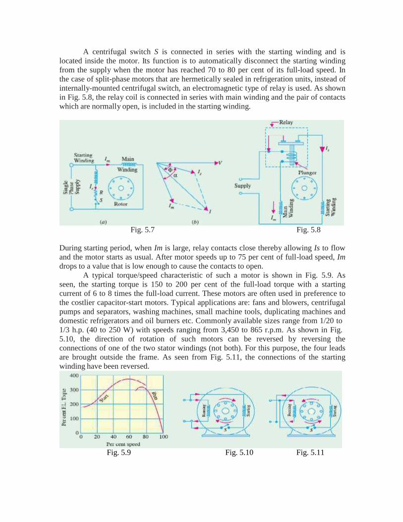
A centrifugal switch S is connected in series with the starting winding and islocated inside the motor. Its function is to automatically disconnect the starting windingfrom the supply when the motor has reached 70 to 80 per cent of its full-load speed. Inthe case of split-phase motors that are hermetically sealed in refrigeration units, instead ofinternally-mounted centrifugal switch, an electromagnetic type of relay is used. As shownin Fig. 5.8, the relay coil is connected in series with main winding and the pair of contactswhich are normally open, is included in the starting winding.
Fig. 5.7 Fig. 5.8
During starting period, when Im is large, relay contacts close thereby allowing Is to flowand the motor starts as usual. After motor speeds up to 75 per cent of full-load speed, Imdrops to a value that is low enough to cause the contacts to open.
A typical torque/speed characteristic of such a motor is shown in Fig. 5.9. Asseen, the starting torque is 150 to 200 per cent of the full-load torque with a startingcurrent of 6 to 8 times the full-load current. These motors are often used in preference tothe costlier capacitor-start motors. Typical applications are: fans and blowers, centrifugalpumps and separators, washing machines, small machine tools, duplicating machines anddomestic refrigerators and oil burners etc. Commonly available sizes range from 1/20 to1/3 h.p. (40 to 250 W) with speeds ranging from 3,450 to 865 r.p.m. As shown in Fig.5.10, the direction of rotation of such motors can be reversed by reversing theconnections of one of the two stator windings (not both). For this purpose, the four leadsare brought outside the frame. As seen from Fig. 5.11, the connections of the startingwinding have been reversed.
Fig. 5.9 Fig. 5.10 Fig. 5.11
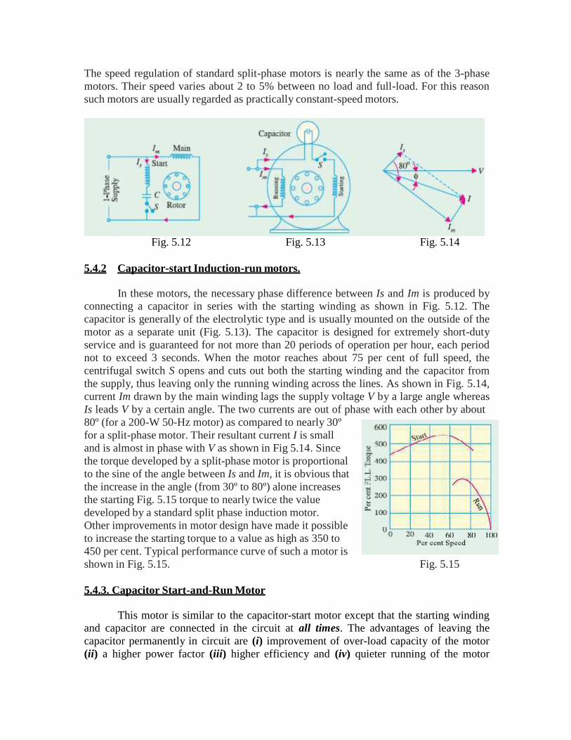
The speed regulation of standard split-phase motors is nearly the same as of the 3-phasemotors. Their speed varies about 2 to 5% between no load and full-load. For this reasonsuch motors are usually regarded as practically constant-speed motors.
Fig. 5.12 Fig. 5.13 Fig. 5.14
5.4.2 Capacitor-start Induction-run motors.
In these motors, the necessary phase difference between Is and Im is produced byconnecting a capacitor in series with the starting winding as shown in Fig. 5.12. Thecapacitor is generally of the electrolytic type and is usually mounted on the outside of themotor as a separate unit (Fig. 5.13). The capacitor is designed for extremely short-dutyservice and is guaranteed for not more than 20 periods of operation per hour, each periodnot to exceed 3 seconds. When the motor reaches about 75 per cent of full speed, thecentrifugal switch S opens and cuts out both the starting winding and the capacitor fromthe supply, thus leaving only the running winding across the lines. As shown in Fig. 5.14,current Im drawn by the main winding lags the supply voltage V by a large angle whereasIs leads V by a certain angle. The two currents are out of phase with each other by about80º (for a 200-W 50-Hz motor) as compared to nearly 30ºfor a split-phase motor. Their resultant current I is smalland is almost in phase with V as shown in Fig 5.14. Sincethe torque developed by a split-phase motor is proportionalto the sine of the angle between Is and Im, it is obvious thatthe increase in the angle (from 30º to 80º) alone increasesthe starting Fig. 5.15 torque to nearly twice the valuedeveloped by a standard split phase induction motor.Other improvements in motor design have made it possibleto increase the starting torque to a value as high as 350 to450 per cent. Typical performance curve of such a motor isshown in Fig. 5.15. Fig. 5.15
5.4.3. Capacitor Start-and-Run Motor
This motor is similar to the capacitor-start motor except that the starting windingand capacitor are connected in the circuit at all times. The advantages of leaving thecapacitor permanently in circuit are (i) improvement of over-load capacity of the motor(ii) a higher power factor (iii) higher efficiency and (iv) quieter running of the motor
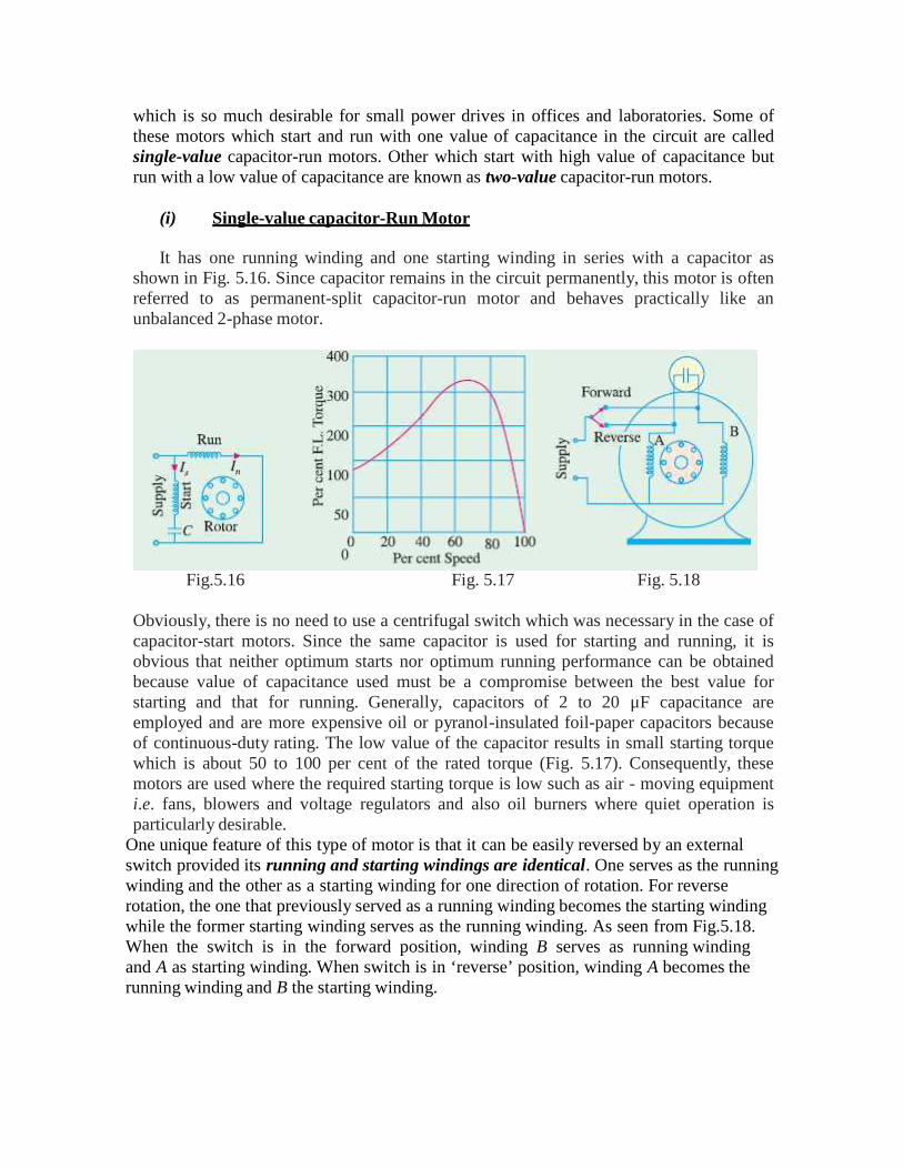
which is so much desirable for small power drives in offices and laboratories. Some ofthese motors which start and run with one value of capacitance in the circuit are calledsingle-value capacitor-run motors. Other which start with high value of capacitance butrun with a low value of capacitance are known as two-value capacitor-run motors.
(i) Single-value capacitor-Run Motor
It has one running winding and one starting winding in series with a capacitor asshown in Fig. 5.16. Since capacitor remains in the circuit permanently, this motor is oftenreferred to as permanent-split capacitor-run motor and behaves practically like anunbalanced 2-phase motor.
Fig.5.16 Fig. 5.17 Fig. 5.18
Obviously, there is no need to use a centrifugal switch which was necessary in the case ofcapacitor-start motors. Since the same capacitor is used for starting and running, it isobvious that neither optimum starts nor optimum running performance can be obtainedbecause value of capacitance used must be a compromise between the best value forstarting and that for running. Generally, capacitors of 2 to 20 μF capacitance areemployed and are more expensive oil or pyranol-insulated foil-paper capacitors becauseof continuous-duty rating. The low value of the capacitor results in small starting torquewhich is about 50 to 100 per cent of the rated torque (Fig. 5.17). Consequently, thesemotors are used where the required starting torque is low such as air - moving equipmenti.e. fans, blowers and voltage regulators and also oil burners where quiet operation isparticularly desirable.
One unique feature of this type of motor is that it can be easily reversed by an externalswitch provided its running and starting windings are identical. One serves as the runningwinding and the other as a starting winding for one direction of rotation. For reverserotation, the one that previously served as a running winding becomes the starting windingwhile the former starting winding serves as the running winding. As seen from Fig.5.18.When the switch is in the forward position, winding B serves as running windingand A as starting winding. When switch is in ‘reverse’ position, winding A becomes therunning winding and B the starting winding.
(ii) Two-value capacitor-Run Motor
This motor starts with a high capacitor in series with the starting winding so that thestarting torque is high. For running, a lower capacitor is substituted by the centrifugalswitch. Both the running and starting windings remain in circuit.The two values of capacitance can be obtained as follows:
1. by using two capacitors in parallel at the start and then switching out one forlow-value run. (Fig. 5.19) or
2. by using a step-up auto-transformer in conjunction with one capacitor so thateffective capacitance value is increased for starting purposes.In Fig. 5.19, B is an electrolytic capacitor of high capacity (short duty) and A is an oilcapacitor of low value (continuousduty). Generally, starting capacitor Bis 10 to 15 times the runningCapacitor A. At the start, when thecentrifugal switch is closed, the twocapacitors are put in parallel, so thattheir combined capacitance is thesum of their individual capacitances.After the motor has reached 75 percentfull-load speed, the switch opens andonly capacitor A remains in the startingwinding circuit. In this way, both optimum Fig. 5.19 Fig. 5.20starting and running performance is achieved in such motors. If properly designed, suchmotors have operating characteristics very closely resembling those displayed bytwo-phase motors. Their performance is characterized by
1. ability to start heavy loads2. extremely quiet operation3. higher efficiency and power factor4. ability to develop 25 per cent overload capacity
Hence, such motors are ideally suited where load requirements are severe as in thecase of compressors and fire strokers etc. The use of an auto-transformer and singleoil-type capacitor is illustrated in Fig.5.20. The transformer and capacitor are sealed in arectangular iron box and mounted on top of the motor. The idea behind using thiscombination is that a capacitor of value C connected to the secondary of a step-uptransformer, appears to the primary as though it had a value of K2C where K is voltagetransformation ratio. For example, if actual value of C = 4 F and K = 6, then low-voltage primary acts as if it had a 144 μF(=62 4) capacitor connected across itsterminals. Obviously, effective value of capacitance has increased 36 times. In the ‘start’position of the switch, the connection is made to the mid-tap of the auto-transformer sothat K = 2. Hence, effective value of capacitance at start is 4 times the running value andis sufficient to give a high starting torque. As the motor speeds up, the centrifugal switchshifts the capacitor from one voltage tap to another so that the voltage transformationratio changes from higher value at starting to a lower value for running. The capacitor
which is actually of the paper-tinfoil construction is immersed in high grade insulationlike wax or mineral oil.
5.5 TYPES AND APPLICATIONS
Such motors, which are designed to operate from asingle-phase supply, are manufactured in a large number oftypes to perform a wide variety of useful services in home,offices, factories, workshops and in business establishmentsetc. Small motors, particularly in the fractional kilo watt sizesare better known than any other. In fact, most of the newproducts of the manufacturers of space vehicles, aircrafts, Fig. 5.21business machines and power tools etc. have been possible due to the advances made inthe design of fractional-kilowatt motors. Since the performance requirements of thevarious applications differ so widely, the motor-manufacturing industry has developedmany different types of such motors, each being designed to meet specific demands.Single-phase motors may be classified as under, depending on their construction andmethod of starting :
1. Induction Motors (split-phase, capacitor and shaded-pole etc.)2. Repulsion Motors (sometime called Inductive-Series Motors)3. A.C. Series Motor4. Un-excited Synchronous Motors
5.6 WORKING PRINCIPLES OF SHADED POLE INDUCTION MOTOR,RELUCTANCE MOTOR, REPULSION MOTOR, HYSTERESIS MOTOR,STEPPER MOTOR AND UNIVERSAL MOTOR
5.6.1 Shaded Pole Induction Motor:
In such motors, the necessary phase-splitting is produced by induction. Thesemotors have salient poles on the stator and a squirrel-cage type rotor Fig. 5.22 shows afour-pole motor with the field poles connected in series for alternate polarity. One pole ofsuch a motor is shown separately in Fig. 5.23. The laminated pole has a slot cut across thelaminations approximately one-third distance from one edge. Around the small part of thepole is placed a shortcircuited Cu coil known as shading coil. This part of the pole isknown as shaded part and the other as unshaded part. When an alternating current ispassed through the exciting (or field) winding surrounding the whole pole, the axis of thepole shifts from the unshaded part a to the shaded part b. This shifting of the magneticaxis is, in effect, equivalent to the actual physical movement of the pole. Hence, the rotorstarts rotating in the direction of this shift i.e. from unshaped part to the shaded part.
Fig. 5.22 Fig. 5.23
Let us now discuss why shifting of the magnetic axis takes place. It is helpful toremember that the shading coil is highly inductive. When the alternating current throughexciting coil tends to increase, it induces a current in the shading coil by transformeraction in such a direction as to oppose its growth. Hence, flux density decreases in theshaded part when exciting current increases. However, flux density increases in theshaded part when exciting current starts decreasing (it being assumed that excitingcurrent is sinusoidal). In Fig. 5.24 (a) exciting current is rapidly increasing along OA(shown by dots). This will produce an e.m.f. in the shading coil. As shading coil is of lowresistance, a large current will be set up in such a direction (according to Lenz’s law) asto oppose the rise of exciting current (which is responsible for its production). Hence, theflux mostly shifts to the unshaded part and the magnetic axis lies along the middle of thispart i.e. along NC. Next, consider the moment when exciting current is near its peakvalue i.e. from point A to B [Fig. 5.24 (b)]. Here, the change in exciting current is veryslow. Hence, practically no voltage and, therefore, no current is induced in the shadingcoil. The flux produced by exciting current is at its maximum value and is uniformlydistributed over the pole face. So the magnetic axis shifts to the centre of the pole i.e.along positions ND.
Fig. 5.24 (c) represents the condition when the exciting current is rapidlydecreasing from B to C. This again sets up induced current in the shading coil bytransformer action. This current will flow in such a direction as to oppose this decrease inexciting current, with the result that the flux is strengthened in the shaded part of the pole.Consequently, the magnetic axis shifts to the middle part of the shaded pole i.e. alongNE.
Fig, 5.24
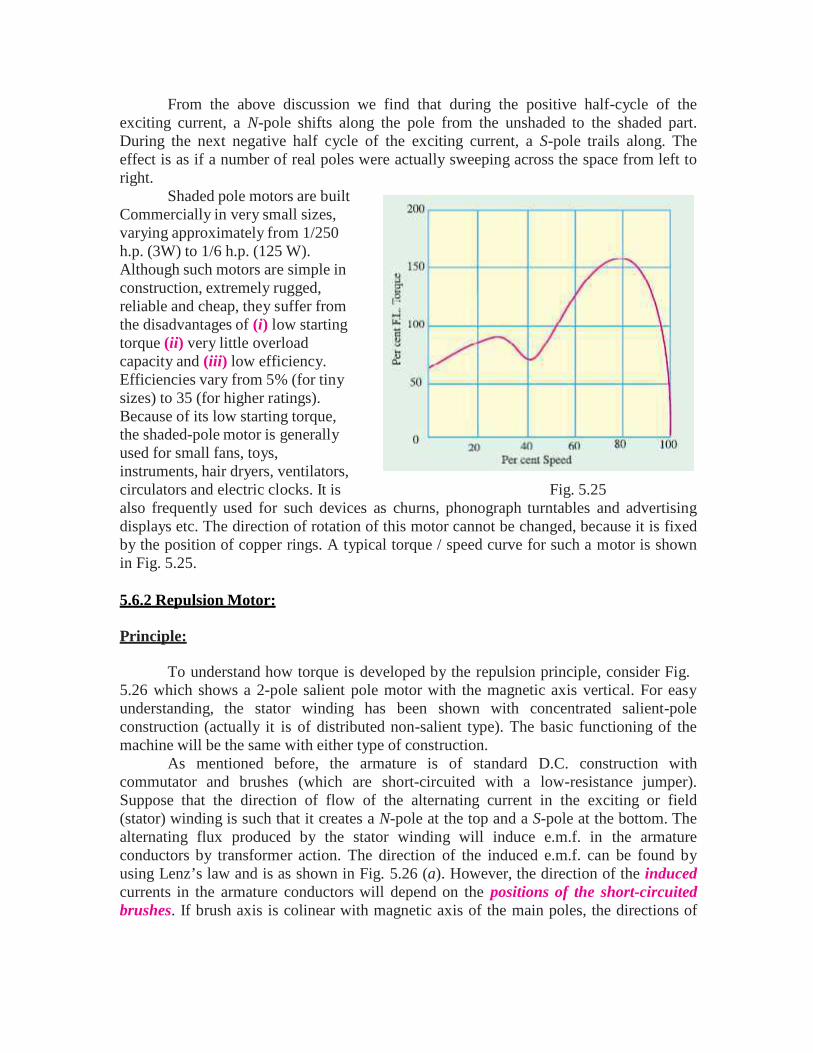
From the above discussion we find that during the positive half-cycle of theexciting current, a N-pole shifts along the pole from the unshaded to the shaded part.During the next negative half cycle of the exciting current, a S-pole trails along. Theeffect is as if a number of real poles were actually sweeping across the space from left toright.
Shaded pole motors are builtCommercially in very small sizes,varying approximately from 1/250h.p. (3W) to 1/6 h.p. (125 W).Although such motors are simple inconstruction, extremely rugged,reliable and cheap, they suffer fromthe disadvantages of (i) low startingtorque (ii) very little overloadcapacity and (iii) low efficiency.Efficiencies vary from 5% (for tinysizes) to 35 (for higher ratings).Because of its low starting torque,the shaded-pole motor is generallyused for small fans, toys,instruments, hair dryers, ventilators,circulators and electric clocks. It is Fig. 5.25also frequently used for such devices as churns, phonograph turntables and advertisingdisplays etc. The direction of rotation of this motor cannot be changed, because it is fixedby the position of copper rings. A typical torque / speed curve for such a motor is shownin Fig. 5.25.
5.6.2 Repulsion Motor:
Principle:
To understand how torque is developed by the repulsion principle, consider Fig.5.26 which shows a 2-pole salient pole motor with the magnetic axis vertical. For easyunderstanding, the stator winding has been shown with concentrated salient-poleconstruction (actually it is of distributed non-salient type). The basic functioning of themachine will be the same with either type of construction.
As mentioned before, the armature is of standard D.C. construction withcommutator and brushes (which are short-circuited with a low-resistance jumper).Suppose that the direction of flow of the alternating current in the exciting or field(stator) winding is such that it creates a N-pole at the top and a S-pole at the bottom. Thealternating flux produced by the stator winding will induce e.m.f. in the armatureconductors by transformer action. The direction of the induced e.m.f. can be found byusing Lenz’s law and is as shown in Fig. 5.26 (a). However, the direction of the inducedcurrents in the armature conductors will depend on the positions of the short-circuitedbrushes. If brush axis is colinear with magnetic axis of the main poles, the directions of
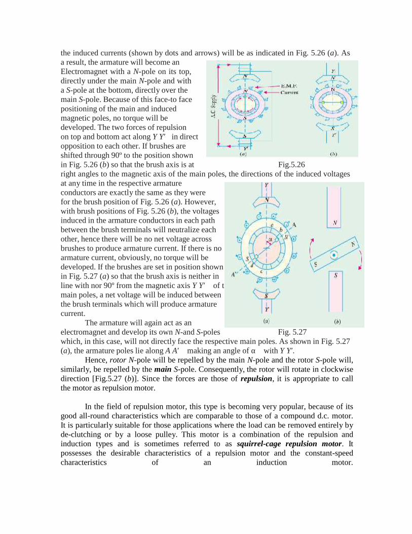
he
the induced currents (shown by dots and arrows) will be as indicated in Fig. 5.26 (a). Asa result, the armature will become anElectromagnet with a N-pole on its top,directly under the main N-pole and witha S-pole at the bottom, directly over themain S-pole. Because of this face-to facepositioning of the main and inducedmagnetic poles, no torque will bedeveloped. The two forces of repulsionon top and bottom act along Y Y′in directopposition to each other. If brushes areshifted through 90º to the position shownin Fig. 5.26 (b) so that the brush axis is at Fig.5.26right angles to the magnetic axis of the main poles, the directions of the induced voltagesat any time in the respective armatureconductors are exactly the same as they werefor the brush position of Fig. 5.26 (a). However,with brush positions of Fig. 5.26 (b), the voltagesinduced in the armature conductors in each pathbetween the brush terminals will neutralize eachother, hence there will be no net voltage acrossbrushes to produce armature current. If there is noarmature current, obviously, no torque will bedeveloped. If the brushes are set in position shownin Fig. 5.27 (a) so that the brush axis is neither inline with nor 90º from the magnetic axis Y Y′of tmain poles, a net voltage will be induced betweenthe brush terminals which will produce armaturecurrent.
The armature will again act as anelectromagnet and develop its own N-and S-poles Fig. 5.27which, in this case, will not directly face the respective main poles. As shown in Fig. 5.27(a), the armature poles lie along A A′making an angle of αwith Y Y′.
Hence, rotor N-pole will be repelled by the main N-pole and the rotor S-pole will,similarly, be repelled by the main S-pole. Consequently, the rotor will rotate in clockwisedirection [Fig.5.27 (b)]. Since the forces are those of repulsion, it is appropriate to callthe motor as repulsion motor.
In the field of repulsion motor, this type is becoming very popular, because of itsgood all-round characteristics which are comparable to those of a compound d.c. motor.It is particularly suitable for those applications where the load can be removed entirely byde-clutching or by a loose pulley. This motor is a combination of the repulsion andinduction types and is sometimes referred to as squirrel-cage repulsion motor. Itpossesses the desirable characteristics of a repulsion motor and the constant-speedcharacteristics of an induction motor.
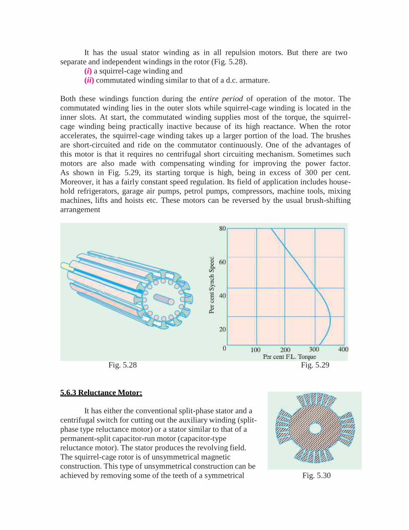
It has the usual stator winding as in all repulsion motors. But there are twoseparate and independent windings in the rotor (Fig. 5.28).
(i) a squirrel-cage winding and(ii) commutated winding similar to that of a d.c. armature.
Both these windings function during the entire period of operation of the motor. Thecommutated winding lies in the outer slots while squirrel-cage winding is located in theinner slots. At start, the commutated winding supplies most of the torque, the squirrel-cage winding being practically inactive because of its high reactance. When the rotoraccelerates, the squirrel-cage winding takes up a larger portion of the load. The brushesare short-circuited and ride on the commutator continuously. One of the advantages ofthis motor is that it requires no centrifugal short circuiting mechanism. Sometimes suchmotors are also made with compensating winding for improving the power factor.As shown in Fig. 5.29, its starting torque is high, being in excess of 300 per cent.Moreover, it has a fairly constant speed regulation. Its field of application includes house-hold refrigerators, garage air pumps, petrol pumps, compressors, machine tools, mixingmachines, lifts and hoists etc. These motors can be reversed by the usual brush-shiftingarrangement
Fig. 5.28 Fig. 5.29
5.6.3 Reluctance Motor:
It has either the conventional split-phase stator and acentrifugal switch for cutting out the auxiliary winding (split-phase type reluctance motor) or a stator similar to that of apermanent-split capacitor-run motor (capacitor-typereluctance motor). The stator produces the revolving field.The squirrel-cage rotor is of unsymmetrical magneticconstruction. This type of unsymmetrical construction can beachieved by removing some of the teeth of a symmetrical Fig. 5.30
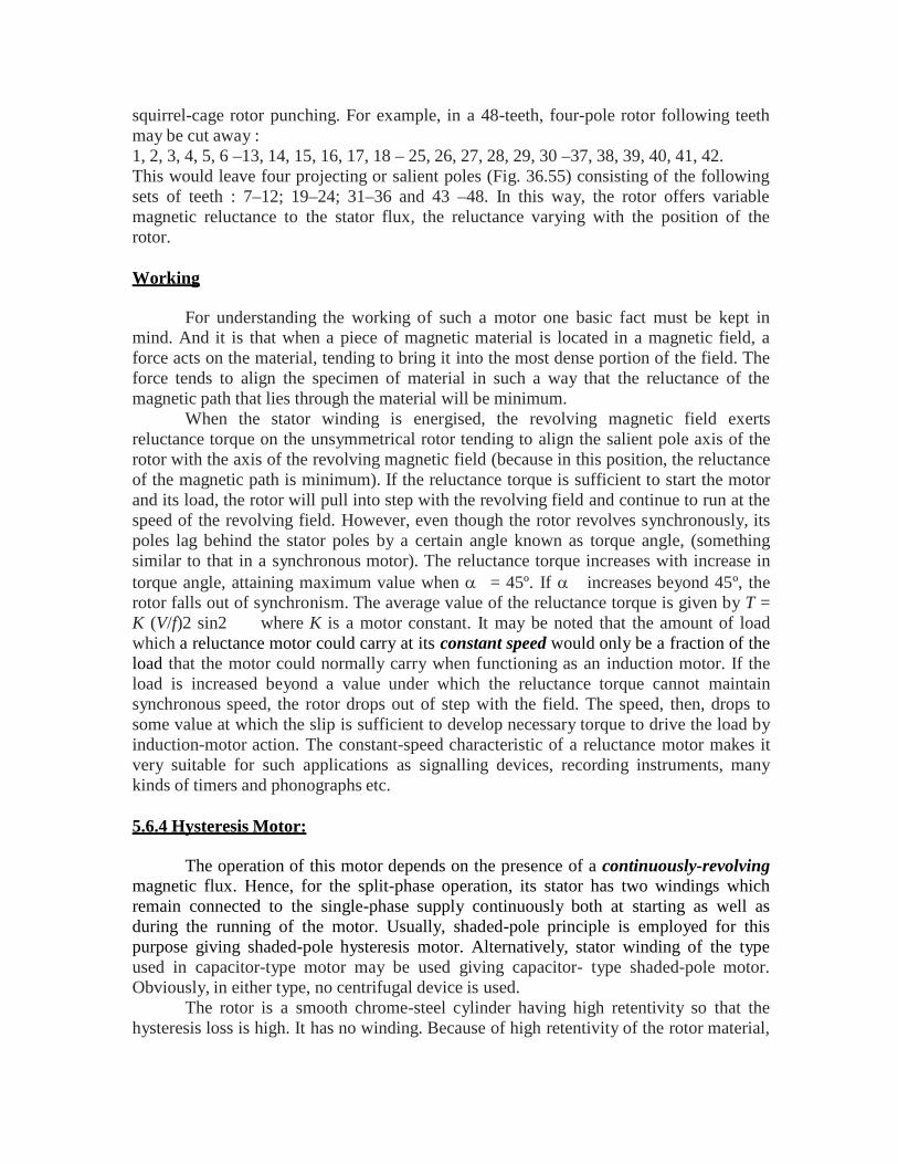
squirrel-cage rotor punching. For example, in a 48-teeth, four-pole rotor following teethmay be cut away :1, 2, 3, 4, 5, 6 –13, 14, 15, 16, 17, 18 – 25, 26, 27, 28, 29, 30 –37, 38, 39, 40, 41, 42.This would leave four projecting or salient poles (Fig. 36.55) consisting of the followingsets of teeth : 7–12; 19–24; 31–36 and 43 –48. In this way, the rotor offers variablemagnetic reluctance to the stator flux, the reluctance varying with the position of therotor.
Working
For understanding the working of such a motor one basic fact must be kept inmind. And it is that when a piece of magnetic material is located in a magnetic field, aforce acts on the material, tending to bring it into the most dense portion of the field. Theforce tends to align the specimen of material in such a way that the reluctance of themagnetic path that lies through the material will be minimum.
When the stator winding is energised, the revolving magnetic field exertsreluctance torque on the unsymmetrical rotor tending to align the salient pole axis of therotor with the axis of the revolving magnetic field (because in this position, the reluctanceof the magnetic path is minimum). If the reluctance torque is sufficient to start the motorand its load, the rotor will pull into step with the revolving field and continue to run at thespeed of the revolving field. However, even though the rotor revolves synchronously, itspoles lag behind the stator poles by a certain angle known as torque angle, (somethingsimilar to that in a synchronous motor). The reluctance torque increases with increase intorque angle, attaining maximum value when = 45º. If increases beyond 45º, therotor falls out of synchronism. The average value of the reluctance torque is given by T =K (V/f)2 sin2 where K is a motor constant. It may be noted that the amount of loadwhich a reluctance motor could carry at its constant speed would only be a fraction of theload that the motor could normally carry when functioning as an induction motor. If theload is increased beyond a value under which the reluctance torque cannot maintainsynchronous speed, the rotor drops out of step with the field. The speed, then, drops tosome value at which the slip is sufficient to develop necessary torque to drive the load byinduction-motor action. The constant-speed characteristic of a reluctance motor makes itvery suitable for such applications as signalling devices, recording instruments, manykinds of timers and phonographs etc.
5.6.4 Hysteresis Motor:
The operation of this motor depends on the presence of a continuously-revolvingmagnetic flux. Hence, for the split-phase operation, its stator has two windings whichremain connected to the single-phase supply continuously both at starting as well asduring the running of the motor. Usually, shaded-pole principle is employed for thispurpose giving shaded-pole hysteresis motor. Alternatively, stator winding of the typeused in capacitor-type motor may be used giving capacitor- type shaded-pole motor.Obviously, in either type, no centrifugal device is used.
The rotor is a smooth chrome-steel cylinder having high retentivity so that thehysteresis loss is high. It has no winding. Because of high retentivity of the rotor material,
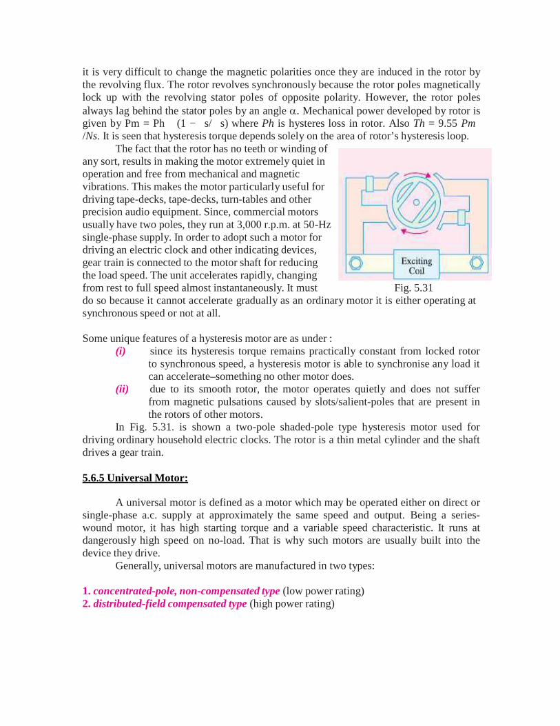
it is very difficult to change the magnetic polarities once they are induced in the rotor bythe revolving flux. The rotor revolves synchronously because the rotor poles magneticallylock up with the revolving stator poles of opposite polarity. However, the rotor polesalways lag behind the stator poles by an angle . Mechanical power developed by rotor isgiven by Pm = Ph (1 −s/s) where Ph is hysteres loss in rotor. Also Th = 9.55 Pm/Ns. It is seen that hysteresis torque depends solely on the area of rotor’s hysteresis loop.
The fact that the rotor has no teeth or winding ofany sort, results in making the motor extremely quiet inoperation and free from mechanical and magneticvibrations. This makes the motor particularly useful fordriving tape-decks, tape-decks, turn-tables and otherprecision audio equipment. Since, commercial motorsusually have two poles, they run at 3,000 r.p.m. at 50-Hzsingle-phase supply. In order to adopt such a motor fordriving an electric clock and other indicating devices,gear train is connected to the motor shaft for reducingthe load speed. The unit accelerates rapidly, changingfrom rest to full speed almost instantaneously. It must Fig. 5.31do so because it cannot accelerate gradually as an ordinary motor it is either operating atsynchronous speed or not at all.
Some unique features of a hysteresis motor are as under :(i) since its hysteresis torque remains practically constant from locked rotor
to synchronous speed, a hysteresis motor is able to synchronise any load itcan accelerate–something no other motor does.
(ii) due to its smooth rotor, the motor operates quietly and does not sufferfrom magnetic pulsations caused by slots/salient-poles that are present inthe rotors of other motors.
In Fig. 5.31. is shown a two-pole shaded-pole type hysteresis motor used fordriving ordinary household electric clocks. The rotor is a thin metal cylinder and the shaftdrives a gear train.
5.6.5 Universal Motor:
A universal motor is defined as a motor which may be operated either on direct orsingle-phase a.c. supply at approximately the same speed and output. Being a series-wound motor, it has high starting torque and a variable speed characteristic. It runs atdangerously high speed on no-load. That is why such motors are usually built into thedevice they drive.
Generally, universal motors are manufactured in two types:
1. concentrated-pole, non-compensated type (low power rating)2. distributed-field compensated type (high power rating)
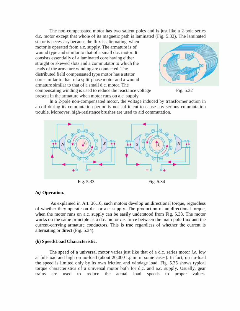
The non-compensated motor has two salient poles and is just like a 2-pole seriesd.c. motor except that whole of its magnetic path is laminated (Fig. 5.32). The laminatedstator is necessary because the flux is alternating whenmotor is operated from a.c. supply. The armature is ofwound type and similar to that of a small d.c. motor. Itconsists essentially of a laminated core having eitherstraight or skewed slots and a commutator to which theleads of the armature winding are connected. Thedistributed field compensated type motor has a statorcore similar to that of a split-phase motor and a woundarmature similar to that of a small d.c. motor. Thecompensating winding is used to reduce the reactance voltage Fig. 5.32present in the armature when motor runs on a.c. supply.
In a 2-pole non-compensated motor, the voltage induced by transformer action ina coil during its commutation period is not sufficient to cause any serious commutationtrouble. Moreover, high-resistance brushes are used to aid commutation.
Fig. 5.33 Fig. 5.34
(a) Operation.
As explained in Art. 36.16, such motors develop unidirectional torque, regardlessof whether they operate on d.c. or a.c. supply. The production of unidirectional torque,when the motor runs on a.c. supply can be easily understood from Fig. 5.33. The motorworks on the same principle as a d.c. motor i.e. force between the main pole flux and thecurrent-carrying armature conductors. This is true regardless of whether the current isalternating or direct (Fig. 5.34).
(b) Speed/Load Characteristic.
The speed of a universal motor varies just like that of a d.c. series motor i.e. lowat full-load and high on no-load (about 20,000 r.p.m. in some cases). In fact, on no-loadthe speed is limited only by its own friction and windage load. Fig. 5.35 shows typicaltorque characteristics of a universal motor both for d.c. and a.c. supply. Usually, geartrains are used to reduce the actual load speeds to proper values.
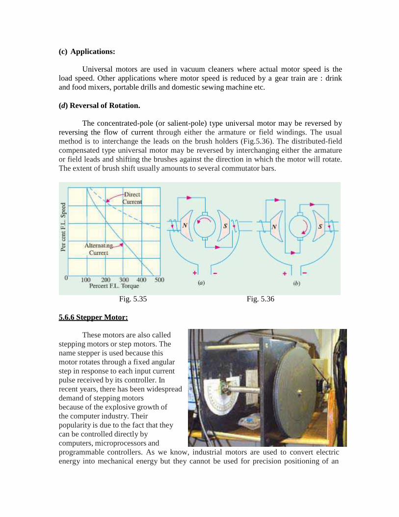
(c) Applications:
Universal motors are used in vacuum cleaners where actual motor speed is theload speed. Other applications where motor speed is reduced by a gear train are : drinkand food mixers, portable drills and domestic sewing machine etc.
(d) Reversal of Rotation.
The concentrated-pole (or salient-pole) type universal motor may be reversed byreversing the flow of current through either the armature or field windings. The usualmethod is to interchange the leads on the brush holders (Fig.5.36). The distributed-fieldcompensated type universal motor may be reversed by interchanging either the armatureor field leads and shifting the brushes against the direction in which the motor will rotate.The extent of brush shift usually amounts to several commutator bars.
Fig. 5.35 Fig. 5.36
5.6.6 Stepper Motor:
These motors are also calledstepping motors or step motors. Thename stepper is used because thismotor rotates through a fixed angularstep in response to each input currentpulse received by its controller. Inrecent years, there has been widespreaddemand of stepping motorsbecause of the explosive growth ofthe computer industry. Theirpopularity is due to the fact that theycan be controlled directly bycomputers, microprocessors andprogrammable controllers. As we know, industrial motors are used to convert electricenergy into mechanical energy but they cannot be used for precision positioning of an
object or precision control of speed without using closed-loop feedback. Stepping motorsare ideally suited for situations where either precise positioning or precise speed controlor both are required in automation systems.
Apart from stepping motors, other devices used for the above purposes aresynchros and resolvers as well as dc/ac servomotors (discussed later).
The unique feature of a stepper motor is that its output shaft rotates in a series ofdiscrete angular intervals or steps, one step being taken each time a command pulse isreceived. When a definite number of pulses are supplied, the shaft turns through adefinite known angle. This fact makes the motor well-suited for open-loop positioncontrol because no feedback need be taken from the output shaft.
Such motors develop torques ranging from 1N-m (in a tiny wrist watch motor of 3mm diameter) upto 40 N-m in a motor of 15 cm diameter suitable for machine toolapplications. Their power output ranges from about 1 W to a maximum of 2500 W. Theonly moving part in a stepping motor is its rotor which has no windings, commutator orbrushes. This feature makes the motor quite robust and reliable.
Step Angle
The angle through which the motor shaft rotates for each command pulse is calledthe step angle . Smaller the step angle, greater the number of steps per revolution andhigher the resolution or accuracy of positioning obtained. The step angles can be as smallas 0.72º or as large as 90º. But the most common step sizes are 1.8º, 2.5º, 7.5º and 15º.
The value of step angle can be expressed either in terms of the rotor and statorpoles (teeth) Nr and Ns respectively or in terms of the number of stator phases (m) andthe number of rotor teeth.
A stepping motor has the extraordinary ability to operate at very high steppingrates (upto 20,000 steps per second in some motors) and yet to remain fully insynchronism with the command pulses. When the pulse rate is high, the shaft rotationseems continuous. Operation at high speeds is called ‘slewing’. When in the slewingrange, the motor generally emits an audible whine having a fundamental frequency equalto the stepping rate. If f is the stepping frequency (or pulse rate) in pulses per second(pps) and is the step angle, then motor shaft speed is given by
If the stepping rate is increased too quickly, the motor loses synchronism andstops. Same thing happens if when the motor is slewing, command pulses are suddenlystopped instead of being progressively slowed. Stepping motors are designed to operatefor long periods with the rotor held in a fixed position and with rated current flowing inthe stator windings. It means that stalling is no problem for such motors whereas for mostof the other motors, stalling results in the collapse of back emf (Eb) and a very highcurrent which can lead to a quick burn-out.
Applications :
Such motors are used for operation control in computer peripherals, textileindustry, IC fabrications and robotics etc. Applications requiring incremental motion aretypewriters, line printers, tape drives, floppy disk drives, numerically-controlled machinetools, process control systems and X-Y plotters.
Usually, position information can be obtained simply by keeping count of thepulses sent to the motor thereby eliminating the need for expensive position sensors andfeedback controls. Stepper motors also perform countless tasks outside the computerindustry. It includes commercial, military and medical applications where these motorsperform such functions as mixing, cutting, striking, metering, blending and purging. Theyalso take part in the manufacture of packed food stuffs, commercial endproducts and eventhe production of science fiction movies.
/////////////////////////////////////////////////////////////////////////////////////////////////////////////////////////////////