electrical machines lab manual mechanical engg
DESCRIPTION
Electrical Machines Lab Manual Mechanical EnggTRANSCRIPT
[Type text] Page 1
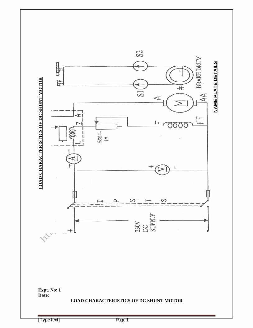
Expt. No: 1 Date:
LOAD CHARACTERISTICS OF DC SHUNT MOTOR
LOA
D C
HA
RA
CTE
RIS
TIC
S O
F D
C S
HU
NT
MO
TOR
NA
ME
PLA
TE D
ETA
ILS
ELECTRICAL MACHINES LABORATORY MANUAL 2
http://annauniversitystudymaterials.blogspot.in/
AIM: To conduct load test on a dc shunt motor and to draw its performance curves.
APPARATUS / INSTRUMENTS USED:
S.NO ITEM TYPE RANGE QUANTITY 1 Ammeter 2 Voltmeter 3 Rheostat 4 DPST Switch 5 Tachometer
FORMULAE: Input Voltage = V in Volts Input Current = I in Ampere Input Power, Pi = VI in Watts Spring balance readings = (S1-S2) in kg Speed of the motor = N in rpm
Radius of the brake drum = r in metres Torque, T =(S1~ S2) *r* 9.81 in N-m
Output Power, Po = 2 NT / 60 in Watts Percentage Efficiency = (Po / Pi) * 100 in %
THEORY: This is a direct method and consists of applying a brake to a water cooled pulley mounted on the motor shaft. The brake band is fixed with the help of metal frame with swivels gripping the pulley. A rope is wound round the pulley and its two ends are attached to the spring balances S1 and S2. One end of the band is fixed to earth via a spring balance S1 and the other end is fixed via another spring balance S2. The tension of the rope can be adjusted with the help of swivels. Obviously the force acting tangentially on the pulley is equal to the difference between the readings of the two spring balances. This test is applicable only to the small rated motors, because in large motors it is difficult to dissipate the heat. PRECAUTIONS: Ensure that there is no load on the motor. Armature resistance should be kept at maximum or starter can be used. The motor field rheostat should be in minimum position. At starting back EMF is zero as it depends on the speed of the motor.
ELECTRICAL MACHINES LABORATORY MANUAL 3
http://annauniversitystudymaterials.blogspot.in/
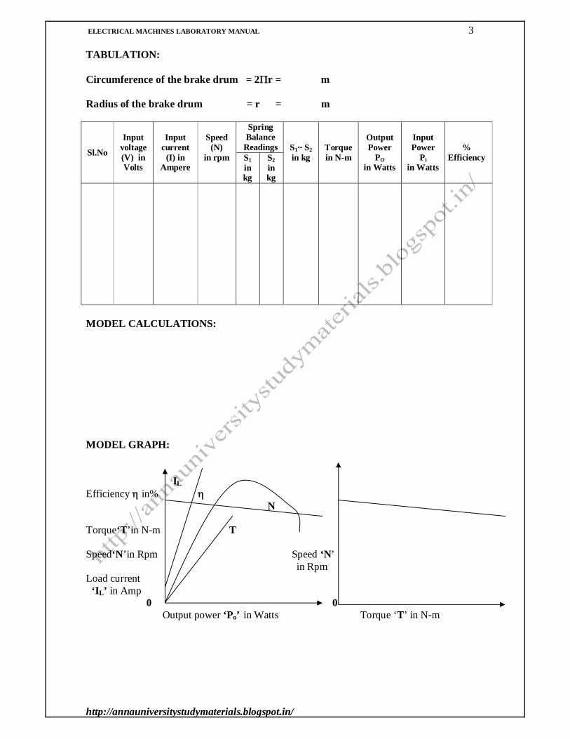
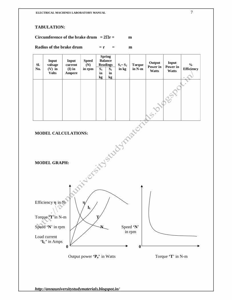
TABULATION: Circumference of the brake drum = 2r = m Radius of the brake drum = r = m
Sl.No
Input
voltage (V) in Volts
Input current
(I) in Ampere
Speed (N)
in rpm
Spring Balance
Readings S1~ S2 in kg
Torque in N-m
Output Power
PO in Watts
Input Power
Pi in Watts
% Efficiency S1
in kg
S2 in kg
MODEL CALCULATIONS: MODEL GRAPH: IL Efficiency in% N Torque‘T’in N-m T Speed‘N’in Rpm Speed ‘N’ in Rpm Load current ‘IL’ in Amp 0 0 Output power ‘Po’ in Watts Torque ‘T’ in N-m
ELECTRICAL MACHINES LABORATORY MANUAL 4
http://annauniversitystudymaterials.blogspot.in/
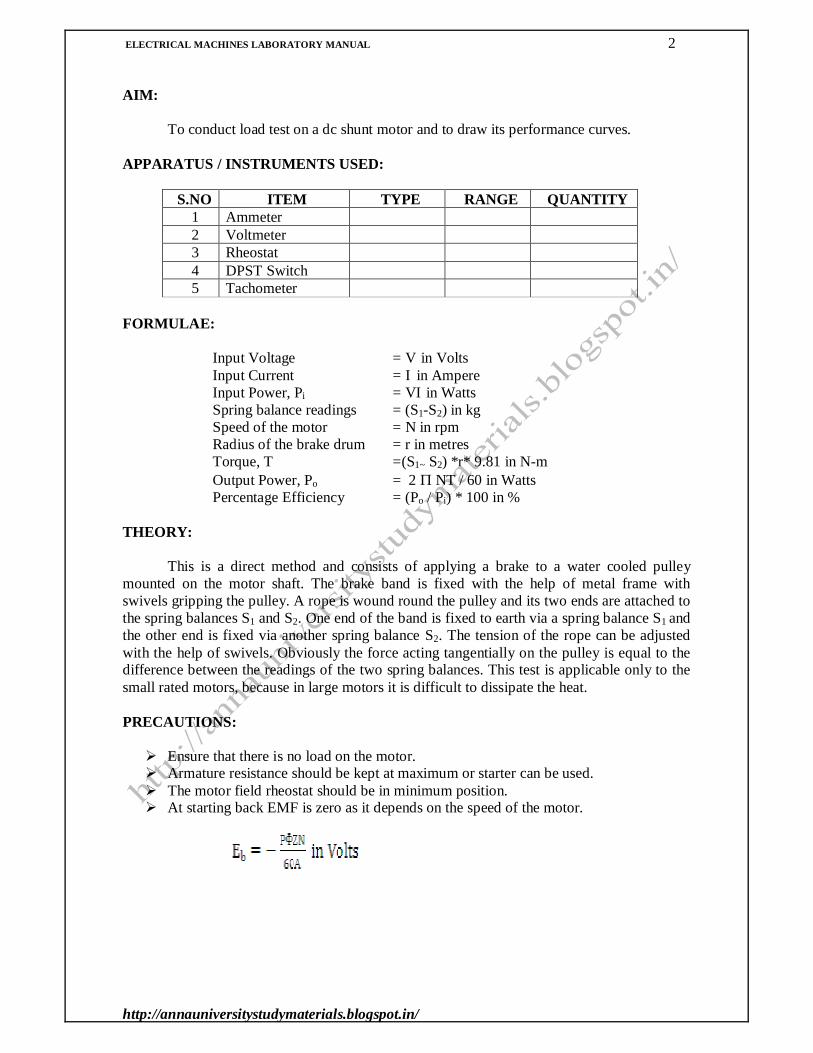
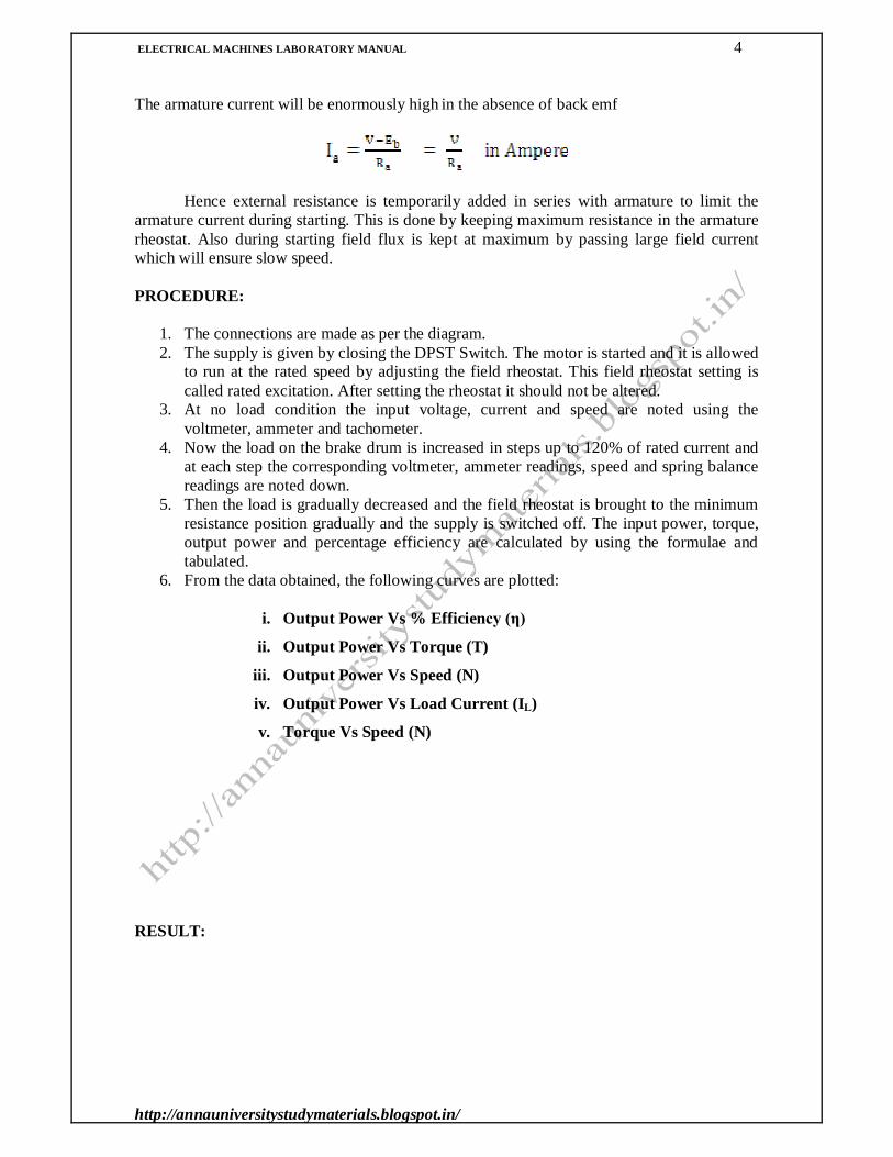
The armature current will be enormously high in the absence of back emf
Hence external resistance is temporarily added in series with armature to limit the
armature current during starting. This is done by keeping maximum resistance in the armature rheostat. Also during starting field flux is kept at maximum by passing large field current which will ensure slow speed.
PROCEDURE:
1. The connections are made as per the diagram. 2. The supply is given by closing the DPST Switch. The motor is started and it is allowed
to run at the rated speed by adjusting the field rheostat. This field rheostat setting is called rated excitation. After setting the rheostat it should not be altered.
3. At no load condition the input voltage, current and speed are noted using the voltmeter, ammeter and tachometer.
4. Now the load on the brake drum is increased in steps up to 120% of rated current and at each step the corresponding voltmeter, ammeter readings, speed and spring balance readings are noted down.
5. Then the load is gradually decreased and the field rheostat is brought to the minimum resistance position gradually and the supply is switched off. The input power, torque, output power and percentage efficiency are calculated by using the formulae and tabulated.
6. From the data obtained, the following curves are plotted:
i. Output Power Vs % Efficiency (η)
ii. Output Power Vs Torque (T)
iii. Output Power Vs Speed (N)
iv. Output Power Vs Load Current (IL)
v. Torque Vs Speed (N)
RESULT:

ELECTRICAL MACHINES LABORATORY MANUAL 5
http://annauniversitystudymaterials.blogspot.in/
NA
ME
PLA
TE D
ETA
ILS
LOA
D C
HA
RA
CTE
RIS
TIC
S O
F D
C S
ERIE
S M
OTO
R

ELECTRICAL MACHINES LABORATORY MANUAL 6
http://annauniversitystudymaterials.blogspot.in/
Expt. No: 2 Date:
LOAD CHARACTERISTICS OF DC SERIES MOTOR
AIM: To conduct the load test on a D.C. series motor and draw its performance characteristics. APPARATUS / INSTRUMENTS USED:
Sl.NO ITEM TYPE RANGE QUANTITY 1 Ammeter 2 Voltmeter 3 DPST Switch 4 Tachometer
FORMULAE Input Voltage = V in Volts Input Current = I in Ampere Input Power, Pi = VI in Watts Spring balance readings = (S1-S2) in kg Speed of the motor = N in rpm
Radius of the brake drum = r in metres Torque, T =(S1~ S2) *r* 9.81 in N-m
Output Power, Po = 2 NT / 60 in Watts Percentage Efficiency = (Po / Pi) * 100 in %
THEORY: This is a direct method and consists of applying a brake to a water cooled pulley mounted on the motor shaft. The brake band is fixed with the help of metal frame with swivels gripping the pulley. A rope is wound round the pulley and its two ends are attached to the spring balances S1 and S2. One end of the band is fixed to earth via a spring balance S1 and the other end is fixed via another spring balance S2. The tension of the rope can be adjusted with the help of swivels. Obviously the force acting tangentially on the pulley is equal to the difference between the readings of the two spring balances. This test is applicable only to the small rated motors, because in large motors it is difficult to dissipate the heat.
Care must be taken to see that the motor is always loaded with 3/4th full load before starting. The reason is as follows:
V-IaRa = Eb
At lighter loads, Ia is very small and negligible. Hence flux is small.
V= Eb=NΦ NΦ = Constant, K; N= K/Φ
Hence the speed N becomes dangerously high. With 3/4th load, Ia is large and hence the speed is within the limits.
ELECTRICAL MACHINES LABORATORY MANUAL 7
http://annauniversitystudymaterials.blogspot.in/
TABULATION: Circumference of the brake drum = 2r = m Radius of the brake drum = r = m
Sl.No.
Input
voltage (V) in Volts
Input current
(I) in Ampere
Speed (N)
in rpm
Spring Balance
Readings S1~ S2 in kg
Torque in N-m
Output Power in
Watts
Input Power in
Watts
% Efficiency S1
in kg
S2 in kg
MODEL CALCULATIONS: MODEL GRAPH: Efficiency in % IL Torque ‘T’in N-m T Speed ‘N’ in rpm N Speed ‘N’ in rpm Load current ‘IL’ in Amps 0 0 Output power ‘Po’ in Watts Torque ‘T’ in N-m

ELECTRICAL MACHINES LABORATORY MANUAL 8
http://annauniversitystudymaterials.blogspot.in/
PRECAUTION: Ensure that there is 3/4th load on the motor.
PROCEDURE
1. The connections are made as per the circuit diagram. 2. The supply is given by closing the DPST Switch. 3. The motor is started using the starter. 4. Now the load on the brake drum is increased in steps up to 120% of rated current and
the corresponding voltmeter, ammeter readings, speed and spring balance readings are noted down.
5. Then the load is gradually decreased step by step to the initial condition (with some load) and the supply is switched off.
6. The input power, torque, output power and percentage efficiency are calculated by using the formulae and tabulated.
7. From the data obtained, the following curves are plotted:
i. Output Power Vs % Efficiency (η)
ii. Output Power Vs Torque (T)
iii. Output Power Vs Speed (N)
iv. Output Power Vs Load Current (IL)
v. Torque Vs Speed (N)
RESULT:
ELECTRICAL MACHINES LABORATORY MANUAL 9
http://annauniversitystudymaterials.blogspot.in/
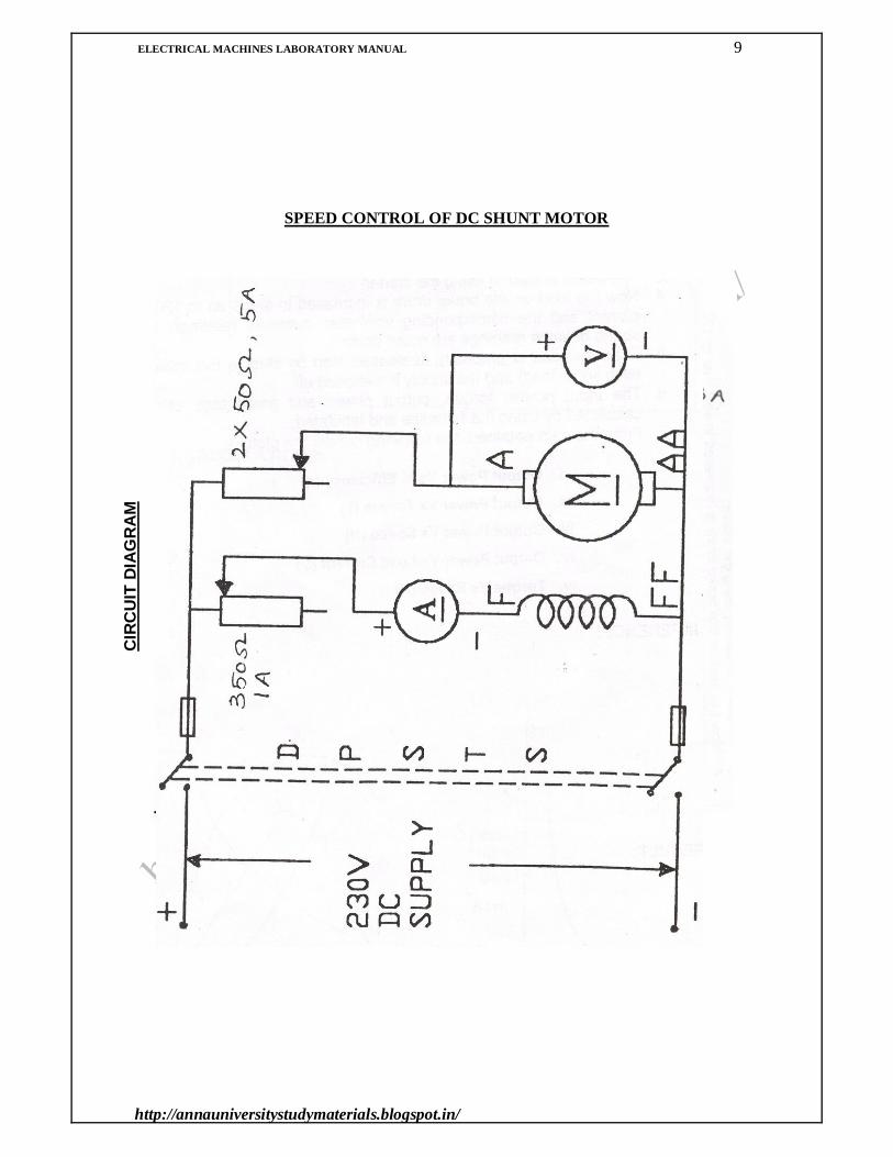
SPEED CONTROL OF DC SHUNT MOTOR
CIR
CU
IT D
IAG
RA
M
ELECTRICAL MACHINES LABORATORY MANUAL 10
http://annauniversitystudymaterials.blogspot.in/
Expt. No: 3 Date:
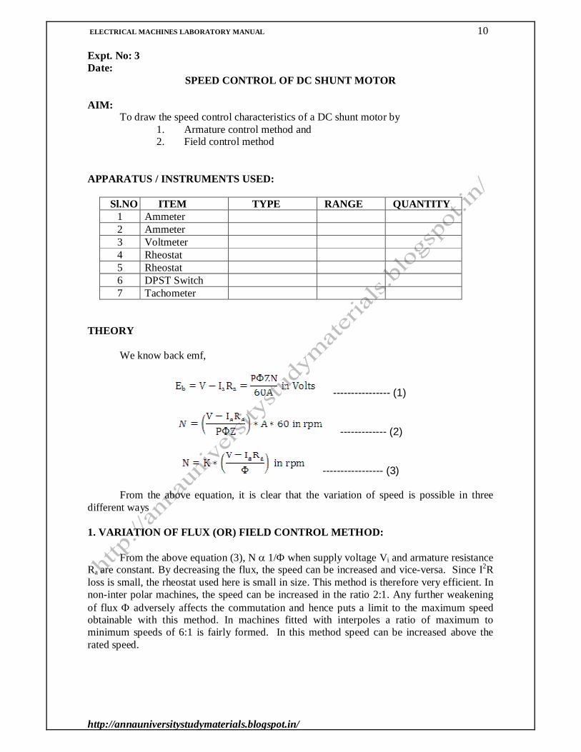
SPEED CONTROL OF DC SHUNT MOTOR AIM: To draw the speed control characteristics of a DC shunt motor by
1. Armature control method and 2. Field control method
APPARATUS / INSTRUMENTS USED:
Sl.NO ITEM TYPE RANGE QUANTITY 1 Ammeter 2 Ammeter 3 Voltmeter 4 Rheostat 5 Rheostat 6 DPST Switch 7 Tachometer
THEORY We know back emf,
---------------- (1)
------------- (2)
----------------- (3) From the above equation, it is clear that the variation of speed is possible in three different ways 1. VARIATION OF FLUX (OR) FIELD CONTROL METHOD: From the above equation (3), N 1/ when supply voltage Vi and armature resistance Ra are constant. By decreasing the flux, the speed can be increased and vice-versa. Since I2R loss is small, the rheostat used here is small in size. This method is therefore very efficient. In non-inter polar machines, the speed can be increased in the ratio 2:1. Any further weakening of flux adversely affects the commutation and hence puts a limit to the maximum speed obtainable with this method. In machines fitted with interpoles a ratio of maximum to minimum speeds of 6:1 is fairly formed. In this method speed can be increased above the rated speed.

ELECTRICAL MACHINES LABORATORY MANUAL 11
http://annauniversitystudymaterials.blogspot.in/
TABULATION: FIELD CONTROL METHOD:
Armature Voltage
Va in Volts
Sl. No.
Field Current If in Ampere
Speed N in rpm
1. 2. 3. 4. 5. 6.
1. 2. 3. 4. 5. 6.
ARMATURE CONTROL METHOD:
Field Current If in Ampere
Sl. No.
Armature Voltage
Va in Volts
Speed N in rpm
1. 2. 3. 4. 5. 6.
1. 2. 3. 4. 5. 6.

ELECTRICAL MACHINES LABORATORY MANUAL 12
http://annauniversitystudymaterials.blogspot.in/
2. ARMATURE (OR) RHEOSTATIC CONTROL METHOD: When flux is kept constant,
N = k1(V-IaRa) N1 = k1(V-IaRa1)
N2 = k1(V-IaRa2) This method is used when speeds below the no load speed are required. In this method
armature current is controlled by means of a variable rheostat in the armature circuit. 3. VOLTAGE CONTROL METHOD:
It is obvious that the speed can be varied by changing the voltage applied to the motor. N = k1(V-IaRa) N1 = k1(V1-IaRa1) N2 = k1(V2-IaRa2) The two commonly employed types are:
a) Multiple voltage control and b) Ward – Leonard system
PRECAUTIONS:
Armature resistance should be kept at maximum position. The motor field rheostat should be in minimum position. At starting back EMF is zero as it depends on the speed of the motor.
The armature current will be enormously high in the absence of back emf
Hence external resistance is temporarily added in series with armature to limit the armature current during starting. This is done by keeping maximum resistance in the armature rheostat. Also during starting, field flux is kept at maximum by passing large field current which will ensure slow speed. PROCEDURE:
1. Circuit connections are given as per the circuit diagram. 2. Supply is switched on and the armature rheostat is gradually decreased. 3. The field rheostat of the motor is adjusted to make it run at the rated speed.

ELECTRICAL MACHINES LABORATORY MANUAL 13
http://annauniversitystudymaterials.blogspot.in/
MODEL GRAPH: FIELD CONTROL CHARACTERISTICS ARMATURE CONTROL CHARACTERISTICS
Y axis
Speed in Va1 Va2 rpm Rated Speed X axis
Field Current If in Ampere
Y axis
Speed in rpm Rated Speed If1 If2 X axis
Armature Voltage in Volts

ELECTRICAL MACHINES LABORATORY MANUAL 14
http://annauniversitystudymaterials.blogspot.in/
FIELD CONTROL METHOD:
1. Armature voltage and hence armature current is kept constant at a particular value. 2. By adjusting the field rheostat, the field current is varied and the value of field
current and speed are noted. 3. The same procedure is repeated for another value of armature voltage and the
curve If Vs. N is plotted for the two values of armature voltage. ARMATURE CONTROL METHOD:
1. The field current is kept constant at a particular value. 2. By adjusting the armature rheostat, armature voltage is varied and the value of
armature voltage Va and speed N are noted. 3. The same procedure is repeated for another value of field current and the curve Va
Vs. N is plotted for the two values of field current. RESULT:

ELECTRICAL MACHINES LABORATORY MANUAL 15
http://annauniversitystudymaterials.blogspot.in/

ELECTRICAL MACHINES LABORATORY MANUAL 16
http://annauniversitystudymaterials.blogspot.in/
Expt. No: 4 Date:
LOAD TEST ON SINGLE PHASE TRANSFORMER
AIM: To conduct load test on the given single-phase transformer and to draw its performance characteristic curves. APPARATUS / INSTRUMENTS USED: Sl.NO ITEM TYPE RANGE QUANTITY
1 Ammeter 2 Ammeter 3 Voltmeter 4 Voltmeter
5 Wattmeter UPF
6 Single phase Auto Transformer 230 V/ (0-270) V 7 DPST Switch
FORMULAE:
Primary input power = W1 in Watts Secondary load voltage = V2 in Volts Secondary load current = I2 in Ampere Secondary power output = W2 in Watts % Efficiency = (Output Power / Input Power)*100
= (W2/W1)*100 Secondary no load voltage = V02 in Volts Secondary load voltage = V2 in Volts
% Regulation = (V02-V2/V02)*100 THEORY: EFFICIENCY:
Transformer is a static device by which electric power is transformed from one circuit to another circuit at the same frequency. Hence there are no friction or windage losses. The transformer consists of two separate windings placed over a laminated silicon steel core. The winding to which AC supply is connected is called primary winding and the winding to which load is connected is called secondary winding. When AC supply of voltage V1 is connected to primary winding, an alternating flux is set up in the core. This alternating flux when links with the secondary winding, an e.m.f. E2 is induced in it called mutually induced e.m.f. The direction of this induced e.m.f is opposite to the applied voltage according to Lenz’s law.
ELECTRICAL MACHINES LABORATORY MANUAL 17
http://annauniversitystudymaterials.blogspot.in/
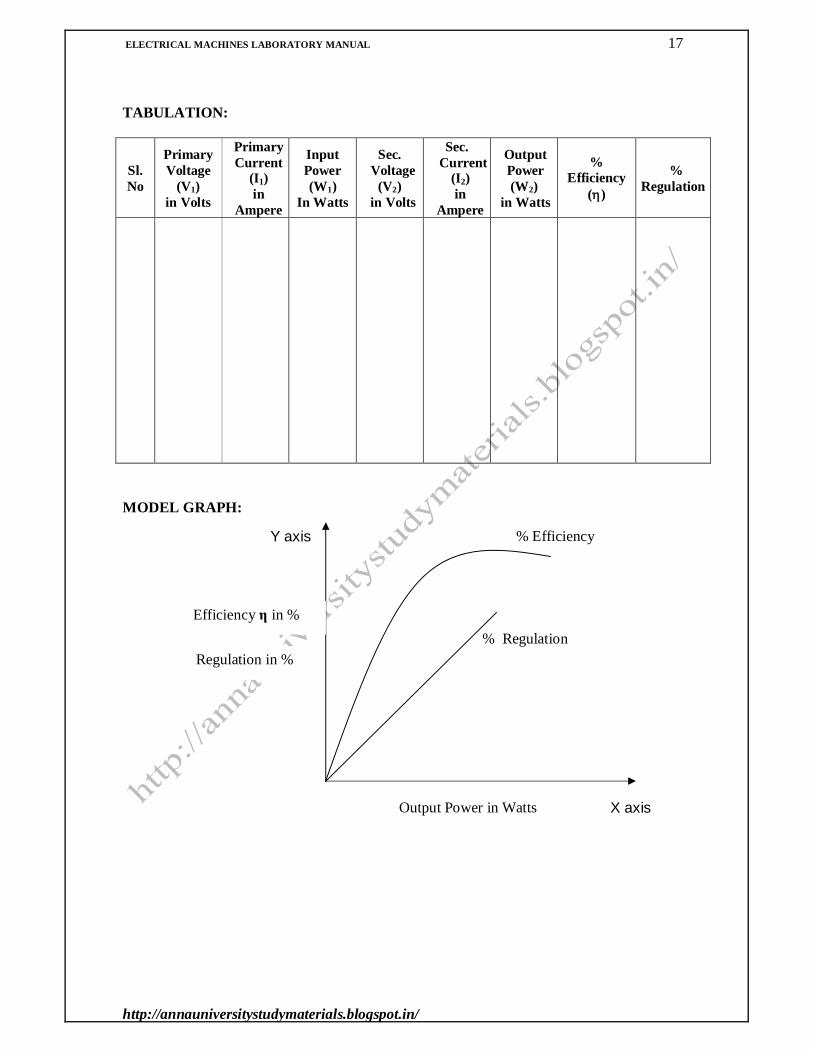
TABULATION:
Sl. No
Primary Voltage
(V1) in Volts
Primary Current
(I1) in
Ampere
Input Power (W1)
In Watts
Sec. Voltage
(V2) in Volts
Sec. Current
(I2) in
Ampere
Output Power (W2)
in Watts
% Efficiency
()
% Regulation
MODEL GRAPH:
Output Power in Watts
Efficiency η in %
Regulation in % % Regulation
% Efficiency
X axis
Y axis

ELECTRICAL MACHINES LABORATORY MANUAL 18
http://annauniversitystudymaterials.blogspot.in/
The same alternating flux also links with the primary winding and produces self induced e.m.f E1.This induced e.m.f. E1 also acts in opposite direction to the applied voltage V1. The Induced e.m.f in primary is proportional to number of turns of the primary winding N1. The induced e.m.f in the secondary is proportional to number of turns of the secondary winding N2. In case N2 > N1, the transformer is step up transformer. When N2 < N1, the transformer is step down transformer. The losses in the transformer are Core loss or Iron loss. This includes both hysterisis and eddy current losses.
The Efficiency can be calculated by observing the input power and the output power for various loads. REGULATION:
Regulation is an important parameter by which the performance of a transformer can be assessed. The lesser the regulation, the better is the transformer efficiency because a good transformer should keep its secondary terminal voltage as constant equal as possible under all conditions of load. When a transformer is loaded with a constant primary voltage, the secondary voltage decreases (assuming lagging p.f. loads) because of its internal resistance and leakage reactance.
Secondary no load voltage = V02 in Volts Secondary load voltage = V2 in Volts % Regulation = (V02 - V2)/ V02*100 PROCEDURE:
1. Circuit Connections are made as per the circuit diagram. 2. Keeping the secondary side DPST switch open, rated AC voltage is applied to the
primary of the transformer. 3. The no load voltage across the secondary and primary side of the transformer are noted
down. 4. Now the DPST switch across the load is closed. 5. The load current is increased in steps. 6. The primary voltage V1, secondary voltage V2, primary current I1, secondary current I2,
primary power input W1 and secondary power output W2 are noted and tabulated. 7. The readings are taken upto 1.25 times the full load.
RESULT:

ELECTRICAL MACHINES LABORATORY MANUAL 19
http://annauniversitystudymaterials.blogspot.in/
SHORT CIRCUIT TEST ON SINGLE PHASE TRANSFORMER

ELECTRICAL MACHINES LABORATORY MANUAL 20
http://annauniversitystudymaterials.blogspot.in/
Expt. No: 5 Date:
OPEN CIRCUIT TEST (OCT) AND SHORT CIRCUIT TEST (SCT) ON
SINGLE PHASE TRANSFORMER AIM:
To conduct open circuit and short circuit tests on a single phase transformer and to determine the equivalent circuit parameters. APPARATUS / INSTRUMENTS USED:
Sl.NO ITEM TYPE RANGE QUANTITY 1 Ammeter 2 Ammeter 3 Voltmeter 4 Voltmeter 5 Wattmeter LPF(OCT) 6 Wattmeter UPF(SCT)
7 Single phase Auto Transformer
230 V/ (0-270) V
8 DPST Switch FORMULAE: OPEN CIRCUIT TEST:
No load supply voltage = Vo in Volts No load primary current = Io in Ampere No load power input W0 =VoIoCos o in Watts No load power factor Cos o = W0 / VoIo Core loss component of no load current Iw = IoCos o in Ampere Magnetizing component of no load current I =Io sin o in Ampere No load resistance Ro = Vo /Iw in Ohms No load Magnetizing reactance Xo = Vo/I in Ohms
SHORT CIRCUIT TEST: Voltage at the primary to circulate rated current at short circuit = Vsc in Volts Rated primary current at short circuit = Isc in Ampere Primary power input to the at short circuit = Wsc= Isc
2 * R01 in Watts Equivalent resistance referred to primary R01 = Wsc / Isc
2 in Ohms Equivalent reactance referred to Primary X01 = (Z01
2-R012)1/2
in Ohms Equivalent impedance referred to primary Z01 = Vsc / Isc in Ohms Full- load copper loss Pc = Wsc in Watts

ELECTRICAL MACHINES LABORATORY MANUAL 21
http://annauniversitystudymaterials.blogspot.in/
OPEN CIRCUIT TEST ON SINGLE PHASE TRANSFORMER

ELECTRICAL MACHINES LABORATORY MANUAL 22
http://annauniversitystudymaterials.blogspot.in/
THEORY:
Transformer is a static device that transforms power from one circuit to the other circuit at the same frequency. The basic principle involved is mutual induction. Hence there are no friction or windage losses. The transformer consists of two separate windings placed over a laminated silicon steel core. The winding to which AC supply is connected is called primary winding and the winding to which load is connected is called secondary winding.
When AC supply of voltage V1 is connected to primary winding, an alternating flux is set up in the core. This alternating flux when links with the secondary winding, an e.m.f. E2 is induced in it called mutually induced e.m.f. The direction of this induced e.m.f is opposite to the applied voltage according to Lenz’s law. The same alternating flux also links with the primary winding and produces self induced e.m.f E1.This induced e.m.f. E1 also acts in opposite direction to the applied voltage V1. The Induced e.m.f in primary is proportional to number of turns of the primary winding N1. The induced e.m.f in the secondary is proportional to number of turns of the secondary winding N2. In case N2 > N1, the transformer is step up transformer. When N2 < N1, the transformer is step down transformer. The losses in the transformer are Core loss or Iron loss. This includes both hysterisis and eddy current losses. OPEN CIRCUIT TEST:
As the name implies, the secondary (High Voltage side) is kept open. Primary is given with rated voltage. Due to the flux set up in the core, maximum iron losses will occur. As the primary current is small (usually 2 to 10% of rated load current), copper losses will be negligibly small in primary and in secondary (opened). Hence power consumed under open circuit is practically core-loss which remains constant for all the loads.
SHORT CIRCUIT TEST: This is an economical method of testing the transformer without conducting load test. The following parameters are determined from this test.
Equivalent impedance referred to the primary (Zo1) in Ohms Equivalent impedance referred to the secondary (Zo2) in Ohms Leakage reactance referred to the primary (Xo1) in Ohms Leakage reactance referred to the secondary (Xo2) in Ohms Total resistance referred to the primary (Ro1) in Ohms Total resistance referred to the secondary (Ro2) in Ohms
Copper loss at full load (or at any known fraction of full load) is determined by this
test. This loss is used in calculating the efficiency of the transformer. The total voltage drop in the transformer as referred to primary or secondary can be calculated from Zo1or Zo2 and hence regulation of the transformer is determined.
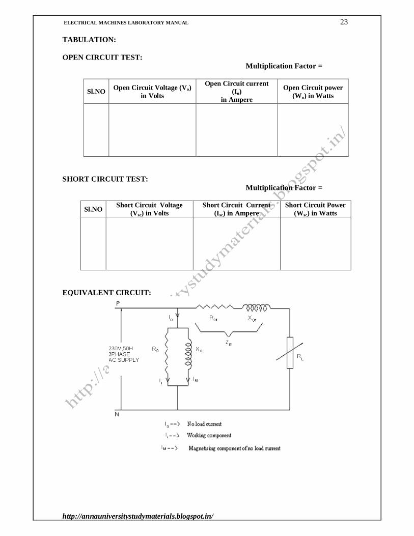
EQUIVALENT CIRCUIT:
The equivalent circuit of a transformer is as shown in Fig.1. It consists of two circuits (i) Magnetizing circuit consisting of Ro and Xo.
(ii)Working circuit consisting of Ro1, Xo1 and load ZL.
ELECTRICAL MACHINES LABORATORY MANUAL 23
http://annauniversitystudymaterials.blogspot.in/
TABULATION: OPEN CIRCUIT TEST: Multiplication Factor =
Sl.NO Open Circuit Voltage (Vo) in Volts
Open Circuit current (Io)
in Ampere
Open Circuit power (Wo) in Watts
SHORT CIRCUIT TEST:
Multiplication Factor =
Sl.NO Short Circuit Voltage (Vsc) in Volts
Short Circuit Current (Isc) in Ampere
Short Circuit Power (Wsc) in Watts
EQUIVALENT CIRCUIT:

ELECTRICAL MACHINES LABORATORY MANUAL 24
http://annauniversitystudymaterials.blogspot.in/
The above four quantities namely Ro, Xo, Ro1and Xo1 are known as Parameters or Constants of transformer. Ro, Xo can be found out with the help of open circuit test and Ro1and Xo1 by short circuit test. Once we know these quantities the performance of the transformer such as efficiency, regulation etc can be determined at any desired load and power factor. PROCEDURE: 1. OPEN CIRCUIT TEST:
1. Circuit Connections are made as per the circuit diagram. 2. The rated voltage is applied to the primary of the transformer with secondary kept
open. 3. This is an open circuit test. Primary takes no load current which is measured by
appropriate ammeter. 4. At no load the power factor of the transformer will be very low. Hence the no load
power input is measured by a low power factor wattmeter. 5. The observed readings are tabulated. 6. Calculations are done using the formulae.
2. SHORT CIRCUIT TEST:
1. Before starting the experiment, the secondary of the transformer is short circuited and the other connections are made as per the circuit diagram.
2. The supply is switched on and the DPST switch is closed. 3. The auto transformer is adjusted to increase the voltage so that the rated primary
current flows in the circuit. Because of this, core losses are very small with the result that wattmeter reading represents full load copper-loss for the whole transformer.
4. The primary voltage, short circuit current and the wattmeter reading are noted down and tabulated.
5. Calculations are done by using the formulae and the equivalent circuit is drawn.

ELECTRICAL MACHINES LABORATORY MANUAL 25
http://annauniversitystudymaterials.blogspot.in/
MODEL CALCULATIONS: Rated power output = Po in Watts =
Constant loss, Wc = W0 - Io2 * R01 in Watts =
Efficiency at ½ full load
At ½ full load copper loss = Wsc * (½) 2 = Wsc / 4 in Watts =
Output power at 1/2 full load = Po / 2 in Watts = Input power, Pi = Power output + copper loss + constant loss
= (Po / 2)+ (Wsc/ 4) + Wc in Watts = Efficiency = (Po / 2) / Pi * 100 % =
Efficiency at full load
At full load copper loss = Wsc in Watts = Output power at full load = Po in Watts =
Input power, Pi = Power output + copper loss + constant loss = Po+ Wsc+ Wc in Watts = Efficiency = (Po / Pi) * 100 % =
Regulation
Equivalent impedance referred to primary Z01 = Vsc / Isc in Ohms =
Equivalent resistance referred to primary R01 = Wsc / Isc2 in Ohms =
Equivalent reactance referred to Primary X01 = (Z01
2-R012)1/2 in Ohms =
Power factor of the load = Cos = Secondary load voltage = V2 in Volts = Load current at which regulation is considered I1
Regulation at load current =[ I1 (R01 Sin + X01 Cos ) / V2 ] x 100 % =

ELECTRICAL MACHINES LABORATORY MANUAL 26
http://annauniversitystudymaterials.blogspot.in/
RESULT:

ELECTRICAL MACHINES LABORATORY MANUAL 27
http://annauniversitystudymaterials.blogspot.in/
LOAD CHARACTERISTICS OF DC SEPARATELY EXCITED GENERATOR
Expt. No: 6

ELECTRICAL MACHINES LABORATORY MANUAL 28
http://annauniversitystudymaterials.blogspot.in/
Exp No: 6 Date:
LOAD CHARACTERISTICS OF
DC SEPARATELY EXCITED GENERATOR
AIM: To conduct no load and load tests on a DC separately excited generator and to obtain
the characteristics. APPARATUS / INSTRUMENTS USED:
S.NO ITEM TYPE RANGE QUANTITY 1 Ammeter 2 Voltmeter 3 Rheostat Wire Wound 4 Rheostat Wire Wound 5 SPST Switch 6 DPST Switch 7 Tachometer Digital 8 Loading Rheostat Wire Wound
FORMULAE: Generated emf, Eg = Vt+IaRa (Volts) and Ia = IL (Amps) at no load condition IL = 0 so Eg = Vt
Where Vt – Terminal Voltage in Volts Ia – Armature current in Amps
Ra – Armature Resistance in Ohms IL – Load current in Amps
THEORY: OPEN CIRCUIT CHARACTERISTICS (O.C.C.):
The O.C.C. may be called as No Load or Magnetization Characteristics. It shows the
relation between the no load generated emf in the armature, E0 and the field current If at a given fixed speed. It’s shape is practically the same for all generators whether separately excited or self excited.
With reference to the model graph, it may be stated that due to residual magnetism in
the poles, some emf is generated even when If = 0. Hence the curve starts a little value from the origin up. The slight curvature at the lower end is due to magnetic inertia. It is seen that the first part of the curve is practically straight line. This is due to the fact that at low flux densities, reluctance of iron path being negligible (due to high permeability). Total reluctance is given by the air-gap reluctance which is constant. Hence the flux and consequently the generated emf is directly proportional to the exciting field current. However at high flux densities, where is small iron path reluctance becomes appreciable and the straight relation between E0 and If no longer holds good. In other words, after point B, saturation of poles starts. It should be noted that O.C.C. at higher speed would be above the reference curve at lower speed, it would be below the curve.

ELECTRICAL MACHINES LABORATORY MANUAL 29
http://annauniversitystudymaterials.blogspot.in/
TABULATION: OPEN CIRCUIT CHARACTERISTICS:
Sl.No. Field Current If in Ampere Eg = Terminal Voltage Vt in Volts
LOAD CHARACTERISTICS: No Load Voltage (VNo Load) = Volts
TO FIND ARMATURE RESISTANCE:
MODEL CALCULATIONS: MODEL GRAPH: Open Circuit Characteristics Load Characteristics
Sl.No. Terminal Voltage
Vt in Volts
Field current If in Ampere
Load Current IL in Ampere
Ia * Ra in Volts
Generated emf Eg in Volts
Voltage Regulation
in %
Sl.No. Armature Current Ia in Ampere
Armature Voltage
Va in Volts
Armature Resistance Ra = Va / Ia in Ohms
IL (Ampere)
VT, Eg (Volts)
IaRa
VT Eg
Eg (Volts)
If (Ampere)

ELECTRICAL MACHINES LABORATORY MANUAL 30
http://annauniversitystudymaterials.blogspot.in/
CRITICAL RESISTANCE: The value of the field resistance at which the generator fails to excite or fails to build up the voltage is called critical resistance. LOAD CHARACTERISTICS:
Let E0 be the no load voltage at rated speed for a certain field current. If there were no armature reaction and armature voltage drop, then this voltage would have remained constant as shown by the dotted line. But when the generator is loaded, the voltage falls thereby giving slightly drooping characteristics. If we subtract from E0 the value of voltage drops due to armature reaction for different loads, then we get the value of E, the emf actually induced in the armature under load conditions. Curve II is plotted in this way and is known as internal characteristics. The straight line OA represents the IaRa. Curve III represents the external characteristics. VOLTAGE REGULATION:
Voltage regulation is used to indicate the degree of change in armature voltage produced by application of load. It is defined as the change in voltage from no load to full load expressed as a percentage of rated terminal voltage.
PRECAUTIONS: Armature resistance should be kept at maximum or starter can be used. The motor field rheostat should be in minimum position. At starting back EMF is zero as it depends on the speed of the motor.
The armature current will be enormously high in the absence of back emf
Hence external resistance is temporarily added in series with armature to limit the armature current during starting. This is done by keeping maximum resistance in the armature rheostat. Also during starting field flux is kept at maximum by passing large field current which will ensure slow speed. The generator field rheostat should be in maximum position.
PROCEDURE: 1. Connections are given as per the circuit diagram. 2. Initially field DPSTS is kept open. Load side DPSTS is kept open. Supply is given
and the motor is started with the help of a starter. 3. The field rheostat of the motor is adjusted to make it run at the rated speed. The
generator field DPSTS is closed.

ELECTRICAL MACHINES LABORATORY MANUAL 31
http://annauniversitystudymaterials.blogspot.in/
4. By varying the field rheostat in the generator side, different values of generated emf, Eg and field current If are noted from voltmeter and ammeter till the rated voltage of the generator. By using the above readings, the O.C.C is plotted.
5. To find critical resistance, a tangent is drawn to the initial portion of O.C.C. The slope of this curve gives the critical resistance for the speed at which the data was obtained.
6. Now the load side DPSTS is closed and the resistive load is switched on and increased in steps. The terminal voltage, armature and load current values are noted down for each step from the respective meters. Generators may be loaded up to 120 % of the rated current. From the above readings, load characteristics are plotted and voltage regulation is calculated.
TO FIND ARMATURE RESISTANCE:
1. Connections are given as per the circuit diagram. 2. Supply is switched on. 3. By varying the loading rheostat the ammeter and voltmeter readings are noted for
five gradual loads. 4. From these values the average value of DC armature resistance is calculated.
RESULT:

ELECTRICAL MACHINES LABORATORY MANUAL 32
http://annauniversitystudymaterials.blogspot.in/
ELECTRICAL MACHINES LABORATORY MANUAL 33
http://annauniversitystudymaterials.blogspot.in/

ELECTRICAL MACHINES LABORATORY MANUAL 34
http://annauniversitystudymaterials.blogspot.in/
Expt. No: 7 Date:
LOAD CHARACTERISTICS OF DC SHUNT GENERATOR
AIM:
To conduct no load and load tests on a DC self excited shunt generator and to obtain the characteristics. APPARATUS / INSTRUMENTS USED:
S.NO ITEM TYPE RANGE QUANTITY 1 Ammeter 2 Voltmeter 3 Rheostat Wire Wound 4 Rheostat Wire Wound 5 SPST Switch 6 DPST Switch 7 Tachometer Digital 8 Loading Rheostat Wire Wound
FORMULAE: Generated emf, Eg = Vt+IaRa (Volts) and Ia = IL+ If (Ampere)
Where Vt – Terminal Voltage in Volts Ia – Armature current in Amps
Ra – Armature Resistance in Ohms IL – Load current in Ampere If – Field current in Ampere
THEORY: OPEN CIRCUIT CHARACTERISTICS (O.C.C.):
The O.C.C. may be called as No Load or Magnetization Characteristics. It shows the
relation between the no load generated emf in the armature, E0 and the field current If at a given fixed speed. It’s shape is practically the same for all generators whether separately excited or self excited.
With reference to the model graph, it may be stated that due to residual magnetism in
the poles, some emf is generated even when If=0. Hence the curve starts a little value from the origin up. The slight curvature at the lower end is due to magnetic inertia. It is seen that the first part of the curve is practically straight line. This is due to the fact that at low flux densities, reluctance of iron path being negligible (due to high permeability). Total reluctance is given by the air-gap reluctance which is constant. Hence the flux and consequently the generated emf is directly proportional to the exciting field current. However at high flux densities, where is small iron path reluctance becomes appreciable and the straight relation between E0 and If no longer holds good. In other words, after point B, saturation of poles starts. It should be noted that O.C.C. at higher speed would be above the reference curve at lower speed, it would be below the curve.
ELECTRICAL MACHINES LABORATORY MANUAL 35
http://annauniversitystudymaterials.blogspot.in/
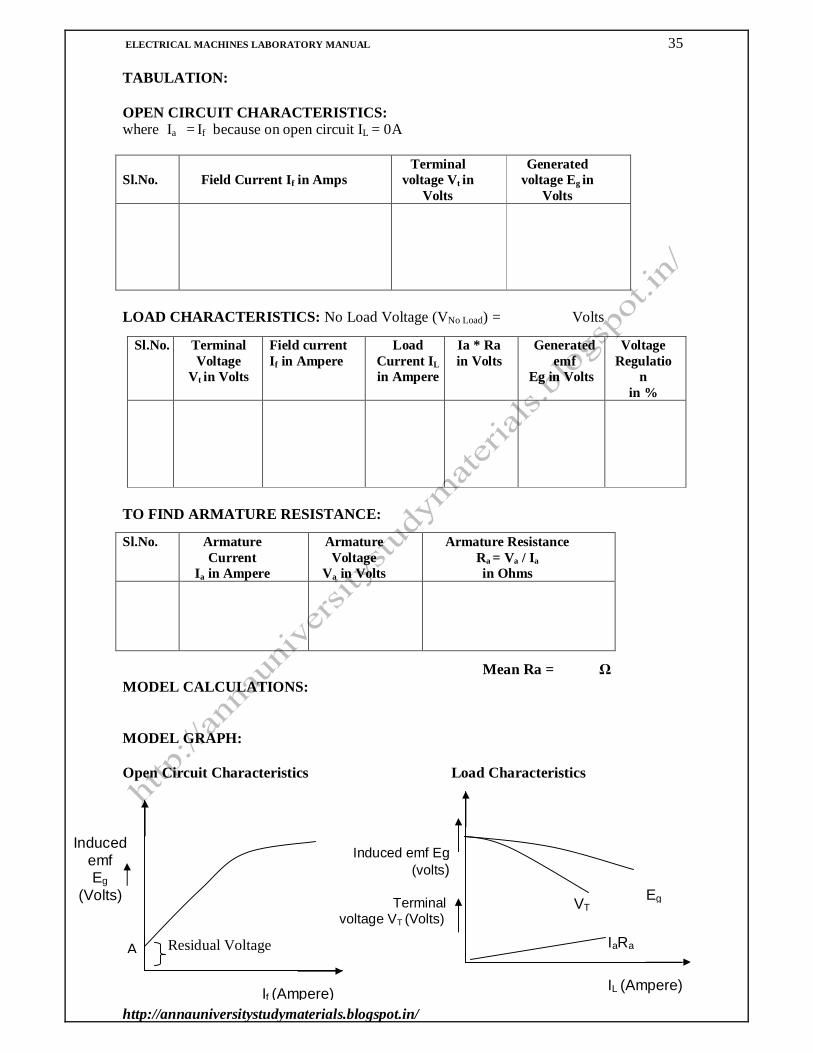
TABULATION: OPEN CIRCUIT CHARACTERISTICS: where Ia = If because on open circuit IL = 0A
Sl.No. Field Current If in Amps Terminal
voltage Vt in Volts
Generated voltage Eg in
Volts
LOAD CHARACTERISTICS: No Load Voltage (VNo Load) = Volts
TO FIND ARMATURE RESISTANCE:
Mean Ra = Ω MODEL CALCULATIONS: MODEL GRAPH: Open Circuit Characteristics Load Characteristics Residual Voltage
Sl.No. Terminal Voltage
Vt in Volts
Field current If in Ampere
Load Current IL in Ampere
Ia * Ra in Volts
Generated emf
Eg in Volts
Voltage Regulatio
n in %
Sl.No. Armature Current
Ia in Ampere
Armature Voltage
Va in Volts
Armature Resistance Ra = Va / Ia in Ohms
IaRa
VT Eg
IL (Ampere)
Induced emf Eg (volts)
Terminal voltage VT (Volts)
Induced emf Eg
(Volts)
If (Ampere)
A

ELECTRICAL MACHINES LABORATORY MANUAL 36
http://annauniversitystudymaterials.blogspot.in/
CRITICAL RESISTANCE: The value of the field resistance at which the generator fails to excite or fails to build up the voltage is called critical resistance. LOAD CHARACTERISTICS:
Let E0 be the no load voltage at rated speed for a certain field current. If there were no armature reaction and armature voltage drop, then this voltage would have remained constant as shown by the dotted line. But when the generator is loaded, the voltage falls thereby giving slightly drooping characteristics. If we subtract from E0 the value of voltage drops due to armature reaction for different loads, then we get the value of E, the emf actually induced in the armature under load conditions. Curve II is plotted in this way and is known as INTERNAL CHARACTERISTICS. The straight line OA represents the IaRa. Curve III represents the EXTERNAL CHARACTERISTICS. VOLTAGE REGULATION:
Voltage regulation is used to indicate the degree of change in armature voltage produced by application of load. It is defined as the change in voltage from no load to full load expressed as a percentage of rated terminal voltage.
PRECAUTIONS: Armature resistance should be kept at maximum or starter can be used. The motor field rheostat should be in minimum position. At starting back EMF is zero as it depends on the speed of the motor.
The armature current will be enormously high in the absence of back emf
Hence external resistance is temporarily added in series with armature to limit the armature current during starting. This is done by keeping maximum resistance in the armature rheostat. Also during starting field flux is kept at maximum by passing large field current which will ensure slow speed. The generator field rheostat should be in maximum position PROCEDURE:
7. Connections are given as per the circuit diagram. 8. Initially field SPSTS is kept open. Load side DPSTS is kept open. Supply is given
and the motor is started with the help of a starter. 9. The field rheostat of the motor is adjusted to make it run at the rated speed.

ELECTRICAL MACHINES LABORATORY MANUAL 37
http://annauniversitystudymaterials.blogspot.in/
10. With SPSTS in the generated field circuit kept open, the voltage generated due to residual magnetism is noted down. Then SPSTS is closed. If the residual voltage decreases it indicates the field current opposes the residual flux. Then the generator field terminals are interchanged to reverse the field current through it. Now the generator voltage will be higher than residual voltage. The generator field current is further increased in steps by adjusting the field rheostat and each time generator voltage is noted down and tabulated till the rated voltage of the generator. By using the above readings, the O.C.C is plotted.
11. To find critical resistance, a tangent is drawn to the initial portion of O.C.C. The slope of this curve gives the critical resistance for the speed at which the data was obtained.
12. Now the load side DPSTS is closed and the resistive load is switched on and increased in steps. The terminal voltage, armature and load current values are noted down for each step from the respective meters. Generators may be loaded up to 120 % of the rated current. From the above readings, load characteristics are plotted.
TO FIND ARMATURE RESISTANCE:
5. Connections are given as per the circuit diagram. 6. Supply is switched on. 7. By varying the loading rheostat the ammeter and voltmeter readings are noted for
five gradual loads. 8. From these values the average value of DC armature resistance is calculated.
RESULT:

ELECTRICAL MACHINES LABORATORY MANUAL 38
http://annauniversitystudymaterials.blogspot.in/
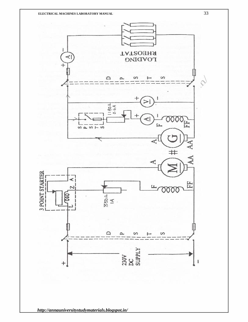
CIRCUIT DIAGRAM:
REGULATION OF ALTERNATOR BY EMF AND MMF METHODS
ELECTRICAL MACHINES LABORATORY MANUAL 39
http://annauniversitystudymaterials.blogspot.in/
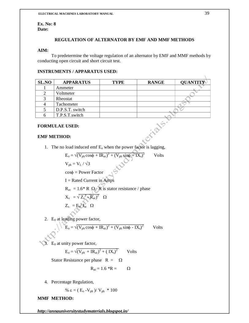
Ex. No: 8 Date:
REGULATION OF ALTERNATOR BY EMF AND MMF METHODS
AIM:
To predetermine the voltage regulation of an alternator by EMF and MMF methods by conducting open circuit and short circuit test.
INSTRUMENTS / APPARATUS USED: SL.NO APPARATUS TYPE RANGE QUANTITY
1 Ammeter 2 Voltmeter 3 Rheostat 4 Tachometer 5 D.P.S.T. switch 6 T.P.S.T.switch
FORMULAE USED: EMF METHOD:
1. The no load induced emf Eo when the power factor is lagging,
Eo = (Vph cos + IRac)2 + (Vph sin + IXs)2 Volts
Vph = VL / 3
cos = Power Factor
I = Rated Current in Amps
Rac = 1.6* R , R is stator resistance / phase
Xs = Zs2 - Rac)2
Zs = Eo/ Isc
2. E0 at leading power factor,
Eo = (Vph cos + IRac)2 + (Vph sin - IXs)2 Volts
3. E0 at unity power factor,
Eo = (Vph + IRac)2 + ( IXs)2 Volts
Stator Resistance per phase R =
Rac = 1.6 *R =
4. Percentage Regulation,
% = ( Eo -Vph )/ Vph * 100
MMF METHOD:

ELECTRICAL MACHINES LABORATORY MANUAL 40
http://annauniversitystudymaterials.blogspot.in/
5. If at lagging Power Factor,
If = (If 1+ If 2 sin)2 + (If 2 cos)2 Amps
6. If at lagging Power Factor,
If = (If 1 - If 2 sin)2 + (If 2 cos)2 Amps
7. If at unity Power Factor,
If = If 12 + If 2
2 Amps
where If 1 = Field current at rated voltage in open circuit test in amps If 2 = Field current at rated voltage in short circuit test in amps
THEORY:
Alternator is an alternating current generator. It works on the principle of
electromagnetic induction. Alternators have no commutator, as they are required to supply electrical energy with an alternating voltage. Therefore it is not necessary that the armature be the rotating member.
Alternators according to their construction are divided into the following two classifications:
1. Revolving- Armature type 2. Revolving- Field type
Revolving- Armature type Alternator: It has stationary field poles and revolving armature. It is usually of relatively low KVA capacity and low voltage rating. It resembles a D.C. generator in general appearance expect that it has slip rings instead of commutator. The field excitation must be direct current and therefore, must be supplied from an external direct current source. Revolving- Field type Alternator:
It has stationary armature or stator, instead of which the field poles rotate. Most alternators are of the revolving- field type, in which the revolving field structure or rotor has slip rings and brushes to supply the excitation current from an outside D.C. source. The armature coils are placed in slots in a laminated core called the stator.

ELECTRICAL MACHINES LABORATORY MANUAL 41
http://annauniversitystudymaterials.blogspot.in/
OBSERVATION: OPEN CIRCUIT TEST:
Sl.No Field
Current If (Amps)
Open Circuit Voltage VL
(Volts)
Phase Voltage Vph,
(Volts)
SHORT CIRCUIT TEST:
Sl.No
Short Circuit Current
ISC(Amps)
Field Current If (Amps)
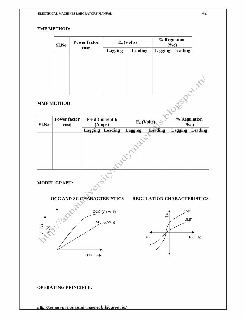
TABULATION: EMF METHOD:
Sl.No. Power factor cos
Eo (Volts) % Regulation (%)
Lagging Leading Lagging Leading
TABULATION:
ELECTRICAL MACHINES LABORATORY MANUAL 42
http://annauniversitystudymaterials.blogspot.in/
EMF METHOD:
Sl.No. Power factor cos
Eo (Volts) % Regulation (%)
Lagging Leading Lagging Leading
MMF METHOD:
Sl.No. Power factor
cos Field Current If
(Amps) Eo (Volts) % Regulation (%)
Lagging Leading Lagging Leading Lagging Leading
MODEL GRAPH:
OCC AND SC CHARACTERISTICS REGULATION CHARACTERISTICS OPERATING PRINCIPLE:
OCC (Vph vs If)
SC (ISC vs If)
Vph
(V)
I SC(A
)
If (A)
EMF
MMF
%
PF (Lag) PF (Lead)

ELECTRICAL MACHINES LABORATORY MANUAL 43
http://annauniversitystudymaterials.blogspot.in/
When the rotor rotates, the stator conductors being stationary are cut by the magnetic flux, hence the have induced emf produced in them. Because the magnetic poles are alternately N and S, they induce an emf and hence current in armature conductors, which first flows in one direction and then in the others. Hence alternating emf is produced in the stator conductors whose frequency depends on the number of N and S pole moving past a conductor in one second and whose direction is given by Fleming’s right –hand rule.
In case of an alternator, which has two poles, the induced emf passes through one complete revolution in one revolution of the machine. Therefore in a machine with p-poles, the number of cycle of emf in one revolution will be p/2. If a machine has a speed of N revolution per minute, the frequency will be
f = (p/2) * NS /60 per second
thus, f = (NS * p)/120 Hz
PROCEDURE: OPEN CIRCUIT TEST
1. The circuit connections are made as per the circuit diagram. 2. The prime mover is started and made to run at its rated speed of alternator by adjusting
the field rheostat of motor. 3. The alternator field is excited by closing the DPST. 4. By adjusting the alternator field rheostat the voltage across the armature is gradually
increased to its rated speed. 5. The corresponding terminal voltage and field current are noted. 6. The procedure is repeated till the rated voltage of the alternator. 7. The open circuit characteristics are drawn, by taking the field current along ‘X’ axis
and voltage along ‘y’ axis. SHORT CIRCUIT TEST
1. The circuit connections are made as per the circuit diagram. 2. The supply is switched ON. 3. By adjusting the alternator field rheostat, the rated current of the alternator is
circulated and the corresponding field current is noted. 4. After the readings are taken at rated current, the mechanical load is gradually removed,
the auto transformer is brought to initial condition and the supply is switched OFF. RESULT: CIRCUIT DIAGRAM:

ELECTRICAL MACHINES LABORATORY MANUAL 44
http://annauniversitystudymaterials.blogspot.in/
LOAD TEST ON THREE PHASE INDUCTION MOTOR

ELECTRICAL MACHINES LABORATORY MANUAL 45
http://annauniversitystudymaterials.blogspot.in/
Ex. No: 9 Date:
LOAD TEST ON THREE PHASE INDUCTION MOTOR
AIM:
To determine the performance characteristics of the given three-phase squirrel cage induction mo by direct loading.
INSTRUMENTS / APPARATUS USED: Sl.no Apparatus Type Range Quantity
1 Ammeter 2 Voltmeter 3 Double element
Wattmeter
4 Auto Transformer 3 5 Tachometer 6 T.P.S.T. switch
FORMULAE USED: 1. Torque, T = 9.81* Reff * (S1 S2) N-m
where
Reff = Effective radius of the brake drum in m S1 , S2 = spring balance readings in kg.
2. Output power, Po = 2NT / 60 Watts
where
N = speed of the motor in rpm
3. Input Power, Pi = wattmeter readings in Watts
4. % Efficiency = (Output power / Input power) * 100
5. Power factor, cos = Pi /(3VLIL)
6. % Slip = (NS- N) / N * 100
where
NS = 120f / p rpm
THEORY: OPERATING PRINCIPLE:
The induction motor basically works on the principle of induction. As the three phase
voltage is applied to the stator a rotating magnetic field is developed and the synchronous speed given by NS = 120f / p. This revolving Magnetic flux induces an emf in the rotor by mutual induction. At any instant the magnitude magnetic flux produced by me alternating supply voltage is 3/2фm.

ELECTRICAL MACHINES LABORATORY MANUAL 46
http://annauniversitystudymaterials.blogspot.in/
OBSERVATION:
Sl.No Line
Voltage VL (Volts)
Line Current
IL (Amps)
Input Power Pi (Watts)
Speed N (rpm)
Spring balance readings(Kg)
S1 S2 S1S2
TABULATION:
Sl.No. Line
current IL (Amps)
Power factor cos
Torque T (N-m)
Input Power Pi (Watts)
Output Power Po (Watts)
% Efficiency
% Slip
MODEL GRAPH:
PERFORMANCE CHARACTERISTICS
% Vs PO
T(N
m),
N(rp
m),
I L (
A),
%,
PF
PO (W)
N Vs PO
T Vs PO
IL Vs PO
ELECTRICAL MACHINES LABORATORY MANUAL 47
http://annauniversitystudymaterials.blogspot.in/
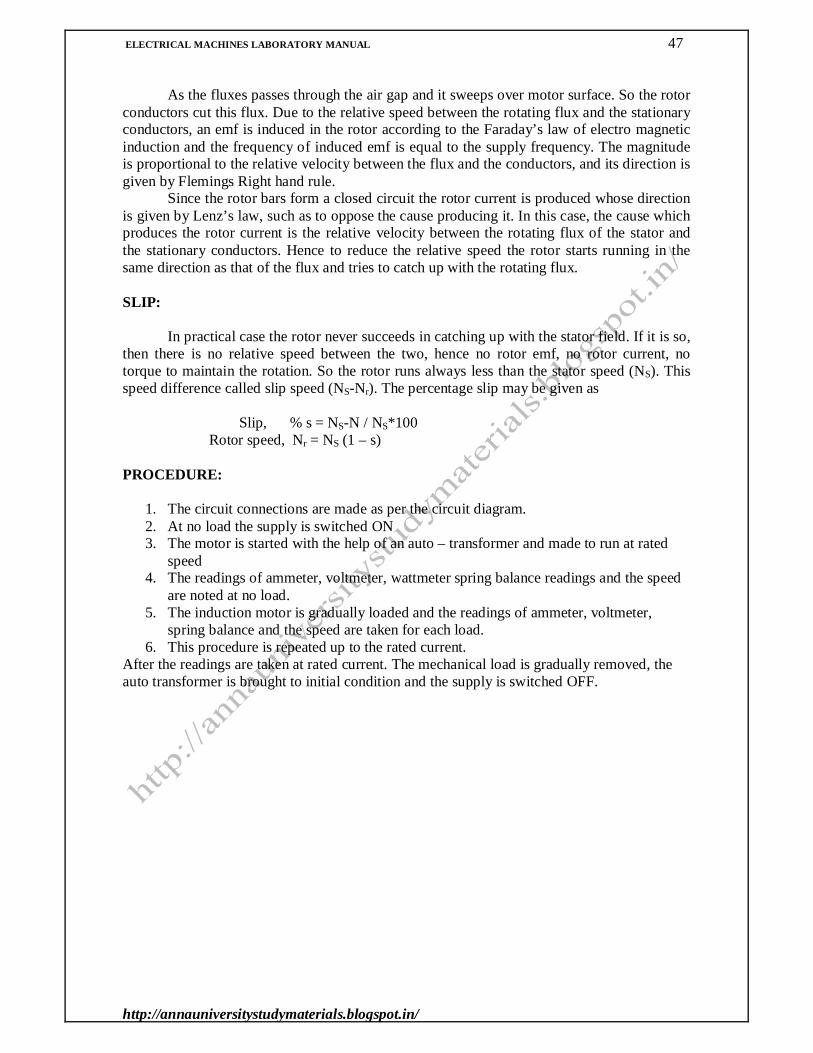
As the fluxes passes through the air gap and it sweeps over motor surface. So the rotor
conductors cut this flux. Due to the relative speed between the rotating flux and the stationary conductors, an emf is induced in the rotor according to the Faraday’s law of electro magnetic induction and the frequency of induced emf is equal to the supply frequency. The magnitude is proportional to the relative velocity between the flux and the conductors, and its direction is given by Flemings Right hand rule. Since the rotor bars form a closed circuit the rotor current is produced whose direction is given by Lenz’s law, such as to oppose the cause producing it. In this case, the cause which produces the rotor current is the relative velocity between the rotating flux of the stator and the stationary conductors. Hence to reduce the relative speed the rotor starts running in the same direction as that of the flux and tries to catch up with the rotating flux. SLIP:
In practical case the rotor never succeeds in catching up with the stator field. If it is so, then there is no relative speed between the two, hence no rotor emf, no rotor current, no torque to maintain the rotation. So the rotor runs always less than the stator speed (NS). This speed difference called slip speed (NS-Nr). The percentage slip may be given as Slip, % s = NS-N / NS*100 Rotor speed, Nr = NS (1 – s) PROCEDURE:
1. The circuit connections are made as per the circuit diagram. 2. At no load the supply is switched ON 3. The motor is started with the help of an auto – transformer and made to run at rated
speed 4. The readings of ammeter, voltmeter, wattmeter spring balance readings and the speed
are noted at no load. 5. The induction motor is gradually loaded and the readings of ammeter, voltmeter,
spring balance and the speed are taken for each load. 6. This procedure is repeated up to the rated current.
After the readings are taken at rated current. The mechanical load is gradually removed, the auto transformer is brought to initial condition and the supply is switched OFF.

ELECTRICAL MACHINES LABORATORY MANUAL 48
http://annauniversitystudymaterials.blogspot.in/
RESULT:

ELECTRICAL MACHINES LABORATORY MANUAL 49
http://annauniversitystudymaterials.blogspot.in/
CIRCUIT DIAGRAM:
LOAD TEST ON SINGLE PHASE INDUCTION MOTOR

ELECTRICAL MACHINES LABORATORY MANUAL 50
http://annauniversitystudymaterials.blogspot.in/
Ex. No: 10 Date:
LOAD TEST ON SINGLE PHASE INDUCTION MOTOR AIM:
To determine the performance characteristics of the given single-phase induction motor by direct loading. INSTRUMENTS / APPARATUS USED: Sl.no Apparatus Type Range Quantity
1 Ammeter 2 Voltmeter 3 Wattmeter 4 Auto transformer 1 φ 5 Tachometer 6 D.P.S.T. switch
FORMULAE USED:
1. Torque, T = 9.81* Reff * (S1 S2) N-m where
Reff = Effective radius of the brake drum in m S1 , S2 = spring balance readings in kg.
2. Output Power, Po = 2πNT / 60 Watts
where
N = speed of the motor in rpm
3. Input Power, Pi = wattmeter readings in Watts
4. % Efficiency = (Output power / Input power) * 100
THEORY: OPERATING PRINCIPLE:
When a single-phase A.C. supply is applied to the main winding of the 1φ induction motor, an alternating flux is produced. Due to that, the rotor tries to rotate in one direction for one half cycles and in the opposite direction for negative half cycle. This will occur 50 times within a second for 50Hz system. Therefore the rotor is standstill. Hence the single-phase induction motor is not a self-starting one. To start the single phase induction motor, a built in auxiliary winding and an external capacitor is introduced. In this method the capacitor is connected in series with the auxiliary winding. This series combination is connected in parallel with the main winding. The capacitor leads the current through the auxiliary winding (running winding). This winding

ELECTRICAL MACHINES LABORATORY MANUAL 51
http://annauniversitystudymaterials.blogspot.in/
produces another flux and this flux is positive when the main flux is negative. Due to this and the inertia of the rotor, the rotor starts to rotate in one direction continuously. OBSERVATION:
Sl.No Voltage V (Volts)
Current I (Amps)
Input Power Pi (Watts)
Speed N (rpm)
Spring balance readings(Kg)
S1 S2 S1S2
TABULATION:
Sl.No. Current I (Amps)
Torque T (N-m)
Input Power Pi (Watts)
Output Power Po (Watts)
% Efficiency
MODEL CALCULATION:

ELECTRICAL MACHINES LABORATORY MANUAL 52
http://annauniversitystudymaterials.blogspot.in/
PROCEDURE:
1. The circuit connections are made as per the circuit diagram. 1. The supply is given by closing the DPSTS. 2. The motor is started by gradually varying the auto transformer and brought to its rated
speed. 3. The voltmeter, ammeter, wattmeter, speed and spring balance readings are noted for
no load. 4. The load is increased step by step up to rated current of the motor. For various loads,
voltmeter, ammeter, wattmeter, speed and spring balance readings are noted down. 5. After the readings are taken at rated current. The mechanical load is gradually
removed, the auto transformer is brought to initial condition and the supply is switched OFF.

ELECTRICAL MACHINES LABORATORY MANUAL 53
http://annauniversitystudymaterials.blogspot.in/
MODEL GRAPH:
PERFORMANCE CHARACTERISTICS
RESULT:

ELECTRICAL MACHINES LABORATORY MANUAL 54
http://annauniversitystudymaterials.blogspot.in/

ELECTRICAL MACHINES LABORATORY MANUAL 55
http://annauniversitystudymaterials.blogspot.in/
STAR – DELTA STARTER
ELECTRICAL MACHINES LABORATORY MANUAL 56
http://annauniversitystudymaterials.blogspot.in/
Ex. No: 11
Date: STUDY OF AC MOTOR STARTERS
AIM:
To study the various types of starters used in AC motors. .
INSTRUMENTS / APPARATUS NEEDED:
1. Direct on line starter 2. Autotransformer starter 3. Star Delta starter 4. Stator Resistance starter 5. Rotor resistance starter
THEORY: METHODS OF STARTING:
The most usual methods of starting 3-phase induction motors are: 1. For squirrel-cage motors
- Direct-on -line starting - Star-delta starting - Autotransformer starting. - Stator resistance starting
2. For slip-ring motors
- Rotor resistance starting
There are two important factors to be considered in starting of induction motors: 1. The starting current drawn from the supply 2. The starting torque.
The starting current should be kept low to avoid overheating of motor and excessive
voltage drops in the supply network. The starting torque must be about 50 to 100% more than the expected load torque t ensures that the motor runs up in a reasonably short time. DIRECT-ON-LINE (DOL) STARTER:
The simplest way to start a three-phase induction motor is to connect its terminals to the line. In an induction motor, the magnitude of the induced emf in the rotor circuit is proportional to the stator field and the slip speed (the difference between synchronous and rotor speeds) of the motor, and the rotor current depends on this emf. When the motor is started, the slip speed is equal to the synchronous speed, as the rotor speed is zero (slip equal to 1), so the induced emf in the rotor is large. As a result, a very high current flows through the rotor. This is similar to a transformer with the secondary coil short circuited, which causes the primary coil to draw a high current from the mains. When an induction motor starts DOL, a very high current is drawn by the stator, on the order of 5 to 9 times the full load current. This high current can, in some motors, damage the windings; in addition, because it causes heavy line voltage drop,

ELECTRICAL MACHINES LABORATORY MANUAL 57
http://annauniversitystudymaterials.blogspot.in/
AUTO TRANSFORMER STARTER

ELECTRICAL MACHINES LABORATORY MANUAL 58
http://annauniversitystudymaterials.blogspot.in/
other appliances connected to the same line may be affected by the voltage fluctuation. To avoid such effects, several other strategies are employed for starting motors.
Induction motors can be started Direct-on-Line (DOL), which means that the rated voltage is supplied to the stator, with the rotor terminals short-circuited in a wound rotor (slip-ring) motor. For the cage rotor, the rotor bars are short circuited via two end rings. Neglecting stator impedance, the starting current in the stator windings is
I1 st = E / √ R2
2 + X22
where,
I1 st = Starting current in the motor (stator) E = Input voltage per phase to the motor (stator)
R2 = Rotor resistance in terms of stator winding X2 =Rotor reactance at standstill in terms of stator winding The input voltage per phase to the stator is equal to the induced emf per phase in the stator winding, as the stator impedance is neglected. In the formula for starting current, no load current is neglected. It may be noted that the starting current is quite high, about 4-6 times the current at full load, may be higher, depending on the rating of Induction Motor, as compared to no load current.
The starting torque is To st α I1st2 which shows that, as the starting current increases,
the starting torque also increases. This results in higher accelerating torque (minus the load torque and the torque component of the losses), with the motor reaching rated or near rated speed quickly. STAR- DELTA STARTER:
An induction motor's windings can be connected to a 3-phase AC line in two different ways: star where the windings are connected from phases of the supply to the neutral and delta where the windings are connected between phases of the supply. A delta connection results in a higher voltage to the windings than a star connection (the voltage is multiplied by 3). A star-delta starter initially connects the motor in star, which produces a lower starting current than delta, then switches to delta when the motor has reached a set speed. This type is used for the induction motor, the stator winding of which is nominally delta-connected. If the above winding is reconnected as star, (the voltage per phase supplied to each winding is reduced by 1/√3 (0. 577). This is a simple starter, which can be easily reconfigured. As the voltage per phase in delta connection is VS, the phase current in each stator winding is (VS / ZS), where ZS is the impedance of the motor per phase at standstill or start (stator impedance and rotor impedance referred to the stator, at standstill). The line current or the input current to the motor is I1 st = 3 VS / ZS which is the current, if the motor is started direct-on-line (DOL).
Now, if the stator winding is connected as star, the phase or line current drawn from supply at start (standstill) is (VS / ZS) /3 which is 1/3 = (1/3)2 of the starting current, if DOL starter is used. The voltage per phase in each stator winding is now VS /3. So, the starting current using star-delta starter is reduced by 33.3%. As for starting torque, being proportional to the square of the current in each of the stator windings in two different connections as shown earlier, is also reduced by 1/3 = (1/3)2, as the ratio of the two currents is 1/3, same as that (ratio) of the voltages applied to each winding as shown earlier. So, the starting torque is reduced by 33.3%, which is a disadvantage of the use of this starter. The

ELECTRICAL MACHINES LABORATORY MANUAL 59
http://annauniversitystudymaterials.blogspot.in/
ROTOR RESISTANCE STARTER

ELECTRICAL MACHINES LABORATORY MANUAL 60
http://annauniversitystudymaterials.blogspot.in/
load torque and the loss torque, must be lower than the starting torque, if the motor is to be started using this starter. The advantage is that, no extra component is need, thus making it simple.
AUTO-TRANSFORMER STARTER
An auto-transformer, whose output is fed to the stator and input is from the supply is used to start the Induction Motor. The input voltage of Induction Motor is x, VZ which is the output voltage of the auto-transformer, the input voltage being Vx. The output voltage/input voltage ratio is x, the value of which lies between 0.0 and 1.0 (0.0<x<1.0). Let I1 st be the starting current, when the motor is started using DOL starter, i.e applying rated input voltage. The input current of induction motor which is the output current of auto-transformer, is x I1 st, when this starter is used with input voltage as Vx. The input current of auto-transformer, which is the starting current drawn from the supply, is x2I1 st , obtained by equating input and output volt-amperes, neglecting losses and assuming nearly same power factor on both sides. As discussed earlier, the starting torque, being proportional to the square of the input current to induction motor in two cases, with and without auto-transformer (i.e. direct), is also reduced by x2 , as the ratio of the two currents is x same as that (ratio) of the voltages applied to the motor. So, the starting torque is reduced by the same ratio as that of the starting current. If the ratio is x=0.8(80%), both starting current and torque are x2 = (0.8)2 = 0.64(64%) times the values of starting current and torque with DOL starting, which is nearly 2 times the values obtained using star-delta starter.
So, the disadvantage is that starting current is increased, with the result that lower rated motor can now be started, as the current drawn from the supply is to be kept within limits, while the advantage is that the starting torque is now doubled, such that the motor can start against higher load torque. The star-delta starter can be considered equivalent to an auto-transformer starter with the ratio, x=0.577(57.7 %). If x=70 (70%), both starting current and torque are x2 = (0.7)2 = 0.49≈0.5(50%) times the values of starting current and torque with DOL starting, which is nearly 1.5 times the values obtained using star-delta starter. By varying the value of the voltage ratio x of the auto-transformer, the values of the starting current and torque can be changed. But additional cost of auto-transformer with intermittent rating is to be incurred for this purpose.
This method of starting reduces the start current by reducing the voltage at start up. It can give lower start up currents than star-delta arrangements but with an associated loss of torque. It is not as commonly utilized as other starting methods but does have the advantage that only three connection conductors are required between starter and motor.
ROTOR RESISTANCE STARTERS
If it is necessary to start a three phase induction motor on load then a wound rotor machine will normally be selected. Such a machine allows an external resistance to be connected to the rotor of the machine through slip rings and brushes. At start-up the rotor resistance is set at maximum but is reduced as speed in ceases until eventually it is reduced to zero and the machine runs as if it is a cage rotor machine.
In a slip-ring (wound rotor) induction motor, resistance can be inserted in the rotor circuit via slip rings so as to increase the starting torque. The starting current in
I2 st = Er / (R2 + Rext )2 + X2
2
where Rext = Additional resistance per phase in the rotor circuit.

ELECTRICAL MACHINES LABORATORY MANUAL 61
http://annauniversitystudymaterials.blogspot.in/
The input (stator) current is proportional to the rotor current. The starting current
(input) reduces, as resistance is inserted in the rotor circuit. But the starting torque, To = -3(I2
st)2(R2 +Rext) increases, as the total resistance in the rotor circuit is increased. Though the starting current decreases, the total resistance increases, thus resulting in increase of starting torque. If the additional resistance is used only for starting, being rated for intermittent duty, the resistance is to be decreased in steps, as the motor speed increases. Finally, the external resistance is to be completely cut out, i.e. to be made equal to zero, thus leaving the slip-rings short-circuited. Here, also the additional cost of the external resistance with intermittent rating is to be incurred, which results in decrease of starting current, along with increase of starting torque, both being advantageous. Also it may be noted that the cost of a slip-ring induction is higher than that with cage rotor, having same power rating. So, in both cases, additional cost is to be incurred to obtain the above advantages. This is only used in case higher starting torque is needed to start induction motor with high load torque. It may be observed that the starting torque increases till it reaches maximum value, as the external resistance in the rotor circuit is increased. The starting torque is equal to the maximum value, if the external resistance inserted is equal to rotor resistance. But, if the external resistance in the rotor circuit is increased further, the starting torque decreases. This is, because the starting current decreases at a faster rate, even if the total resistance in the rotor circuit is increased.
RESULT:
Ex. No: 12

ELECTRICAL MACHINES LABORATORY MANUAL 62
http://annauniversitystudymaterials.blogspot.in/
Date: STUDY OF DC MOTOR STARTERS
AIM: To study the necessity, construction and operation of DC motor starters.
APPARATUS / INSTRUMENTS USED:
Sl.NO ITEM TYPE RANGE QUANTITY 1 Three Phase
Transformer
2 Voltmeter 3 TPST Switch
ii) STUDY OF DC MOTOR STARTERS: THEORY:
Students are instructed to prepare the following topics by referring the books.
Necessity of Starter
Types of Starter
Construction & Working Principle with neat sketch
TABULATION:
Sl.No.
Type of connection
Primary line voltage in Volts
Secondary line voltage in Volts

ELECTRICAL MACHINES LABORATORY MANUAL 63
http://annauniversitystudymaterials.blogspot.in/

ELECTRICAL MACHINES LABORATORY MANUAL 64
http://annauniversitystudymaterials.blogspot.in/
VIVA QUESTIONS
DC GENERATORS
1. What is the principle of DC generator? 2. Differentiate between DC generator and motor. 3. Why the field rheostat of DC motor is kept at minimum position while starting? 4. Why the field rheostat of DC generator is kept at maximum position while starting? 5. Mention the application of separately excited DC generator. 6. Give the advantages and disadvantages of separately excited DC generators. 7. What will be the value of current in open circuit condition? 8. What is the purpose of starter? 9. List the types of DC motor starters. 10. Define voltage regulation. 11. What will you do if the shunt generator fails to build up voltage? 12. Why terminal voltage of shunt generator decreases when the load increases? 13. Why we call it shunt generator? 14. The series field winding has low resistance while the shunt field winding has high
resistance. Why? 15. On what occasions DC generators may not have residual flux? 16. Define the term critical resistance referred to DC shunt generator. 17. Define the term critical speed in DC shunt generator. 18. The efficiency of generator rises to a maximum value and then decreases. Why? 19. What do you mean by residual magnetism in DC shunt generators? 20. How does the magnetization curve change when we change the speed? 21. What factors affect the shape of the magnetization curve? 22. What information we obtain from the magnetization curve? 23. What do you mean by armature reaction? 24. What are the two unwanted effects of armature reaction? 25. DC quantities are measured by ---------------------- meters. Why? 26. How will you differentiate cumulative compound and differential compound
generators? 27. How may the number of parallel paths in an armature be increased? 28. How are the brushes connected in DC generator? 29. List the two load characteristics of DC Shunt generators. 30. What is the best way of minimizing eddy currents in the armature? 31. Define commutation. 32. What causes sparking at the brushes? 33. What is the standard direction of rotation of the DC generator and DC motor? 34. How should a generator be started? 35. What are the indications and causes of an overloaded generator? 36. Generator operates in the principle of Fleming’s __________________. 37. How do we conclude that connections between field coils and armature are correct? 38. Why series generators are not used for power generation at the power house? 39. Whether compound generators can be used as shunt and series generators? How? 40. An electrical machine can be loaded up to -------------------- % of rated current.

ELECTRICAL MACHINES LABORATORY MANUAL 65
http://annauniversitystudymaterials.blogspot.in/
DC MOTORS
1. State the principle of DC motor. 2. How may the direction of DC motor be able to be reversed? 3. Why the field rheostat of DC motor is kept at minimum position while starting? 4. What will happen if both the field current and armature current are reversed? 5. What will happen if the field of the DC motor is opened? 6. What will happen if the direction of the current at the terminals of a series motor is
reversed? 7. What happens when the DC motor is connected to an AC supply? 8. What will happen if the shunt motor is directly connected across the supply line? 9. Mention the applications of DC compound motor. 10. What is the function of interpoles? 11. How the interpoles are connected? 12. How the interpole windings are connected? 13. A DC motor fails to start when switched on. What could be the reasons and remedies? 14. A DC motor is found to stop running after a short period of time. What do you think
could be the reasons? How do you remedy each? 15. When does the armature of dc motor likely to get over-heated? 16. What are the applications of DC series motors? 17. What are the special features of a DC series motors? 18. Which type of starter is used for DC series motors? 19. How will you control the speed of DC series motor? 20. What will happen to the speed of series motor when the supply voltage is reduced? 21. What is the importance of the no load current of the motor? 22. What will be the efficiency of the motor at no load? 23. Which one of the speed will be higher either no-load speed or full load speed? 24. How will you control the speed of DC shunt motor? 25. Which type starter is used to start the shunt motor? 26. Why we use starters to start DC motors? 27. Where we use shunt motor? 28. The differentially compounded motor has a tendency to start in the opposite direction,
why? 29. What are the advantages of a compound motor? 30. What are the other names of Hopkinson’s test? 31. What are the advantages of Hopkinson’s test? 32. State the advantage of Swinburne’s test. 33. Is it possible to conduct Swinburne’s test on DC series motor? Justify. 34. State the Torque equation of DC motor. 35. DC series motors should never be started on no-load. Why? 36. Differentiate between cumulative compound and differential compound motors. 37. What is the function of no-voltage release (NVR) coil provided in a DC motor starter? 38. How does a 4-point starter differ from 3-point starter? 39. Why is field control method superior to armature control method for DC shunt
motors? 40. Name different methods of electrical braking of DC motors. 41. What is meant by speed losses in DC machines? 42. At what load does the efficiency is maximum in DC shunt machines? 43. Why is brake test not suitable for large size machines? 44. What are the advantages of Hopkinson’s test over Swinburne’s test and what are its
limitations? 45. Explain the operating principle of DC motor starter.

ELECTRICAL MACHINES LABORATORY MANUAL 66
http://annauniversitystudymaterials.blogspot.in/
46. Why the field control method is employed only above the rated speed in DC shunt motors?
47. Why the armature control method is employed only below the rated speed in DC shunt motors?
48. Why the DC series motors have high starting torque? 49. Why the motors are rated in HP? 50. What will be the approximate value of armature and field resistance of DC motors? 51. What type of starter is used for DC series motor? 52. What is the importance of no-load current of the motor? 53. What will be the efficiency of the motor at no-load? 54. Which one of the speed will be higher either no-load or full-load speed?
TRANSFORMERS
1. What is the function of a transformer? 2. What is a load? 3. Mention the types of transformer. 4. Explain the operating principle of a transformer. 5. List out general applications of transformer. 6. What are core type transformers? 7. What are shell type transformers? 8. Distinguish between power and distribution transformer. 9. What is the need of stepped core in transformers? 10. Define voltage regulation of a transformer. 11. At what power factor the voltage regulation of transformer is maximum? 12. Under what value of power factor a transformer gives zero voltage regulation? 13. Why do we perform load test when the efficiency can be determined by O.C. and S.C.
tests? 14. What transformers are rated in kVA? 15. How the eddy current loss can be reduced? 16. Can you reduce the hysteresis loss by making the core laminated? If not how? 17. Does the transformer draw any current when its secondary is open? Why? 18. Define power factor. 19. Define frequency. 20. What will happen if a transformer is connected across a DC supply? 21. Is copper loss affected by power factor? 22. How does the change in frequency affect the operation of a given transformer? 23. The main purpose of using core in a transformer is to ----------------------. 24. A step-up transformer increases ---------------------. 25. In relation to a transformer, what does the ratio 20:1 mean? 26. When the efficiency of transformer is maximum? 27. What is an auto transformer? 28. Distinguish between auto transformer and ordinary transformer. 29. Define all-day efficiency. 30. What are the components of magnetic losses in transformer and on what factors do
they depend? 31. How are various losses in transformer classified into constant and variable losses? 32. What test is to be conducted on a transformer to estimate its voltage regulation? 33. Why the S.C. test is performed on HV side? 34. Why the O.C. test is performed on LV side? 35. State the advantages and disadvantages of Sumpner’s test.

ELECTRICAL MACHINES LABORATORY MANUAL 67
http://annauniversitystudymaterials.blogspot.in/
REGULATION OF ALTERNATOR BY EMF AND MMF METHODS
1. What are the advantages of rotating field in alternators?
2. Why are alternators rated in kVA and not in kW?
3. What is meant by armature reaction in alternators?
4. What do you mean by synchronous reactance?
5. What is synchronous impedance?
6. Define the term voltage regulation of alternator.
7. Why the synchronous impedance method of estimating voltage regulation is considered as pessimistic method?
8. Why the MMF method of estimating the voltage regulation is considered as the optimization method?
9. What do you mean by residual EMF in an generator.
10. What are assumptions made in the EMF method?
11. What is the advantage and disadvantage of EMF method?
12. What is the advantage and disadvantage of MMF method?
LOAD TEST ON THREE PHASE INDUCTION MOTOR
1. Why an induction motor is called rotating transformer?
2. Why an induction motor will never run at its synchronous speed?
3. State the difference between slip ring rotor and cage rotor of an induction motor?
4. What is cogging of an induction motor?
5. Give the conditions for maximum torque for 3-phase induction motor?
6. What is the advantage of wound rotor motor over a squirrel cage induction motor?
7. What are the advantages of 3-phase induction motor?
8. What is meant by crawling of induction motor?
9. How does the slip vary with the load?
10. What are the possible reasons if a 3ф motor fails to start?

ELECTRICAL MACHINES LABORATORY MANUAL 68
http://annauniversitystudymaterials.blogspot.in/
LOAD TEST ON SINGLE PHASE INDUCTION MOTOR
1. Why the single phase Induction motor is not self starting one?
2. Explain double revolving field theory applied to a single phase induction motor.
3. Mention any two starting arrangements used in the case of a single phase induction
motor.
4. What is the purpose of the auxiliary winding in a single phase induction motor?
5. What is the function of centrifugal switch in the case of a single phase induction
motor?
6. How the direction of rotation of a single phase induction motor is reversed?
7. Can the Shaded Pole Induction Motor can be reversed. How?
Why single phase Induction Motor has low power factor
STUDY OF AC MOTOR STARERS
1. What are types of starters used in squirrel-cage motors? 2. What are types of starters used in slip-ring motors?
3. State the effect of rotor resistance on starting torque