electrical measurements and their ... - rsp-italy.it
TRANSCRIPT

~ PEBIMENTEB ~ VOLUME XXV No. 10 MARCH 1951 ~~ ________ ~C~'~'~':';!':h'~'~':"~'~'~"::":':"~'~'~':d:"~c~.:m~ .. :"",~.;c.:;m~~:':d! •• ".~M:':':':"~U:.~'~.~'~ .• • .......... ~
V> :z: o I-
"" c.:>
-' .... .... "" -'
"" '" l-V>
= o z:
'" ... :z: I-
o :z:
"" V> Iz: ... ::E ... '" = V>
"" ... ::E
-'
"" c.:>
INTERMODULATION DISTORTION
• N ON·ll N EAR 015TO R TIO N :l.lTccts the reproduction of nn acoustic signal by introducing components that. are not present. in the orig;inuL The effect of these cxlmllcous cornj:)ot1<'nts is one of unlloynncc to the listener, first, bCCHUSC they cun interrere with, or mask, the clt'sired signal, and, second, because the)' can nutkc the reproduced signal sound unpiCIl...."l.lnt to the listener.
Both these effccts £I.I'C subjective. They nrc measurnblc only by l)Sychological t.cdmiqucs and not by an," cxi"tillg objccti,'c tests with ph,ysical instmmcnts. tiuch factors n.;; annOyance, nllLSking, and loudness fire evaluated statistit:l.lly from the results of it large number of tests on many listeners to givc an !l.verage subjcctive impression of "nOl'IllUJ" IistellCrs. Much work hilS been donu ill tbis fie ld, particularly by the Psycho-Acoustic Laboratory at H:trvard Uni\'cl"SiLy, the BeH Tclephone Lilboralol'ies, !lOllle government laboratories, and numerous othcr university laboratories both here and abroad. ;\ Iuch rell1llins to be done, particularly on the factor of annoyallce, which is alTC('ted SO mllch by past influences, by what one is trying to do Itt the moment,
We Gre finding il IncreGll ngly difficult withoul exte nding DO ralingl to oblain Ihe raW malerlall and precision companenl. which are required far Ihe manufacture af General Radia equipment .
In additian, l a many priar;ly-ra,ed arden a re being received that the delivery of materiGI againl t unraled atders il becoming Increa l ingly uncertain. We are I t ill accepling unrated Orde' l and are doing our ulmost to fill them, but II become. mOI"9 difficult ellery day.
The Roting 00_98 con be obtained for the procurement of euentlat equipment by addrening ° requeslto you. Contracling Officer if you are ° prime controctor of a mililory department. If you are a l ubcontroctor, the requei lihouid be addreued 10 Ihe prime conlroctor, who will in turn gel in touch with the military department concerned.
We urgently reqUelt, therefore, that, to inlure against unrea l onable d eloy ond to anist us in replocing invenlory, you do everything pouible to obtain and 10 extend to UI priority on any of your unroled orders which we moy now have or on any new orders which you will be placing with us.
IET LABS, Inc in the GenRad tradition
534 Main Street, Westbury, NY 11590 www.ietlabs.com
TEL: (516) 334-5959 • (800) 899-8438 • FAX: (516) 334-5988

GENERAL RADIO E XI' ERI M E N JER
nnd by the time 8{'fJuencc of cvents. I n :lddition, there is the task of devising fI:l libfnctol'Y pllysicfl.l tests fol' sOtilldI"t'pmdllcing equipment to c"ruUtlt{' facIal'S thaL can be correlated with the results of the psychological tests. Some of th~ possible ph'y8ical tests arc consiuercc.i here.
For mfiny yeal'S th{' main test for nonlinear distortion has bccn the harmonic distortion test, which e"aluutes the hnrmonic \'ompOllentii generated by nonlinear amplification and rt'prociuction of the applied signnl . It hag long ~n recognized, however, that some systems lI'ith very low harmonic distortion still do !lot souud "right" to the hearer.
I.k'Ciluse of this inadequacy of the harmonic distortion It'8t , intermodulation tl';;ts 11I\\"c bct'n d\'\'elopcd. The first of these me8surcs til(' modulation of a high(rC"queney tone by I~ low-frequency one, II mcthod that gives sali.sfactor'y results on somo systems and has been udopt ('d by the Society of Motion Picture and Tel('\"isiou Engineel's (S)' I PTE).
E"eu lhis lesl is in:ldequa.te for some J,lmpose!, as will be shown later in thi:'! articIt', und tl third method which
,
measures the difTcl'encc tones produced by the illl.ermodulation of two highfrequency tones has been developed. For a single tl'St. method, this iIPI-'CIU'8 to be tbe most satisfactory.
The acceptabi lity of tbis test, whieh is reconuncudcd by the rntel11ationai Telephonic Consultati ve Committee (CCI F), is shown by a series of distortion tests rcccnt ly madc on a hearing aid. T hese tests al'c discussed ill tenus of rating lhe hearing nid, nnd they !u'e also used to illustmtc ~ible effects that cun cause trouble in olher sound I'eproducing systems.
Th is hearing aid, a bigh-q uality one and of excellent lI'ol'km:l.Ilship, was obtai ned through the courtesy of the l-Iur\'/\rel University Psycho-Acoust ic L.'lbomtory, where qUlllity rutings by subjccti"e test had been made on it. It has Il tone control 111:lt permits two settings, find the test panrl mted the qUlI.lity as markedly poorer with t he tone control in lhe A position t hlill in tbe /J position. This i" lhe rc\'erSl' of what might he e,xpeeted from thc f ft'CjUCIICy r('SI>OIlSC characteristics for the two positions, which show tI I)('uer high-frCfluenry rc-
INPUT LEVEL- 70 db BELOW l'oQLl
.§ 120 II II
\\ / TONE: (.()NT ROL
• N
§ 0
• • • , " ~ " ~ ~ ~ • c
~
FUNDAMENTAL
'00
/'
80 V'" HARMONIC ~NTS
60
'0 <Xl
,. ,
1/ /
, , / TONE 00NfA()t.
8
I I I I
A
\' V '( "-V \
f\ 8
n! !'\ 1
;~\ . " j \
" " " ,'" (~' ''': A
A
'-r\ .1 J\ ""'" FREOUENCY OF FUNOAMENTAL IN CYClES P£R SECOND
Fig"" . I. Sound·p, ...... ,. 1 ..... 1 p rod"".d by th .o,phone o. 0 function of f,.q .... ncy fo, the two po.ition. of the ton. COn· trol . f undomentol ond harmonic componenll 0'" plotted ot th. r ... ".jom.n. tal frequency.
IET LABS, Inc in the GenRad tradition
534 Main Street, Westbury, NY 11590 www.ietlabs.com
TEL: (516) 334-5959 • (800) 899-8438 • FAX: (516) 334-5988

, Bponsc for the A position. These curves show the mal'ked resonances thut. arc typical of heMing l1ids (sec Figure 1).
TEST CONDITIONS The hearing aid was tested fOl' llon·
lincar dist.ortion by supplying an eleclrical input at the microphone lerminaJs from a Geneml Hadia TYI'E 1303-:\ Twl?Signnl Audio Generator'.
The earphone of the hcnring aid unit. was ('onncctcd to an approxinlt~te equivalent of the standard 2-c.('. coupier1
,
using 1.111 .\Itee Lansing 2113 Microphone as the trnnsduccr. The output of the microphone was analyzed by t\.
General Hadia TYI'~; i36-A Wnvc AnalyzN. rn ench figure, the levels I'<hown nre sound-pressure levels in the 2-(".c. eouplN, and the operating level was selected 10 correspond approxinmtcly to that. for which the quality ratings were made,
HARMONIC DISTORTION
The harmonic clistortion results of ~l', G. r.t~reon, "AnAu(Ii,..~ucnfr Si~] Ge .... 1M"r for Xo,,·I,;...,.,. DI&I ..... I.J\>n T •• n .• : (;"""",1 RaJ." EIpn"" .... I .... , A,,,,""I, 19.-.0.
tASA 1..l!~G-1O~9, "Amm ... " Stan<bnl :\Iethod fur tbe Coupler Cahbnoti"n of !i:l.rpbo ..... ••
MARCH , 19S1
Figurc 1 show the typical ]~onancc
]lcllks normally found in these 1'Il(l:lSlll'l'mellt~. The.y do show lh1ll the distorlion in the B pO!'ition is lower than in the It position , which is in the right direction. 1I 0IVe\'(~r, in the region above 700 cycl<'8, where there is fI. difTerence, lhe distOI'lion component.,; [11'(', in either case, 40 to 50 db down from the funda..mentaL They arc therefore n.lmOSL completely masked by lhe funcin.llwlllal. For ('it hel' position of lhe tOile control, tl.4' distortion is in the range of what 18
normally cOllsidered good quality.
INTERMODULATI ON SMPTE METHOD
The re.<\uhs of somc mcasur('meniil by the second method arc showll in Figure 2 as a function of frequeucy. A highfre<luency signal and H lower-frequency sigllnl weI'(' .-.i nmltaneollsly applied at the input. The output Icvels of these signals fire shown for referellce. In one case :l signal of 1 kc Willi uS(.'<i tiS the high-frf'Qucnf1Y signul, and ill anothcr lhe high-frequcncy sigll!).l wus ike. In gcncral the dislortion componcnts fire 40 to 50 db below the Ic\'e1 of ihc uesircd
EOUIVALENT INPUT Lf VEL -70db BELOW II,QLT
" o
gao flou'. 2. Sovnd·pr ... Ufe ~ level of inlermod"lolion I/J
dl.torlian compon."" o. 0::
d. t.rml .. ed by ,lie SMPTE ~ 6 .... tIIod. Eod! co",p."..nt I/J
;, plotted 01 II. own [ frequency. Upper (\/Of ••
lhow th. lev.1 of .... am' ~ plifled input "9nol.. g 4
0
0
4 '1 AMPL ITUDE RATIO
TONE' b,N~~OL
I- LOW·FRECUENCY ~ I '~HlGH-FREOOENGV SIGN
SIGN~~ , ,
/ OISTORTION COMPONENTS
• - I~~ - -1'- \ ~ ,
i 1 00 1.000
FREOU(NC'I' IN CYCLES PER S£CQHO
•
~
IET LABS, Inc in the GenRad tradition
534 Main Street, Westbury, NY 11590 www.ietlabs.com
TEL: (516) 334-5959 • (800) 899-8438 • FAX: (516) 334-5988
0
N
~ 100 , • • I
~ B 0
0
GENERAL RAOIO EX P ERI M EN TER
sign sir<, SO far down that they are completely masked by the desired signals. Here again we have no satisfactory indication of sel·ious distortion.
I N TE R MODULATION CCI F METHOD
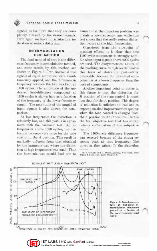
The final method of tcst is the differ. cncl'-frequency intermodulation method, and some results by this method are shown ill Figure 3. Two sinusoidal test signals of equal amplitude were simuliancously applied, and the difference in frequency between the two was kept at 1100 cycles. The amplitude of the un· desired first-difTerenee component at 1100 cycles is shown here as a function of the frequency of the lower-frequency signal. The amplitude of the amplified input signals is also shown for comparison.
At low frequencies the distortion is relatively low, and this part is in agreement with the harmonic test. But at frequencies above 1500 cycles, the distortion becomes very large for the tOile control in the A position. This result is markedly different from that obtained by the Imnnonic test where the distortion at high frequencies was smaU. Thus the harmonic test would lead one to
• assume that the distortion problem was mainly a low-frequency one, while th is test shows that the rctdly scrious distor· tioo occurs at. the high frequencies.
Considered from the viewpoint of masking effects, it is clear that this I lOO-eycle component is strongly aud ible when input signnls above 2000 cycles are used. The dissymmetriclli nature of the masking curve nt high levels' makes this form of distortion particularly noticeablc, because the unwanted component is at a lower frequency than the dcsiJ'ed componcnts.
Another important, point to notice in this figure is that the distortion for B position of the tone control is much less than for the Jt position. This degree of reduction is sufficient to lead olle to expect a marked improvement. in quality when the tone control is changed from the A position to the B position. Here is the first objective test that has showu definite confi rmntion of the subjective result.
The llQO..cycie difference frequency was selected becausc of the strong response peak at that frequency. The question then arises: Is the distortion
'S. S. St('vell!! "n.d IJ. n.. ..... lltori"fl, New Y()tk, Jobn Wi~y & 80111, t"o., 1938, Chapter 8.
EQUIVALENT INPUT LEVEL - 70db BEl O'N j '.QLT
~MPL1FIEO INPLIT \"-SIGNALS ~ "-V
./ ""V"
-f- ~ "" AMPLITUQ£ OF QIFFERENCE FREOUENcY (1IO()c)COMPONENT
I II
lONE CONTR OL , ) P
/i f\ , i'-'
II \ B
r---
B ,
I
Figura 3. Sound.preuura la ve t of /In'.ordar In· 'e'mod"lolion component plalta d a, a function of Ika !awar·f,aquenty inpul ,ignol.
00 1.000 O{X1J FREOUENCY IN CYClES PER SECOND Of' LOWER F~Y SIGNAl
IET LABS, Inc in the GenRad tradition
534 Main Street, Westbury, NY 11590 www.ietlabs.com
TEL: (516) 334-5959 • (800) 899-8438 • FAX: (516) 334-5988

• for other values of difference frequency also large? Result.s for othe!· values are shown in l?igure 4. The lIDO-cycle results are reproduced here, and in addition there are distort ion characteristics fo r difference frequencies of 900 cycles, 1500 cycles, and 2850 cycles. The 2850-cycle value is also at a response peak, but the other two values nrc away from the peaks of response. AJI show the same general tendency of a gradual rise to lugh values of distortion at. the higher frequencies, but the distortion components in tbe vici nity of peaks of response are the most important.
The results as a function of level for 0.
particular pair of input signals are shown in Figure 5. At the left is the analyzed sound pressure for the tone control in the A position and on the right, for the B position. The levels of the desired signals at 3000 and 4100 cycles are shown by lhe solid lines. and the levels for the distortion components are shown by dashed lines. In both cases the level of t he higheNlrder difference terms at 1900 and 5200 cycles are smull compared to the level of the first difference of 1100 cycles. At the assumed opera.ting input level of 70 db below I volt , the I IOO-cycle distortion com-
MA.RCH , 19 5 1
ponent for the it position is only 4 db lower ill level than the stronger of the two desi red components. rn the B position the level of distortion has dropped to 28 db below the strong 3000-cycle signal. This Z4 db improvement. certainly would be expected to show up in It subjective test, as II. marked improvement. in quality. which is in agreement with t.he subject test.
T he results shown have been obtained ou only one heari ng uni t, and, consequently, no final conclusions can be drawn. But these results are probably typical because of the usual over-all reduced power hanilling capacit.y of heariog-nid units at high frequenc ies, and because of the marked response peaks occurring in most hearing aids. Therefore, it is highly probable that t be diiTerence- frequency intermoduln.tion lcst is gcncmlly the most significant non-linear distortion test for heari ng:lid units.
The foregoing results should oat be interpreted M indicat iog that heari ng aids a rc low-quality devices. Both t he performance requi rements and the design limitation of a device to compensai.e for heRring loss differ considerably from those of a system to reproduce sound in
EQUIVALENT INPUT LEVEL - 10 db BELOIV I VOLT
TONE CO NTROL - A '\ "" 00,
Flour. 4. fi"I>Ofder in 'e r· modulOliQft di. tortlon for four "olues of difference frequency.
, " " , ~ 80 • "
~ '0
~
I I I I I e AMPLIFIED INPUT "- ) \ SIGNALS I'
V -7 ~ • , \
/' / f' 1' 28SOe /{
,.. 1- .L' t;.f ·I!lOOc
"I'i' '-.0 1'9000
AMF'LlTUDEI
OF DI FFERENCE
'TTl '[' i TIT'" ~ ' 0
00 1.000 ()fXJJ FREOUENCY IN CYCLES PER SECOND OF l.OW(R FREOl£hI:;'" $IGW.L
IET LABS, Inc in the GenRad tradition
534 Main Street, Westbury, NY 11590 www.ietlabs.com
TEL: (516) 334-5959 • (800) 899-8438 • FAX: (516) 334-5988

~
GfNU: Al RA DIO eX PERIME NT ER
It communieai ion system, Small size and light. weight are c."&'lltiul , and tlle nmplifiel' S('(>ms unhclievably small to the engineer accustomed to working with audio power amplifiers, The desirable fn.'queoI'Y reBPonsc characteristic is detcrmint'(l hy hubjcctivc tests which! for this product. arc the ultimate proof of I'onsumcr ueeeptubilit y,
The mellSurcments OIl the hearing nid \\'ere made ~tluse of the available ps)'C'hologiclll data aod becal1se the electrical setup was ~imple. This type of illvestigation should be extended , and \\'e should like 10 encourage those who arc interest(.'<i and capable of doing 50 to pursue the pl'Oblem for other communi('ation elemcnts. [n order to encourage this further ilH'esligation , 8. fel\' pos~ibilities are diS("usscd below, hut it should be Iloted that adcqunt.c cX I>erimcntal proof of these pos"ibiJitie5 if! not yet. available.
OTHER AUDIO SYSTEMS Effects which arc simi lnr to those
shown here for heuring aids occur in IUldio am plifiers, radio receivers, public
• address systems, tl nd othel' ek-etmlleoustic devices. Oue of these is thl' e!Tect of resonant peaks of rcsponse, T hese pcnks of response can exaggcrulc components pl'oouced by distortion to a serious c1egrro, lior exam ple, most loudspeakers used on mdio receivers do not have a smooth and ullifol'm respollJ'.C characteristic as a fUll ction of frequency. The poor characterislic is m:l.inly a rCl3ult of tbe gre:l.t difficulty, and COIl
sequently grellt expense, of obtaining :l better ehamcleristic. I n addition! somc IOllci-spe..'lkcrs arc intentionally made to have markedly higher response in the moderately low-frequency rnnp:e, This hump in the chamctel'islic gives:l typitn l boomiucss that. is desired by somc, but. that. <llIickly becomes annoying to others, With this type of response from a rcprod ucer, one hears a boomillCSl! associated with speech !lnd most music, even when theJ'e obviously are no st rong low-fre<luency tOIlCS present in the Migi nnl. It is c.'\sy to sec that Uu~se components cftn be producl."(1 by nOll-linen!' distortion. T he intcrmodlll!llion of two higher-frequency tones produces t Ile
Figur • .5. In! •• modulcuion diotOrTion 0.0 'unction of ;"pul 1.~.L The opuol;"glev.1 lot 1tI .... bj<td; .... I •• " (or. •• pond. 10 on input 1 ..... 1 of opproK' ... ol.ly 70 db belo .... 1 yoll.
INPUT SIGN4LS _ 'OOO~ e. 4100~ 'SOLIO LINES) III M1PLlfUDE RATIO (C(;IF METHOO)
DISTORTION COMPONENTS - 1I0Dc, 1900c . !l200e iD4SHED LINES)
l'ONE CONTROL - A -~ V /
"00<
1/ " TONE: ca.rTROL - B
.~
0
j' ~ .. -, /
Vt ,"" / ~
/" '''' • • , g "
100
• 0
/ .~
> I
I
/ // // ' ~ / / , / ,
, 1/ "
Y I
-~ f--- --//
/ I ,-<>-0
/ Y '<-T~ ,
n .. ?
,
",,'00 oiL' -• 0
I 1,( , '~ o / I " •
" 00 " 00 '" EQUIVALENT INPIJ1' r.E'lltl. - db !lELOW I VOl.. T
IET LABS, Inc in the GenRad tradition
534 Main Street, Westbury, NY 11590 www.ietlabs.com
TEL: (516) 334-5959 • (800) 899-8438 • FAX: (516) 334-5988

, IOIVCI'-frt-qucncy tOile as !\ difference fn .... qucllCy. Then because of the CXllggurat cd response a t ~hc loll' f requcllcies tJ lis tone c3n become relatively strong wi lh the associated effects described above. [n Illcusuring the magnitude of this distortion, it is I1CCessl\ry to include the loud-speaker in t he mC:lStlrcrncnt.s, tl lltl ::In excellent microphone is requi red as 1l
pickup .. \ £ter determining un over-lI l1 respollSC cha.racteristic, the eel Li' test call be made as a fllDct ion of frequency with the difference frC<lucncy set lo the various maxima in Lhe l'CSponsc chllrtlctcristic.
T he extensi \'c usc of pl'e-emphasis of high frequencies in present-day COIll
mu nication systems has increased the power hllndling requi rements at high frequencies. The Cel l" test is the best. for determining the effect. of the PI'Cemphasis. U intermodulation {)Cem'S ruter pre-ern phas i ~ to produce a lowerf rcclucncy d iffereJlce lone, lhen t his component. bt..'Comes m OI'e im l>or lant. after de-emphasis, since the higherfrequency desired coml>onents a.re rcducC(1 more in levcl thau t he undesired low-frequency component . T he usunl recordi ng systems of todl\.Y use Pl'(}clllpha.~i8 of the high frcqucncies. But most. of t hem arc forlU lilltcly armllge<.l to be essentially symmetrical in action so that IInder normfil conditiolls \rcry ii i tic of this first difference eoml>onent is produced. For example, t he symmet rical nalure of the magnetization chamcterislic of magnetic tape is one of t he important factors in its success. However, if lln unbalance occurs in tbe magnctization, eitber becausc of dissymmelricnl binsing or residual d-c eOOl I>onents, distortion cau occur 10 prod uce a fi rsLdifferellce frequency component of 11
magnitude depending on the extent of the dissymmetry. T his CCLF lest. for t.he
MARCH . 1951
first difference elm be a. sensitive check on proper biasing, tl nd t he tt,'st fOl' t he second difference C~lIl be useu to show liP additionttl di"turtiou'.
A few md io manufacturer!! l\tIvc aLtempted to compcll5:1tc for 1)Qu1' highfrC<luency retiponJ:!{' in loud-speakers by boosting or Ilrc-cm phasizing the higb fl'Cquencics. This p rocess is intended ml
II step towllI'd high fidelil,y and increused brill iauce of reproduci ion . Il owever, t he incrcllSCd power handling ability tbai this requires at high frequencies i" frequently 001. provided. The result is incrca.'lcd distl)l·liort. The dlllrll.eleristic drop ill OUtput ai high frequencies in t be loud-speaker then reduces tbc level of ! he high-frequency signals comptlred to any lower-frequcncy intcrml){iu lation componcnt!!. The usual result is that the radio rcpl'Oduetion sounds beLter whell the cont rols are 8(Ji at tl. normal position rn.thCl· limn at th is so-culhxi Itbigh-fidclity" I>osition. T be proper method of <'hocking fo r this type of t rouble is by lhe eCI F test with the loud-speaker included as:l part of lhe system.
Because of nOll-Linearity ill the loudspeaker stl8]>cnsioll IUl d cOile materiul, 8ubhannonics can be gcncmt.l..'Cl in many l oud.speakf'~."'· T hese oceur :It a number of dis tinct. frequencics, nnd the subharmonie may be some r('lnti\'e!y complicated fraction, for example, 5 ]3, of the exciting frequency. When flU attempt is madc to excite subhnnnoujcs directly, :l high power level mus!. be used, and the subharmonics build up t!lther slowly. Beca.use of Lhia slow
' r,. c. n ollnt<'. " Technlq""" J(If I II'IJ)I(> ..... 1 :'o1"lIn<-1.i<l 1leoo,)c.h ~I[:· KIt!tltVn1 S/tqi"""";"4I. Vnl. G!o, NQ 10. <ktolw:r, li)~9. 1>1'. 83tl-S4I .
I II. J.'. OIM". Hr ..... "'/.f '" _~ «)"MictJ H~qi" .. Ti"il. N~w YC>tI<, O. v." NOItrBlIo.l. Second .. "lit;"", I{tH. I>p . 107'"
"II. II. lid! . nll i l . C H~rt\~ "-'I""'ur~'RI'DtJ fur AWin. in !.he E .... rUllltion 01 IhoI u~l,t)' of 1.ou"'I""'k~rl." \ btt raet. J . .I...,..., Sox Am. 01. ZO, So t . July, I!H8,
1111. 006f.
IET LABS, Inc in the GenRad tradition
534 Main Street, Westbury, NY 11590 www.ietlabs.com
TEL: (516) 334-5959 • (800) 899-8438 • FAX: (516) 334-5988

GENERAL RADIO E X PERI M E N TER
build-up, it has been suggested that, these subhllrmonies Cannot become a sign ificant, factor in the reproduction of music and SI>ccch. However, becuuse these signals a re complex, other factors may enler to make occasional generation of subhannonics possible of sufficient, magnitude to become annoying. One tone appcuring in a signnl may be at a frcqucncy for which subharmonics can occur and it may have associated with it a tone different, in frequency from the first by a value approximately equal to the subharmonic. Then nOll-linear distortion in the driving amplifier may generate enough of this difference frequency to aid ill subharmonic generat.ion at a level much lower thun normal. In addition it can produce an initial signal
• to cause build-up of the subharmonic to It sit.'llificant level in 8. much shorter time than is otherwise possible.
EQUIPMENT
In general an investigation of elTeets of the type described requires a versatile signal source. Not only are two tones required for the intermooulatioll tests, but also each tone must be adj ustable in frequency over a wide frequency range. The General Radio TYPE 1303-A Signal Generator' provides tbis versatile signal source, and the General Radio TYPE 736-A Wave Analyzer is 8. suitable, highly selective voltmeter to use us a detector for determining the extent of the llon·lincar distortion.
- A. P. G. P ETERSON 'I __ en
TilE Ceneral iladio EXPI-: ,UMf:IVTf:n is "w iled t(l it/lOut. clwrgc each
month to eltg illCers, scientists. t.ech lli.cia lu . a"d otllers in ' erested
in c01lununication·frequ.en cy IHCtISUrem ent and conl.rol proble n Ui.
When sending requests for subscrilll.ion s (HId nr/drcss-clwngc IW I.ices,
plcusc su.pply tlte fo llowing jlljor llwt.ion : /tume. CO"'fJfIfl.y tuldress. I.y p e
oj business COtnlJtlllY is ellgaged i'I, (Hut t.itle or IJOsit.ion oj intlividuili .
GENE RAL RAD I O COMPANY 215 MASSACHUSETTS AVE NUE
CAMBRIOGE 39 MASSACHUSETTS TE LEPHONE : TR owbddl1 S·UOO
BR ANC H EN GINE ERIN G OF F I CES ~EW 'ORK I, N[W YORK
II WEn STH£t tU .-WOrl ~ ) · 5111
lOS ANG£lES II. CUHOAIIiA Itil MO RTH SE WARD nREn
TEl. _ II0 1l ' ..... '·111 1
, " ICAOO ~, ILLINOIS IH SO UTII MltillGAN AHMUE
TH . WUII. J·nn
IET LABS, Inc in the GenRad tradition
534 Main Street, Westbury, NY 11590 www.ietlabs.com
TEL: (516) 334-5959 • (800) 899-8438 • FAX: (516) 334-5988