electrical motors wiring s. christian mariger ph.d. biological systems engineering virginia tech
TRANSCRIPT
Electrical Motors Wiring
S. Christian Mariger Ph.D.
Biological Systems Engineering
Virginia Tech

Examples using Ohm’s Law
• Determine the resistance of a soldering iron that draws 9.5 amps. The iron is plugged into a 120v outlet.
• Volts = amps x resistance or E = IR
• R = E/I = 115volts / 9.5 amps = 12.1 Ohms

Examples using Ohm’s Law
• Determine the resistance of a 100 Watt light bulb on a 120 volt AC circuit.
• Watts = volts x amps

Examples using Ohm’s Law
• Determine the resistance of a 100 Watt light bulb on a 120 volt AC circuit.
• Watts = volts x amps
• Watts / volts = amps = 100/120 = 0.83

Examples using Ohm’s Law
• Determine the resistance of a 100 Watt light bulb on a 120 volt AC circuit.
• Watts = volts x amps
• Watts / volts = amps = 100/120 = 0.83
• Resistance (Ohms) = volts/amps
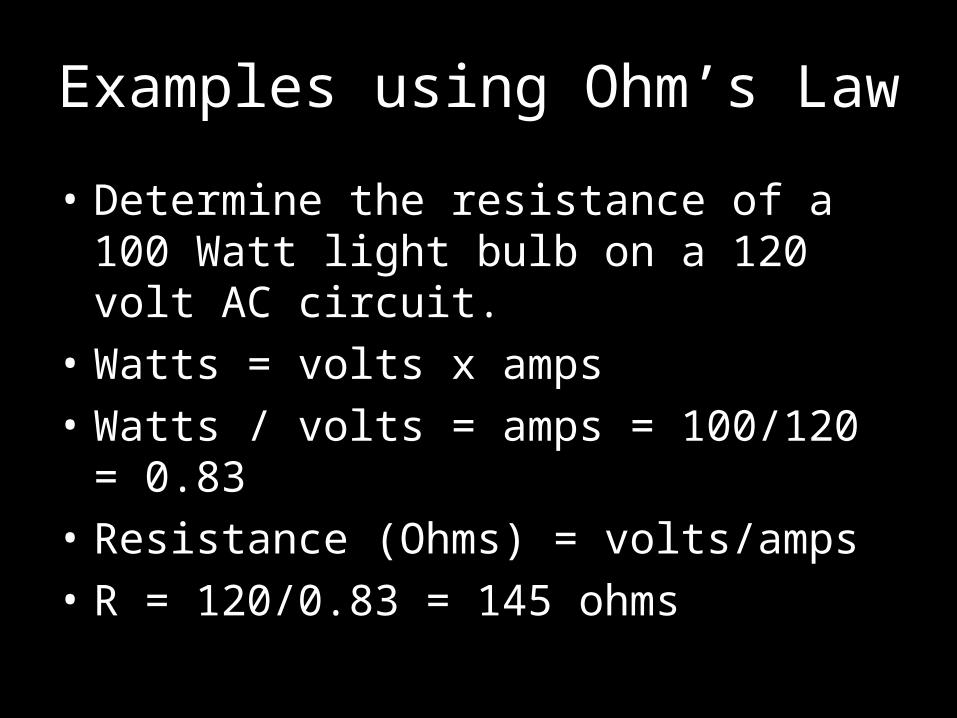
Examples using Ohm’s Law
• Determine the resistance of a 100 Watt light bulb on a 120 volt AC circuit.
• Watts = volts x amps
• Watts / volts = amps = 100/120 = 0.83
• Resistance (Ohms) = volts/amps
• R = 120/0.83 = 145 ohms

Electrical Generation & Delivery
• Most electricity is generated a great distance from where it is used.
• Large AC generators at power plants use induction to convert mechanical energy in to vast quantities of electricity (Three phase AC @ 25,000 volts)
• This electrical power is run through a step-up transformer at the power plant to raise the voltage to 765,000 volts for transmission across the electric grid.


Power Transmission The “Electrical/Power Grid” is made up of thousands of interconnected high tension towers like this one. These towers carry the high voltage current from the power plant over long distances to special substations called receiving stations.

Electrical Power Delivery
• The receiving substations house step-down transformers to reduce the voltage to 34,000 Volts for branch distribution
• Branch substation transformers further reduce the voltage to 12,500 Volts
• Finally the transformer on the pole outside your house steps the voltage down to 240 or 120 Volts.

Power Delivery Receiving Station Branch Substation
Pole TransformerElectric Service Drop

(Electrical Motors)

Electrical Motors
• Though lighting and heating are very important, in terms of agricultural structures electrical motors are the most significant application of electrical power. – Ventilation fans – Pumps – Material handling – Etc.

Advantages of Electric Motors
• Efficiency (50 to over 90%)
• Low initial cost
• Relatively inexpensive to operate
• Easy to start
• Can be started with a reasonable load
• Can be remotely/automatically controlled
• Can withstand temporary overloads
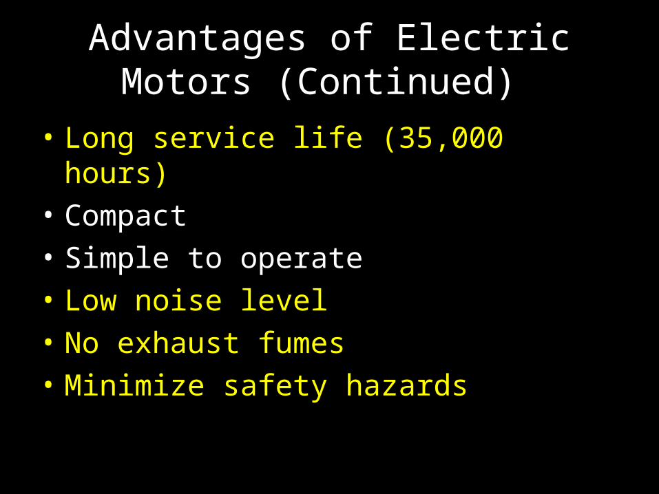
Advantages of Electric Motors (Continued)
• Long service life (35,000 hours)
• Compact
• Simple to operate
• Low noise level
• No exhaust fumes
• Minimize safety hazards
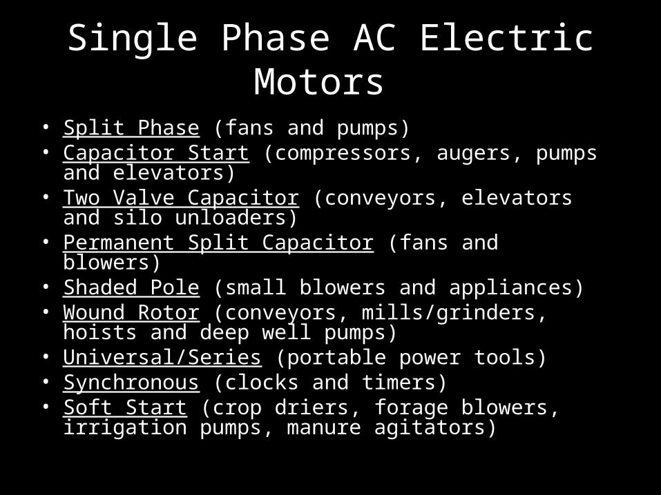
Single Phase AC Electric Motors
• Split Phase (fans and pumps) • Capacitor Start (compressors, augers, pumps and
elevators) • Two Valve Capacitor (conveyors, elevators and silo
unloaders) • Permanent Split Capacitor (fans and blowers) • Shaded Pole (small blowers and appliances) • Wound Rotor (conveyors, mills/grinders, hoists and
deep well pumps) • Universal/Series (portable power tools) • Synchronous (clocks and timers) • Soft Start (crop driers, forage blowers, irrigation pumps,
manure agitators)

AC Electric Motor Power (P) in Watts
• Single Phase Motors: – P = E x I x PF
• Three Phase Motors:– P = 1.73 x E x I x PF – Where:
• P = Power in (Watts)• E = Electromotive force in (Volts)• I = Current flow in (Amps) • PF = Power Factor

Power Factor (PF)
• The power factor of an AC electric power system is defined as the ratio of the active (true or real) power to the apparent power. – Where:
• Active (Real or True) Power is measured in watts (W) and is the power drawn by the electrical resistance of a system that does useful work.
• Apparent Power is measured in volt-amperes (VA) and is the voltage on an AC system multiplied by all the current that flows in it. It is the vector sum of the true and the reactive power.

Power Factor (PF)
• For purely resistive loads like incandescent lighting and heating elements the power factor is 1.0 so in these special cases:– Power (P) = E x I = Watts
• The power factor for inductive or capacitive loads such as electric motors varies by motor type, hp rating, and the mechanical load on the motor. Power factor can vary from 0.3 for unloaded fractional hp motors to nearly 1.0 for large capacitor run motors.

Electric Motor Efficiency
• Efficiency The power output divided by the total power consumed = – Useful power output / Total power input.
• For single phase motors (%) =– ((Rated hp x 746 W/hp) / (E x I x PF)) x 100
• For three phase motors (%) =– ((Rated hp x 746 W/hp) / (1.73 x E x I x PF)) x 100

Electric Motor Data Plate
Gives critical data such as: Voltage, Amps, Phase, Hertz, RPM, Power Factor
and Duty Rating

25 hp Electric Motor Example
• Actual power consumed
• (P) Watts (3 phase) = 1.73 x E x I x PF
• P = 1.73 x 230 x 59.4 x 0.843 = 19,925 W
• Theoretical power output
• 25hp x 746 W/hp = 18,650 W
• Efficiency (%)
• (18,650 / 19,925) x 100 = 93.6%

Electric Motor Data Plate
Notice how the calculated efficiency is exactly the same as the nominal efficiency on the data
plate!
Starting Current (Amps)
• Refer to the electric motor characteristics table in the handout!
• Notice that an electric motor can draw between 1.5 and 8 times the full-load current at start up.
• When sizing conductors and overload protection devices for electric motors multiply the full-load amperage by 1.25 or 125% to find the minimum ampacity.
Ampacity: the current (amps) a conductor can carry without exceeding it’s temperature rating.

(Electrical Wiring)

AC Phases
• Residential electrical service is exclusively single phase.
• However some agricultural applications e.g. some large electric pumps, require three phase power.
• Farms and shops will often have high voltage three phase electrical service.
• Three phase is more complicated to wire and should be handled by a qualified electrician
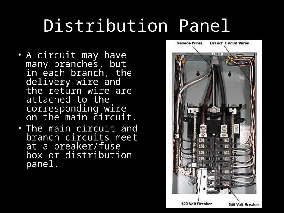
Distribution Panel
• A circuit may have many branches, but in each branch, the delivery wire and the return wire are attached to the corresponding wire on the main circuit.
• The main circuit and branch circuits meet at a breaker/fuse box or distribution panel.

Types of Branch Circuits
• General purpose: 120 V 20-Amps or less.– Permanent lighting and appliances. – Convenience outlets (<1,500 Watts)
• Individual: 120 or 240 V – All motors ½ hp or larger– Appliances over 1,500 Watts – All 240 V applications – Continuous service equipment (incubators, milk
coolers, brooders, etc.) • The minimum recommended AWG for both
types of branch circuits in agricultural applications is 12 gauge (copper).

Protection of Branch Circuits
• Each branch circuit is protected by it’s own fuse or circuit breaker.
• The over-current protective device is selected in accordance maximum current (Amps) that can be carried by the gauge wire used in the circuit.

Over-current Protective Devices
Circuit Breakers automatically open the circuit when current flow exceeds the breaker rating
Fuses have a circuit opening “fusible member” that is directly heated and destroyed by the passage of too much current
Fuses and circuit breakers protect the wires and equipment not people!

Ground Fault Circuit Interrupter (GFCI)
• Fuses and circuit breakers are designed to protect equipment and wiring from current overloads. (These are fairly slow to react)
• A GFCI is designed to protect people from stray current and shorts.
• The GFCI compares the current on the hot wire to the current on the neutral wire, if the amperage is not equal the GFCI cuts off the current immediately!

Designing a Single Phase Branch Circuit
1. Determine the electrical load
2. Measure the length of the run (one-way)
3. Select the appropriate wire gauge
4. Select the appropriate wire insulation type
5. Select the appropriate over-current protective device
For all convenience outlets use a GFCI

Electrical Load for General Purpose Branch Circuits
A. Count the number of lamps or appliances that will be used on the circuit and note the wattage of each.
B. Add up the number of watts used on the circuit.
C. For a 120 V AC circuit divide the watts by 120 to determine the amp load
D. Recall that Watts = Volts X Amps
Electrical Loads for Individual Branch Circuits
A. Find the full-load current (Amps) for the motor.
B. To adjust for starting current multiply the full-load current (Amps) by 1.25 or 125%
Measure the length of the run
• Measure the distance from the main circuit box to the end of the branch circuit to be wired.
• Recall that long runs will cause a voltage drop on the circuit ( No more than a 2% Voltage Drop should be allowed)
• For example a five amp load needs only 12 gauge wire to go 50 feet, but will require a 10 gauge wire at 100 feet.
Voltage Drop
• Is the reduction in voltage between the power supply and the electrical load. This loss occurs any time electricity flows on a conductor such as a wire. Voltage drop is equal to the product of the current (A) and the resistance (Ω) of the conductors in the circuit.
• Voltage Drop (%) = ((I x R) / E) x 100

Wire Gauge for (120 Volt) AC Single Phase (Lighting & Outlets)
Amp Load
30’ Run
100’ Run
200’ Run
300’ Run
400’ Run
500’ Run
5 amp
12 ga 12 ga 10 ga 8 ga 6 ga 6 ga
10 amp
12 ga 10 ga 6 ga 4 ga 4 ga 3 ga
15 amp
12 ga 8 ga 4 ga 4 ga 2 ga 1 ga
20 amp
12 ga 6 ga 4 ga 2 ga 1 ga 0 ga
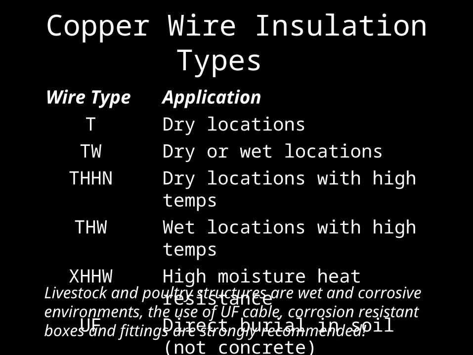
Copper Wire Insulation Types
Wire Type Application
T Dry locations
TW Dry or wet locations
THHN Dry locations with high temps
THW Wet locations with high temps
XHHW High moisture heat resistance
UF Direct burial in soil (not concrete)
Livestock and poultry structures are wet and corrosive environments, the use of UF cable, corrosion resistant boxes and fittings are strongly recommended!
Making connections
• There are a number of ways to make electrical connections:– Screw terminals– Electrical solder – Solder-less connections – Wire nuts – Splices – Etc.

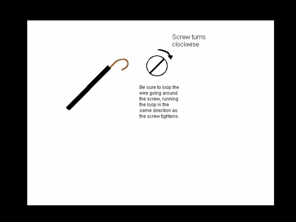
Screw terminals
• Commonly found on switches, outlets, and lamp holders.
• Note the clockwise direction of the connection

Soldering connections
• Solder is an excellent way to make electrical connections.
• Connections are sure and permanent.

Solder-less connections
• These connections are fast and secure, but must be crimped properly in-order to give good results

Wire nuts
• Wire nuts are used extensively in wiring homes and agricultural structures.

Wire splices
• Wire splices are often used as a last resort when one of the preceding methods will not work.

Splicing multiple wires
• When more than one wire is to be spliced the splices should be staggered to prevent a short circuit.
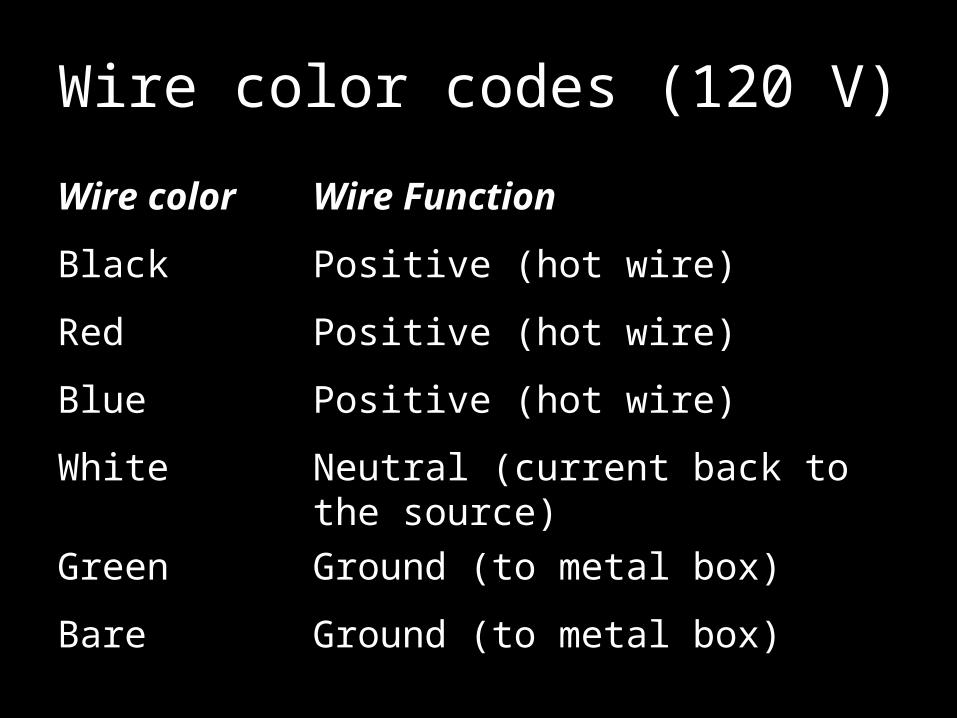
Wire color codes (120 V)
Wire color Wire Function
Black Positive (hot wire)
Red Positive (hot wire)
Blue Positive (hot wire)
White Neutral (current back to the source)
Green Ground (to metal box)
Bare Ground (to metal box)
Wiring
• Switches
• Lamp sockets
• Outlets

Switches
• Single pole –
• Three way –

Single pole switch

Three-way switch

Three-way circuit

Three-way circuit

Lamp sockets

Convenience outlet

Convenience outlet

Convenience outlet
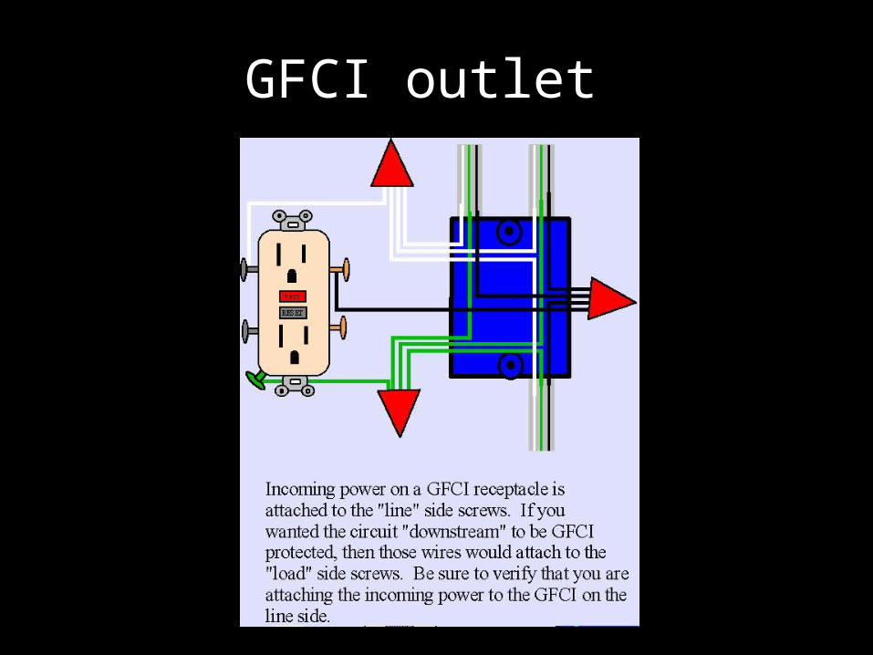
GFCI outlet
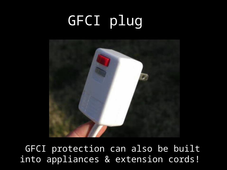
GFCI plug
GFCI protection can also be built into appliances & extension cords!
Circuit Failures
• Short– A short circuit occurs when two or more wires come in
contact with each other that should not.– May result from worn insulation or a wire becoming
unhooked.– Causes a by-pass to be created in the original circuit,
reducing the resistance of the circuit.– When the resistance is reduced, current flow or
amperage increases producing excessive heat.– Heat can melt insulation, cause circuit breakers to
trip, fuses to melt or even damage to electrical equipment.

Circuit Failures
• Open Circuit– An interruption or break in the flow of
electricity.– This can occur when a conductor is
accidentally cut, comes loose from its connection or corrosion has created too much resistance in the circuit.
– Construction workers digging into underground cables is a common occurrence for the utility companies.