electrical resistance heating elements: … electrical resistance heating elements: an overview in...
TRANSCRIPT

1
ELECTRICAL RESISTANCE HEATING ELEMENTS: AN OVERVIEW
In the field of electrical resistance heating, a variety of materials are available for use
as heating elements. They include METALLIC ALLOYS (Nickel-chrome, Iron-Chrome-
Aluminum, Tungsten, Molybdenum, and Tantalum), CERAMIC MATERIALS (Silicon
Carbide, and at one time Zirconium Oxide), CERAMIC METALS (Molybdenum Disilicide,
Lanthanum Chromite), PRECIOUS METALS (Platinum and Platinum Rhodium Alloys),
and GRAPHITE/CARBON based materials. These materials may be divided into two
separate groups; those that can operate at elevated temperatures in the presence of oxygen
and those that must be protected from oxygen. Tungsten, molybdenum, tantalum, and
graphite fall into the second category. Since our intention is to cover those items that can be
used in air and certain protective atmospheres, we shall give the oxygen-sensitive materials
a quick review while concentrating on the other materials in depth. In a like manner, since
PRECIOUS METALS and Lanthanum Chromite have rather limited usages due to costs,
physical constraints or contamination issues, they will receive only a cursory examination.
As Zirconium Oxide is believed to be commercially unavailable at this time, only a passing
mention of it will be made.
We will concentrate on Nickel-Chrome and Iron-Chrome-Aluminum for the
METALLICS, Silicon Carbide for the CERAMICS and Molybdenum Disilicide for the
CERAMIC METAL. In the charts and graphs presented in this paper, the following
abbreviations will be used:
Nickel-Chrome NiCr
Iron-Chrome-Aluminum FeCr
Silicon Carbide SiC
Molybdenum Disilicide MoSi2

2
It is hoped that by providing a brief explanation of how these materials function,
their limitations, and basic design considerations, the reader will be able to choose the best
material for a given application. It should be noted that a variety of factors not covered in
this paper could affect operational characteristics of these materials. Once a preliminary
examination of needs has been completed, the user should contact a reputable vendor to
review the application in depth. As specifications may change or new products may be
developed, this presentation should be used only as a guide; the reader is urged to contact
the manufacturers of these products for current detailed specifications/characteristics.
Several factors should be examined in choosing a heating element. They are
temperature, atmosphere, life and power or heat load required. The temperature referred to
is actual element operating temperature. It is based on the inter-relationship of furnace
temperature, element watt loading, and the ability of the element to radiate the heat
generated. Design information is available from a variety of sources showing the effects of
element placement on radiation ability and the relationship of furnace temperature versus
element watt loading. An energized element will always be operating at a higher
temperature than its surrounding "ambient." The higher the watt loading, the greater the
temperature differential or "head" generated. As the furnace temperature increases, the watt
loading must decrease to prevent element overheating. Fig. 1 shows this relationship for
freely radiating elements in air.

3
Atmosphere is important in that at increasing temperatures, materials react
differently to various compounds. A system that works very well at one temperature in air,
may fail quickly if applied in a different atmosphere at the same temperature. Figure 2
shows the maximum element temperatures in various atmospheres for freely radiating
elements.
Be aware that dew points and vacuum levels can drastically decrease the listed
temperatures. Please note that the “KanER” refers to a proprietary molybdenum disilicide
based material developed by Kanthal to specifically work in vacuum, hydrogen, and other
reducing atmospheres.
05
101520253035
WATT
S PER
SQUARE CEN
TIMET
ER
FURNACE TEMPERATRE, DEGREES C
FIGURE 1
MAXIMUM WATT LOADINGS
MOSI2
SIC
FECR
NICR

4
Service life of the element is also an important economic consideration. One must
determine whether the elements are to last for years, months, or weeks. With any given
element, the higher the operating temperature, the shorter its lifetime. Thus, for a long life,
it is implied that the element should have a low head temperature with respect to furnace
temperature. This is accomplished by decreasing the watt loading. The down side of this
equation is that by lowering the element loading, we must add more elements to meet the
heat load requirements of the furnace. These additional elements yield higher initial cost,
and their number may be restricted due to space limitations in the furnace.
Finally, we have to consider the power or heat load requirements of the furnace. The
power required is determined by process temperature, amount of material to be heated, heat
up rates, and furnace losses. Restrictions are normally placed on the amount of power (KW
or kilowatts) that can be placed on the furnace walls. These restrictions are based on
element configuration, placement, material type, and furnace temperature. Figure 3 shows
this relationship for a freely radiating Iron-Chrome-Aluminum element versus one housed in
slots, and the same relationship for a Molybdenum Disilicide element mounted parallel to
(along) and perpendicular to (across) the walls.

5
REVIEW OF MATERIALS
A general review of materials indicates their advantages and limitations.
I. METALLIC ALLOYS
These materials (Nickel-Chrome and Iron-Chrome-Aluminum) are often the easiest
to use and the least expensive. Unfortunately, they also have the lowest operating
temperature in an oxidizing atmosphere.
Metallic alloy materials are fairly rugged with respect to mechanical and thermal
shock. Their resistance remains relatively constant with respect to temperature and also
with respect to service life. These two factors combine to produce a product that is very
easy to control, yielding what is generally a rather simple and inexpensive power supply.
This fact can in turn have a significant effect on the overall capital costs of a project, making
this class of materials very attractive. Thermal cycling does not present a significant
problem. Most of these alloys are available in wire, strip, rod and tube forms.
0
20
40
60
80
100
120
140
160
800
900
1000
1100
1200
1300
1400
1500
1600
1700
1800
KW/SQUARE MET
ER
FURNACE TEMPERATURE DEGREES C
FIGURE 3
MAXIMUM WALL LOADING VERSUS MOUNTING
FeCr Grooves
FeCr ROB
MiSo2 Along
MiSo2 Across
6
A. NICKEL-CHROME ALLOYS
These groups of alloys are among the oldest electrical heating materials and are still
widely used today. They are fairly ductile, have good form stability, and hot strength. The
three most common compositions used for heating applications are A.S.T.M. "A" grade
(80% nickel, 20% chromium), A.S.T.M. "C" grade (60% nickel, 26% chromium, balance
iron), and A.S.T.M. "D" grade (35% nickel, 20% chromium, balance iron). There is a
fourth, rather recent, alloy gaining widespread use that has a typical mix of 70% nickel and
30% chromium. It should be noted that the above A.S.T.M. grades are specified minimum
mixtures and the actual alloy compositions can vary widely among vendors. Of these
various alloys, the 70/30 material is listed as having the highest maximum element
temperature of 1250°C in air, and in most cases would be limited to a maximum chamber
temperature of 1150°C. It generally has poorer ductility than the more common A.S.T.M.
“A” grade alloy, and was developed primarily to combat "GREEN ROT" (an intergranular
oxidation of chromium experienced by the other A.S.T.M. grades of nickel-chrome
materials when used in either exothermic or endothermic atmospheres in the temperature
range of 1500O to 1800°F). As indicated, the A.S.T.M. “A” grade material is the more
common alloy and is limited to a maximum element temperature of 1200°C with a
maximum chamber temperature of 1100°C. This is the material listed as NiCr in the
enclosed charts and graphs. The “C” grade material is rated for 1125°C with chamber
temperatures typically 1000°C maximum. The “D” grade is listed at 1100°C with chamber
temperatures around 950°C maximum.
B. IRON-CHROME-ALUMINUM
These alloys are typified by a composition of 72.5% iron, 22% chrome, and 5.5%
aluminum. The higher grades made by traditional melt technology have limiting
temperatures of 1400°C on the element with chamber temperatures typically 1300°C. There
are other grades available with lower use temperatures in which the aluminum content has

7
been reduced and the balance is made up with iron. These alloys were introduced in
Scandinavia in the early 1930's and their use as a replacement material for nickel-chromes
has been on the increase. Iron-chrome-aluminum alloys typically have a higher use
temperature, higher resistance, and lower density than nickel-chromes. Generally, when
properly applied, these features yield a less expensive, longer-lived element than a
comparable nickel-chrome design. On the down side, Iron-chrome-aluminum alloys suffer
from a lower hot strength, reduced ductility, and embrittlement with use.
C. IRON-CHROME-ALUMINUM, PM GRADES
In the past few years, iron-chrome-aluminum alloys have been introduced that use
powder metal technology in their manufacturing process. Typically, these materials start
with a high-grade iron-chrome-aluminum alloy made by conventional melt technology. The
resulting ingot is then turned into a powder and compressed into a billet either by a hot
isostatic press or, more rarely, a cold isostatic press operation. This billet is then used to
produce the final wire, strip, or tube product. The advantage gained by this extended and
fairly expensive process is an iron-chrome-aluminum product that has greatly improved hot
strength and a higher end use temperature. In one case, the resultant maximum element
temperature is listed at 1425°C while the parent alloy is listed at 1400°C. Figure 4 shows
the results of a sag test comparing one of these powder metal based iron-chrome-aluminum
alloys (APM), a standard high temperature iron-chrome-aluminum (FeCr), and an A.S.T.M.
Grade “A” nickel-chrome (NiCr) material.

8
The tests were performed on 4 mm diameter rods in a horizontal position, supported at 200
mm intervals, and exposed to 1200°C. The results are shown in millimeters of sag plotted
on the vertical axis against time on the horizontal axis. As indicated, the PM grade material
is superior to its parent alloy.
II. SILICON CARBIDE
Silicon carbide (SiC) exists only as a solid and, as it has no liquid phase, the material
is rigid at all practical operating temperatures. This means that silicon carbide elements can
be installed horizontally or vertically, without any additional supports, which simplifies the
design of the equipment in which they are fitted. Silicon carbide elements are manufactured
by various processes, the most common being recrystallization and reaction-bonding. The
resulting element hot section is not 100% dense, and so the element can react with the
surrounding atmosphere not only on its surface but also throughout its pore structure. This
differentiates SiC elements from other element types, which are fully dense, and can react
only on the surface of their hot section. Reaction between the silicon carbide material and
the atmosphere reduces the conductive cross-section of material that carries the electric
current, and so the resistance of the elements increases with time. This process is generally
known as aging. Operating under ideal conditions, the resistance of a high quality silicon
carbide may increase by as much as 300% before it reaches the end of its useful life. In air,
0
5
10
15
20
25
30
0 100 200 300 400 500 600
MM OF SA
G
HOURSFIGURE 4
SAGGING TEST
FeCr STD
NiCr80/20

9
or other oxidizing conditions, the predominant reaction is the oxidation of SiC, to form SiO2
(silica) and CO2 gas.
Silicon carbide elements also change in resistance with temperature. The resistance
is fairly high at room temperature, falls with increasing temperature to a minimum value at
about 800°C, and then increases with temperature. Minor variations in impurities present in
the element have a significant effect on the cold resistance value. Therefore, room
temperature resistance measurements give no indication of the actual element resistance at
operating temperature. For this reason, any resistance measurements should be taken at
element temperatures above 800°C and should be based on voltage and current readings
taken from the element. Specified element resistances are measured at element temperatures
between 1000O and 1090°C, depending on manufacturer. Figure 5 shows this characteristic.
FIGURE 5
The above characteristics, aging and temperature dependent resistance imply the
need for a variable voltage power supply capable of increasing the output voltage by a factor
of two (2). This approach allows for the aging, yet allows the voltage to be limited during
the negative portion of the resistance curve. In the past, a large, complex and expensive
power supply typically was used to provide proper and efficient operation of most silicon

10
carbide systems since the elements generally require a starting voltage much lower than the
available line voltage.
More recently, advances in the quality of elements, resulting in lower rates of aging,
coupled with developments in SCR technology, have permitted far more simple and less
expensive equipment to be employed, and many industrial and laboratory furnaces today can
be controlled using SCRs alone, without the need for transformers.
Typical silicon carbide has a maximum recommended element temperature of
1650°C (~1600°C chamber temperature) although molybdenum disilicide elements will
generally be preferred for prolonged use above 1500-1550°C. Due to its granular structure
and the thermal expansion characteristics of silica, cycling of silicon carbide elements used
in air tends to increase the aging rate. However, SiC elements are used successfully in a
wide range of periodic applications. There are some silicon carbides that are available
(developed in Europe) which are designed for continuous or intermittent use up to 1600oC
furnace temperature. This material is limited with respect to physical sizes available.
Generally confined to laboratory applications, this material has recently been expanding into
the industrial marketplace.
Silicon carbide is susceptible to mechanical shocks and, depending upon
manufacturer and type of material, has thermal shock resistance ranging from moderate to
excellent. Therefore, care should always be taken with handling and installation, in addition
to rate of power application. It is manufactured in straight rods, multi-leg elements, or as
spiral cut elements with electrical connections at one or both ends.
III. MOLYBDENUM DISILICIDE
Molybdenum disilicide is made using a powder metallurgy process in which certain
ceramic and metallic components are added to the base material to improve its mechanical
characteristics without degrading its oxidation resistance. When originally developed, this
material was limited to a maximum element temperature of 1700°C and is still available in

11
this grade today. Over the years, various suppliers have developed improved grades of this
material and it is now available with element limited temperatures of 1800 and 1850°C. In
addition to the higher temperature grades, the material is also available in a variety of shapes
that has increased the usefulness and flexibility of product application.
Molybdenum disilicide exhibits a drastic increase in resistance with temperature, on
the order of ten to fourteen (10-14) times at maximum use temperature in comparison to
room temperature. Unlike silicon carbide, the resistance of this material remains relatively
stable over the lifetime of the element and thus this material does not age. The power
supply is generally less expensive than one for silicon carbide since, although it must limit
current during cold start up conditions, it does not have to increase voltage to allow for
element aging.
Molybdenum disilicide material is somewhat brittle and sensitive to mechanical
shock. This brittleness will increase with use. Thermal shock is generally not a problem as
long as the start-up current is limited to specified maximum values. Unlike silicon carbide,
cycling generally does not present a problem, as long as the element is free to move within
its support structure in response to thermal expansion. Since the material has poor hot
strength, it has been traditionally supplied in a "U" shape that is freely suspended in a
vertical mode. It can be mounted in a horizontal mode, provided it is properly supported
and element temperatures are limited to manufacturer's specified values.
As mentioned, this material has recently been made available in a series of non-
traditional shapes such as rounds, half rounds, and pancake designs. To accomplish this, the
material is prepackaged with a special insulation/support structure. This enables the
material to be supplied in these shapes and yet be properly supported. Due to interactions
between the element and insulation at elevated temperatures, these packages have
traditionally been limited to chamber temperatures between 1550 to 1650°C in cyclic
operations.

12
Kanthal ER, RA, HT, and NC, I Squared R Moly-D XLR
Kanthal and I Squared R have developed several variants of their standard
molybdenum disilicide materials that are designed for use in specific atmospheres, cyclic
operations or areas requiring a very low degree of process contamination. These variations
use oxide manipulation or composition along with a high purity base material to accomplish
the specific characteristics needed for each application/element selection. As these materials
are constantly evolving, it is recommended the reader contact the manufacturer for exact
specifications. However, a brief overview of each of these variants will be offered for
familiarization purposes only.
Kanthal ER:
This material forms a pure aluminum oxide (Al2O3) as a protective coating rather
than the silicon dioxide (SiO2) formed by the standard grades of molybdenum disilicide.
This alumina oxide coating allows the ER material to operate in vacuum, dry hydrogen, and
other reducing atmospheres at higher temperatures than normally allowed for standard
grades of molybdenum disilicide. It has a maximum element temperature of around 1580°C,
depending on atmosphere and dew points.
When compared to the standard 1800 grade molybdenum disilicide, the ER material
has a higher resistance at room temperature and a much flatter resistance versus temperature
curve. This material typically has a 1.67 times increase in resistance from room temperature
to maximum element temperature. The resistance curves for the standard 1800 grade and
Kanthal ER cross around 1350°C. This higher resistance at lower temperatures implies that
when the power supply is operating in a current limited mode, higher wattage can be
generated with ER than would typically be expected with the standard grades of

13
molybdenum disilicide, up to the resistance crossover point of 1350°C.
The primary use of this element will be in an atmosphere containing hydrogen, inert
gases, endogas, rough vacuums, reducing gases or any combination thereof during furnace
operation. Applications requiring low silica levels inside the furnace chamber also show
promise. The material also shows few corrosion issues when used with high alumina
supports.
Currently, the ER material is limited to smaller element shank diameter sizes than
standard grades of molybdenum disilicide but is available in both two (2) and four (4) shank
element shapes as standard forms. It can be supplied as part of Kanthal’s Superthal
element/insulation package.
Kanthal RA & I Squared R Moly-D XLR
Standard forms of molybdenum disilicide generally exhibit poor performance with
respect to lifetimes and have significantly reduced allowable element temperatures when
operated in pure nitrogen atmospheres. When the element temperature reaches 1250 to
1550°C, depending on dew points and other factors, nitration of the ceramic base material
generally occurs. Typically, any protective glaze of SiO2 will be consumed, allowing the
silicon in the silicide of the element to react with the nitrogen. This process forms silicon
nitride (Si3N4), which damages the element by scaling and other processes. Kanthal RA and
Moly-D XLR are designed to specifically combat this problem. They can operate up to
100°C higher than other grades of molybdenum disilicide with a maximum element
temperature of 1700°C in a pure nitrogen atmosphere, depending on dew points. In one-to-
one comparison tests, these grades may demonstrate up to a 100% longer life than standard

14
grades of molybdenum disilicide when used in the applications and atmospheres they were
designed for. The standard forms for these materials currently are either two (2) or four (4)
shank shapes, but can be supplied as part of an integrated fiber module heater package.
They are restricted to the larger element shank diameters.
Kanthal HT:
This variant is designed to produce a very thin oxide layer of SiO2 when compared to
the other standard forms of molybdenum disilicide. The standard forms of molybdenum
disilicide (1700, 1800, and 1900) will form a very thick SiO2 oxide layer with use. This
SiO2 oxide has a different coefficient of expansion than the MoSi2 base element material.
When cooled down to room temperature, this differential coefficient of expansion can create
considerable tension on the element and, depending on the oxide thickness (which is
time/temperature dependant), it is possible for the element to fail mechanically via cracked
or broken element shanks. By limiting the oxide thickness, the forces applied to the element
shanks are greatly reduced when compared to standard forms of molybdenum disilicide.
This allows the material to operate successfully at rather high element temperatures (1830°C
maximum in air) in cyclic operations, while exhibiting a longer life than standard forms of
molybdenum disilicide.
As mentioned earlier, interactions between molybdenum disilicide and the refractory
used in Kanthal’s Superthal element package limit the chamber temperature to around 1500
to 1650°C. One of the main issues is the SiO2 oxide bonding with the refractory at element
temperatures above 1600 to 1650°C. Thus, when the system is cooled down, the element is
essentially cemented in place and not free to move. This generally leads to element failure
15
due to cracking or breaking of the element shank. The thinner oxide layer of the HT variant
significantly reduces this issue allowing for higher operating temperatures when used in the
Superthal package. The 1500°C lower limit specified is typical for the standard grades of
molybdenum disilicide, while the higher 1650°C rating is for applications using the HT
material.
At present, the material is limited to the smaller element shank diameters when
compared to standard forms of molybdenum disilicide. It is available in either two (2) or
four (4) shank element shapes as standard forms and, as discussed in the preceding
paragraph, is available in the Superthal element package.
Kanthal NC:
This variant is based on Kanthal’s standard 1800 grade molybdenum disilicide
material and is identical to it with respect to electrical characteristics. From a mechanical
standpoint, it has a 25% higher bending strength than the standard 1800 grade material at
room temperature. It is essentially an 1800 grade material that is produced from high purity
ceramic/metal mix in which the metal content is either reduced or refined (iron has been
reduced to a third of the standard 1800 grade levels). This reduced metal content, coupled
with an oxide that adheres very tightly, yields an element that introduces very little
contamination into the furnace atmosphere. This feature is highly desirable in the
production of electronic components and in various research applications
Kanthal NC has a maximum element temperature of 1800°C. At this time it is
available only in the smaller element shank diameters when compared to the standard
1800°C grade material, and comes only in a two shank element form as standard.
16
Lanthanum Chromite
Lanthanum chromite heating elements have had limited use in the United States. The
majority of these heaters are manufactured in Russia and the Peoples Republic of China with
others being produced in Japan and France. These types of heaters have been around since
the early 1970’s and seem to have their main application in lab scale equipment. By and
large, there are other elements that can be used for the same applications that are either
cheaper, more readily available, or just perform better. Depending on the vendor, rather
special mounting hardware and special power supply requirements may be required. It
should be noted that most of the French sizes may be wired in such a way as to allow them
to be powered by line voltage, avoiding the expensive power supply requirement. One area
of accepted use was in certain areas of the Far East where they were used to join optical
fiber together. It has similarities with molybdenum disilicide in that it does not age with
use, can be used up into the 1800oC range (vertical mounted only above 1200oC), and is
sensitive to mechanical shock. Major differences between molybdenum disilicide and this
material include sensitivity to thermal shock, a drastic resistance decrease as temperature
increases, and it is somewhat easier to form into complex and small shapes than
molybdenum disilicide. It is this formability that has led to its use in the fiber optics
application mentioned above. Small heaters have been developed that can concentrate their
heat flux on a small area of the fiber. Because there are now prototype molybdenum
disilicide and silicon carbide heaters available for this fiber application, lanthanum
chromites dominance in this area may soon be challenged.
A potential problem with this material is the hexavalent chromium [Cr(VI)]
contamination that occurs at temperatures above 1600oC. Some of the chromium will
sublimate and deposit onto the refractories as well as the product inside the furnace. Since
hexavalent chromium is a known carcinogen, the contaminated refractories as well as the
elements are to be considered hazardous waste and must be disposed of accordingly.

17
IV. ZIRCONIUM OXIDE
This product was introduced in the early 1970's and allowed chamber temperatures
in excess of 2000°C. It was typically sourced from Sweden or China. The material was
quite expensive, very sensitive to mechanical and thermal shock, limited to vertical
mounting and had a maximum hot length of around six (6) inches. The elements had to be
preheated to between 1000 to 1100°C before they became electrically conductive, which
required a separate heating system. This feature, coupled with long duration controlled heat
up/cool down rates, dictated a rather expensive power supply for successful operation.
Since the only practical hot face insulation that can withstand these temperatures is a
zirconium oxide based brick (which becomes electrically conductive at typical furnace
operating temperatures), great care had to be taken in dealing with clearances between
bricks, elements and a rather complex, expensive element support structure least
element/system faults to ground occur with a corresponding negative impact on the internal
refractories and element failure.
Almost all the applications were for a limited number of small, highly specialized
laboratory furnaces used for nuclear or advanced aerospace programs and in the production
of artificial gemstones, such as sapphires. As such, the material was deemed to be a
nonviable product from an economic standpoint and, at this time, the writer is unaware of a
readily available commercial source for zirconium oxide heating elements.
OXIDE FORMATION
One of the most important considerations in the use of any heating material is
reaction with oxygen at elevated temperatures. With some materials, such as molybdenum,
tungsten or graphite, this oxidation process continues until the material is consumed. In
other materials, a protective oxide layer forms, that, unless disturbed, inhibits further
18
oxidation and may offer protection against attack by other compounds. Oxide formation is
dependent on time and temperature. Generally, for iron-chrome-aluminum alloys,
temperatures above 1000°C should be used to insure a good oxide formation; for nickel-
chrome alloys, 800 to 900°C should suffice.
A. NICKEL-CHROME
This material forms a chromium oxide layer when heated in the presence of air. The
oxide layer is relatively thick and greenish in color. It has a propensity to flake off during
cycling. This flaking exposes the base metal to further oxidation. Eventually the chrome is
depleted, leading to element failure. This flaking can also lead to product contamination
unless the elements are located in such a position that falling oxide will not land on the
product or the elements are encased in protective tubes. The oxide offers little protection
against carbon infiltration and is highly reactive to sulfur.
B. IRON-CHROME-ALUMINUM
These alloys form an oxide comprised mainly of aluminum oxide (Al2O3). Like the
chromium oxide, aluminum oxide is very stable. However, it has one very important
difference. It is very thin and adheres tightly to the base metal, making it less likely to flake
off and lead to product contamination. As the element is thermally cycled, small cracks
may develop in the oxide, which eventually will lead to aluminum depletion in the base
metal. Generally this aluminum depletion occurs at a much slower rate than the chromium
depletion in nickel-chrome materials of similar configuration. The oxide is very resistant to
carbon infiltration and is particularly stable in the presence of sulfur. The oxide is also an
excellent electrical insulator, which is beneficial should element sections inadvertently
touch. This situation can be disastrous in the case of chromium oxide protected materials.
C. SILICON CARBIDE
In the case of silicon carbide, oxide formation actually leads to element failure.
Silicon carbide elements typically have a porosity of 8 to 30%. Oxygen infiltrates the bar

19
and attacks the bridge points, forming silicon dioxide. Although the silicon dioxide tends to
form a protective layer and stop any further oxidation, if the layer is disturbed through
thermal cycling, mechanical abrasion or chemical attack, virgin silicon carbide is exposed to
further attack.
D. MOLYBDENUM DISILICIDE
In the presence of oxygen, this material will form a protective oxide of silicon
dioxide or quartz glass, as does silicon carbide. However, where silicon carbide is rather
porous, molybdenum disilicide is very dense, with a porosity range of less than 1% to as
much as 5%, depending on vendor. Oxidation occurs only on the surface of the element
rather than throughout the entire structure as with silicon carbide. Further, the silicon oxide
is usually very thin, adheres tightly, and rarely flakes off. It offers excellent protection
against further oxidation, as well as protection against various atmospheres.
LIFE
As mentioned, element life is based on factors such as temperature, atmosphere,
mechanical shock, and chemical attack. Because of differences in mounting, operating
cycles and other variables, it is difficult to give an accurate figure for the life of a given
element.
A. METALLIC ALLOYS
In general, the flaking of the chromium oxide on nickel-chrome materials has a
greater effect on base material depletion then the cracking of the aluminum oxide on iron-
chrome-aluminum materials. This, coupled with a higher use temperature, indicates that in
oxidizing atmospheres, for a given watt loading, atmosphere composition, and furnace
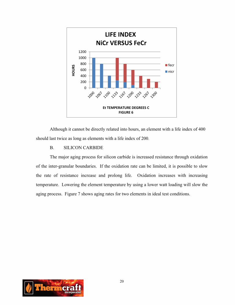
temperature, the iron-chrome-aluminum material should last longer. Figure 6 shows a "life
index" for the two (2) alloys in air.
20
Although it cannot be directly related into hours, an element with a life index of 400
should last twice as long as elements with a life index of 200.
B. SILICON CARBIDE
The major aging process for silicon carbide is increased resistance through oxidation
of the inter-granular boundaries. If the oxidation rate can be limited, it is possible to slow
the rate of resistance increase and prolong life. Oxidation increases with increasing
temperature. Lowering the element temperature by using a lower watt loading will slow the
aging process. Figure 7 shows aging rates for two elements in ideal test conditions.
0
200
400
600
800
1000
1200
HOURS
Et TEMPERATURE DEGREES CFIGURE 6
LIFE INDEXNiCr VERSUS FeCr
fecr
nicr

21
The diagram shows that an element operating at 1000°C has increased its resistance
by a factor 1.5 times over fifteen (15) time units. The same element operating at 1400°C has
increased its resistance by over four (4) times during the same fifteen (15) time units and has
reached the end of its life.
Limiting the rate of oxygen infiltration can also slow oxidation. This can be
accomplished by decreasing the porosity of the element or by providing a coating or through
structure glazing treatment that will seal the element. In the case of coatings and glazes,
they should be non-permeable, have an expansion/ contraction coefficient equivalent to the
base silicon carbide, and not have any harmful secondary element reactions. Both of these
options, densified bars and coatings/glazes, are available. The lower porosity bars, as
presently produced, exhibit an enhanced sensitivity to mechanical and thermal shock. They
have been shown to perform somewhat better under normal conditions, but carry a
significant premium (up to 50% more than standard elements). It is up to the user to
determine if the increased life offsets the increased purchase price. Coatings and glazes also
offer some increased performance but again carry a premium that may not offer an attractive
enough return on investment.
0
1
2
3
4
1 3 5 7 9 11 13 15
% X
100
TIME UNITSFIGURE 7
AGING OF SILICON CARBIDE IN AIR
CONTINUOUS OPERATION
Et =1400C

22
A side benefit of both of these approaches is the performance in corrosive
atmospheres, such as float glass production or calcining of phosphor powder. In the case of
float glass, glazed elements have been developed that have allowed production campaigns to
be increased from seven (7) to over fifteen (15) years and to an industry best of eighteen
(18) years. The densified elements have shown lifetimes on the order of 1.5 to almost 2
times longer than normal silicon carbide in typical phosphor calcining operations.
User actions can also affect element life. First, one may wish to order elements with
matched resistances. Normal production tolerances for US produced elements call for ±20%
on specified resistance; although European tolerances vary by element type from ±10% to
±15%. If two (2) elements of unequal resistance are connected together, they will not share
power equally. In parallel circuits the lower resistance element runs at a higher power level,
which means a higher element temperature and shorter life. The reverse is true of series
circuits. Elements connected in series should be matched to within 5%, and those connected
in parallel should be matched to within 10%. New elements can be matched easily, by
selecting them by calibrated amp or resistance value. By following the above guidelines,
element life may be extended. If one element in a controlled section should fail, all elements
within that section should be changed out and replaced with new elements. This is to insure
resistances of the entire bank are matched. By keeping records of element resistances at
failure, the good elements that were changed out can often be used for spare parts, should
another failure occur at a similar point in the aging process. Because thermal cycling
disturbs the oxide layer leading to a shorter life, operating the furnace continuously could
extend element life. If desired, when not in use, the furnace can be idled around 700°C
chamber temperature without significantly affecting the oxide structure. When mounting
the elements, care should be taken to insure they are able to expand and contract during any
thermal cycling. Care must also be taken to insure that the refractory material does not

23
contact the elements, leading to binding forces being applied to the element during cool
down or major operating temperature set point changes. Terminations should be made in
such a manner that binding forces are not applied to the element. Finally, manufactures
recommendations for handling and storage should be followed to limit mechanical damage.
Failures in the terminal areas can occur. Generally these are heat related. Loose
terminal connections, extraordinary furnace heat losses (in the terminal area) or improperly
sealed passage bricks are typical problems. Replacement of termination straps and/or
connectors, proper sealing of passage bricks, supplying outside cooling air or use of longer
terminals should solve these problems.
C. MOLYBDENUM DISILICIDE
No life figures are given for this material. Most failures are not the result of oxide
formation and flaking, but result from either chemical attack or, more often, mechanical. In
some cases, failure of an element during furnace cool down is interpreted as a poor thermal
cycling characteristic of the material. The true cause of failure is generally induced
mechanical forces caused by the element being constrained in some way, thus limiting its
freedom of movement. After operating for long periods of time, grain growth takes place
that increases the brittleness of this material even further than normal. This induced stress
that may have not been a problem originally, can become more and more critical with use.
As with silicon carbide, terminal overheating can cause element failure. The same
corrective actions for silicon carbide can be applied.
When properly applied, molybdenum disilicide elements have been shown to have
typical lifetimes of two to three (2-3) years in highly cyclic operations; in continuous
operations, three to five (3-5) years is the norm, with some glass operations managing ten
(10) years or more.
24
PACKAGED SYSTEMS
The above discussion has been based on "free standing" elements that are designed
for mounting independently of the insulation system. Various systems are available that
combine the elements and a suitable insulation package in one unit. Generally, these
systems use either nickel-chrome or iron-chrome-aluminum alloys for elements. The
standard shapes are cylindrical, half rounds or flat panels in a variety of sizes, power and
voltage. General construction is either a cast/pressed ceramic support with an optional
insulation package or a vacuum cast form that provides both support and insulation.
Maximum chamber temperatures range from 1100 up to 1400°C for specialized packages
with rather stringent operating limitations.
As mentioned earlier, there are versions that use molybdenum disilicide for the
element, which offer substantially higher operating conditions than the more common metal
alloy based units. Although most of these prepackaged systems carry some sort of a
premium over the cost of separate elements and insulation, they often present significant
savings in engineering and installation costs.
V. OXYGEN SENSITIVE MATERIALS
As indicated these materials include molybdenum, tungsten, tantalum and graphite.
Oxygen sensitive materials can have fairly high use temperatures and watt loading, as long
as they are protected from exposure to oxygen by either an inert atmosphere or proper
vacuum levels. These items all exhibit substantial increases in resistance with increasing
temperature. This characteristic dictates using a power supply that can limit current to
protect not only the elements but also the furnace and power supply from excessive power
during cold start-up conditions. Several of these items also exhibit a fair amount of
sensitivity to both mechanical and thermal shock. An unfortunate aspect of most
applications using these materials is that even for those items not particularly susceptible to

25
thermal or mechanical shock, they use support and structural components that are.
Therefore a slow, controlled ramping function from one operational set point to another is a
desirable feature.
Finally, most of these materials operate at levels lower than standard available line
voltages. This generally translates into a fairly high amperage requirement from the power
supply. All these characteristics indicate the need for a complex and expensive power
supply.
A. MOLYBDENUM
This material was first used in industrial furnaces around 1930, with increasing usage
after 1940. It is available in a wide range of forms, with the most common element shapes
employed being wire, rod, strip, and on occasion, tubes.
This material has a strong affinity for oxygen at elevated temperatures and can only
be heated in the presence of a vacuum, reducing (dry hydrogen or cracked ammonia), or
pure inert atmosphere. Molybdenum starts to oxidize between 250 to 300°C with the
formation of molybdenum dioxide (MoO2) that will offer a limited amount of protection
against further oxidation up to around 600°C. At this point the molybdenum dioxide
converts to molybdenum trioxide (MoO3), which becomes dominant.
Molybdenum trioxide is very volatile and readily boils off, exposing the base metal
to further oxidation. At around 800°C catastrophic oxidation occurs with clouds of
molybdenum trioxide being generated. With respect to atmosphere purity, an argon
atmosphere containing 45 to 50 PP of oxygen will lead to rapid oxidation of molybdenum at
temperatures around 1200 to 1300°C. Decreasing the oxygen content to 4 to 5 PP should
lead to a successful application. In general, to prevent oxidation problems, never expose
molybdenum to oxygen at temperatures over 400°C.
As indicated earlier, molybdenum has a rather significant increase in resistance from
room temperature to operating temperature. Depending on specific composition, this
26
increase could be on the order of ten (10) times or more from 20°C to 1900°C.
Most common forms of molybdenum are made from a powder that is compressed
and then either extruded, drawn or molded into the desired shape. When new, the material is
fairly ductile and easy to work with. However, when molybdenum has been heated to
around 950°C to 1000°C it starts to recrystallize, and at 1500°C spontaneous crystal growth
occurs. While at temperature, the material remains ductile but once cooled, this crystal
growth phenomenon causes the material to become quite brittle. Depending upon the actual
temperature reached and time spent at temperature, the ductile to brittle transition point can
range from as low as 20°C for unheated material up to 150°C for completely recrystallized
molybdenum. Thus, after heating, molybdenum becomes very sensitive to both mechanical
and thermal shock.
When properly applied, molybdenum can be used in applications having chamber
temperatures up to 1900°C. However, it experiences a sharp reduction in strength and
hardness at elevated temperatures. The creep strength is also strongly dependant on
temperature. These characteristics indicate the requirement for a significant amount of
physical support for the elements to insure proper operation. Unfortunately, molybdenum
also has a marked propensity to react strongly with many common furnace ceramics at
elevated temperatures, leading to element failure. As a result, firebrick is typically limited
to a maximum of 1200°C when used with molybdenum, while very pure Al2O3 has a history
of very successful usage at 1700oC.
This material is commonly used in dry hydrogen, dry cracked ammonia and very
pure inert (argon or helium) atmospheres to 1900°C and, in some instances, even higher
temperatures. In vacuum levels of less than 10-2 torr, molybdenum can be used to 1700°C
but in high vacuum applications, such as less than 10-4 torr, molybdenum evaporation
becomes considerable between 1600 to 1700°C and excessive around 1800°C. Oxidation is
also a problem around 700°C when exposed to water vapor and at 1000°C in the presence of
27
carbon dioxide (CO2). Carbon monoxide (CO) and many hydrocarbons will cause surface
carbonization starting between 1000 to 1200°C.
B. TUNGSTEN
Tungsten exhibits many of the same characteristics as molybdenum with respect to
electrical, mechanical, chemical and thermal properties. It is available in the same general
physical forms as molybdenum. Tungsten is somewhat less ductile than molybdenum and is
therefore harder to work with. It has embrittlement, mechanical and thermal shock problems
that are caused by the same recrystallizing process that affects molybdenum.
One important difference is a much higher melting point for tungsten. This yields
both higher use temperatures and higher vacuum levels than are possible for molybdenum.
When correctly applied with the above defined reducing and inert atmospheres, maximum
use temperatures of 2500°C are quite common. In vacuum levels of less than 10-2 torr, it can
be used up to 2000°C; in levels of less than 10-4 torr, strong tungsten evaporation occurs
around 2400°C and above. Oxidation starts around 500°C, with catastrophic oxidation
occurring around 1200°C.
C. TANTALUM
Tantalum can only be heated in an inert atmosphere or in a vacuum of less than 10-4
torr. This substance shows a strong affinity for bonding with many of the gas molecules
found in common industrial heating atmospheres. When heated in the presence of hydrogen,
oxygen, nitrogen, or carbon, both gas absorption and chemical reactions occur, leading to
the formation of hydrides, oxides, nitrides, or carbides. These reactions result in tantalum
erosion and/or embrittlement. Of these compounds, the hydride formation is reversible so
that heating in a high vacuum can soften tantalum that has become brittle due to exposure to
hydrogen. To some extent, tantalum oxide can also be removed in a similar fashion, owing
to its high vapor pressure characteristic. Because of this high reactivity to certain gases and
the fact it can be somewhat "recycled", in addition to being used as heating elements and

28
heat shields, tantalum is often used as a "getter" in critical applications.
Tantalum is very ductile and provided it is protected from exposure to the above-
mentioned gases, it maintains this ductility even after repeated heating and complete
recrystallization. Therefore, mechanical shock is generally not a concern unless getter usage
or improper usage has led to the described gas embrittlement phenomena.
When used in vacuum levels of less than 10-4 torr tantalum can be used up to
2400°C. Above this point, strong evaporation occurs. Use as a heating element in vacuum
levels of less than 10-2 torr is not recommended due to tantalum's strong getter action. In
very pure argon or helium atmospheres, tantalum can be used up to 2400°C.
It should be noted that tantalum is very expensive when compared to either
molybdenum or tungsten. An average price can be approximately one half of that listed for
platinum. As such, except for specialized or very restrictive applications, tantalum's usage is
somewhat limited by economic considerations.
D. CARBON/GRAPHITE
Although both graphite and carbon can be used as heating elements, graphite is the
more commonly encountered material and will be the subject of our discussion. The most
common version of graphite is a synthetic material formed from various amorphous carbon
compounds. By adjusting the base mix components and powder size, it is possible to make
minor adjustments in the mechanical, electrical, and thermal properties, allowing a custom
tailoring of the product to individual applications.
Graphite can be heated in dry reducing or inert atmospheres as well as suitable
vacuums. Some published data indicates it can operate at 2800°C in argon and 3000°C in
helium. Various numbers have been quoted for vacuum applications but typical use levels
are 2450°C for less than 10-2 torr and 2150°C for less than 10-4 torr.
Heating elements made from graphite typically have fairly large cross sectional areas
to insure adequate mechanical stability. This necessitates the requirement for low voltage

29
and high amperage for proper operation. Graphite also has a resistance curve that decreases
approximately 20% from 20°C to around 500°C then increases, until at 3000°C it can be 1.4
times the value measured at 20°C.
Graphite has a high degree of resistance to thermal shock and a moderate sensitivity
to mechanical shock as evidenced by its use as electrodes in electric arc melting furnaces in
the steel industry. It does not show any increase in brittleness, even after repeated heating
and cooling cycles. Graphite is rather unique in that it has increasing strength with
increasing temperature. Some grades can be over 70% stronger at 2500°C when compared
to readings taken at 20°C.
Graphite will start to oxidize at around 500°C, and testing has shown material losses
of approximately 1% per day when operated continuously in air at this temperature. At
700°C it oxidizes when exposed to steam and at 1000°C in the presence of carbon dioxide
(CO2).
VI. PRECIOUS METALS
This category's most common metals are pure platinum, platinum/rhodium alloys,
and on occasion pure rhodium. They all experience significant increases in resistance with
temperature. Depending upon the alloy, these resistance increases can range from just
below three (3) times up to five (5) times when comparing 20°C and 1500°C readings.
These resistance/temperature characteristics may result in excessive amperages being drawn
during cold startup conditions unless proper care is taken. Although the metals are not
overly sensitive to rapid thermal cycling, many of their support structures used in the actual
furnace are. This would indicate the desirability of a ramping function in the control system
when making changes from room temperature to operating temperature or even significant
changes between process set points. Any power supply must be able to limit amperage to
design specifications and should have the ramping function to protect the entire system
against damage.

30
Pure platinum has a rather low melting temperature (around 1770°C), suffers from a
rather high vapor pressure and is prone to losing material through oxide volatilization at
high temperatures. Typical use temperatures for pure exposed platinum are listed around
1450°C. By embedding the platinum in approved refractory cement, it is possible to reduce
metal and oxide losses. This allows an increase in operating temperatures, typically up to
1600°C on a regular basis and up to 1700°C in special cases with very stringent operating
parameters. Pure platinum becomes brittle with use, owing to grain growth, which occurs
above 1600°C element temperature. Rhodium has a higher melting point (approximately
1960°C), improved vapor pressure and oxide evaporation rates, significantly better hot
strength, and a higher temperature for grain growth inception. Although these features
would indicate pure rhodium would be the better choice for heating elements, its very poor
ductility and adverse resistance curve makes it very difficult to work with. By alloying
various percentages of rhodium with platinum, it is possible to create new compounds with
marked improvements in use temperature, vapor pressure, oxidation rates and brittleness
with some degradation in ductility when compared to pure platinum. Standard alloys
typically contain 10, 20, 30 or 40% rhodium with a platinum balance. These alloys have
published use temperatures of 1550, 1650, 1720 and 1770°C respectfully, compared to
1450°C for pure platinum and 1850 to 1900°C for pure rhodium. The 10 and 20% rhodium/
platinum alloys are most commonly used because of ductility, temperature and cost.
Due to the high cost of these materials, usage for heating elements is on the decrease
as less expensive solutions become available. Main areas of usage tend to be in small
research and development equipment and specialized applications in the glass industry.
Copyright, Thermcraft, Inc., 2016
www.thermcraftinc.com