electrical safety with rcds | electric vehicle charging
TRANSCRIPT
www.westernautomation.com 1
Electrical Safety With RCDs
Electric Vehicle Charging
Electrical Safety is achieved by using Electrical Protection Technology, but also by taking additional precautionary measures to mitigate shock or fi re risk. These involve Monitoring and the use of products designed for outdoor or weather proof applications, etc.
An interesting example of the application of Electrical Safety is in the area of Electric Vehicle Charging.
Figure 1 below demonstrates a problem that needs to be addressed.
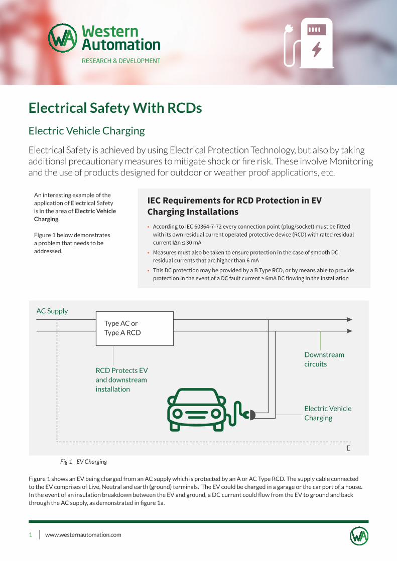
Figure 1 shows an EV being charged from an AC supply which is protected by an A or AC Type RCD. The supply cable connected to the EV comprises of Live, Neutral and earth (ground) terminals. The EV could be charged in a garage or the car port of a house. In the event of an insulation breakdown between the EV and ground, a DC current could fl ow from the EV to ground and back through the AC supply, as demonstrated in fi gure 1a.
Fig 1 - EV Charging
Type AC orType A RCD
RCD Protects EVand downstreaminstallation
AC Supply
Downstreamcircuits
Electric VehicleCharging
E
IEC Requirements for RCD Protection in EV Charging Installations• According to IEC 60364-7-72 every connection point (plug/socket) must be fitted
with its own residual current operated protective device (RCD) with rated residual current I∆n ≤ 30 mA
• Measures must also be taken to ensure protection in the case of smooth DC residual currents that are higher than 6 mA
• This DC protection may be provided by a B Type RCD, or by means able to provide protection in the event of a DC fault current ≥ 6mA DC flowing in the installation
www.westernautomation.com 2
Electric Vehicle Charging
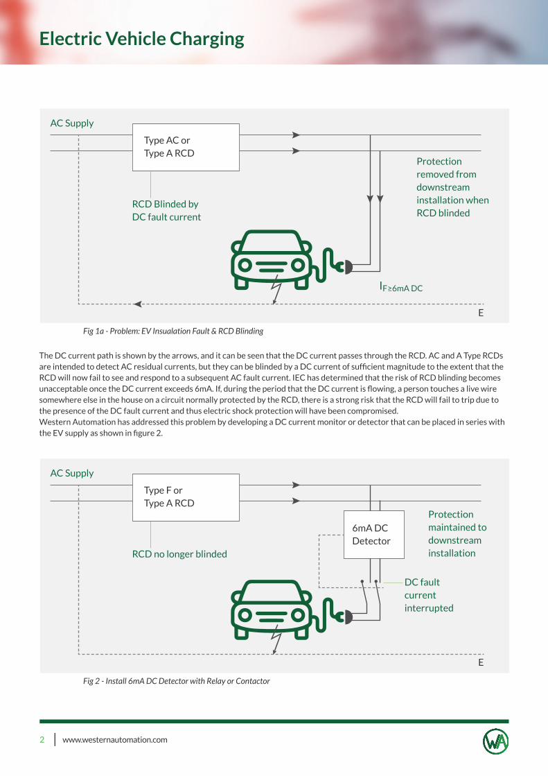
The DC current path is shown by the arrows, and it can be seen that the DC current passes through the RCD. AC and A Type RCDs are intended to detect AC residual currents, but they can be blinded by a DC current of suffi cient magnitude to the extent that the RCD will now fail to see and respond to a subsequent AC fault current. IEC has determined that the risk of RCD blinding becomes unacceptable once the DC current exceeds 6mA. If, during the period that the DC current is fl owing, a person touches a live wire somewhere else in the house on a circuit normally protected by the RCD, there is a strong risk that the RCD will fail to trip due to the presence of the DC fault current and thus electric shock protection will have been compromised. Western Automation has addressed this problem by developing a DC current monitor or detector that can be placed in series with the EV supply as shown in fi gure 2.
Fig 1a - Problem: EV Insualation Fault & RCD Blinding
Fig 2 - Install 6mA DC Detector with Relay or Contactor
Type AC orType A RCD
Type F orType A RCD
6mA DCDetector
E
RCD Blinded byDC fault current
RCD no longer blinded
AC Supply
AC Supply
Protectionremoved fromdownstream installation whenRCD blinded
Protectionmaintained to downstreaminstallation
DC faultcurrent interrupted
IF≥6mA DC
E
www.westernautomation.com 3
Electrical Safety With RCDs
ST = Self Test, EOL = End Of LifeReliability & Product Failure
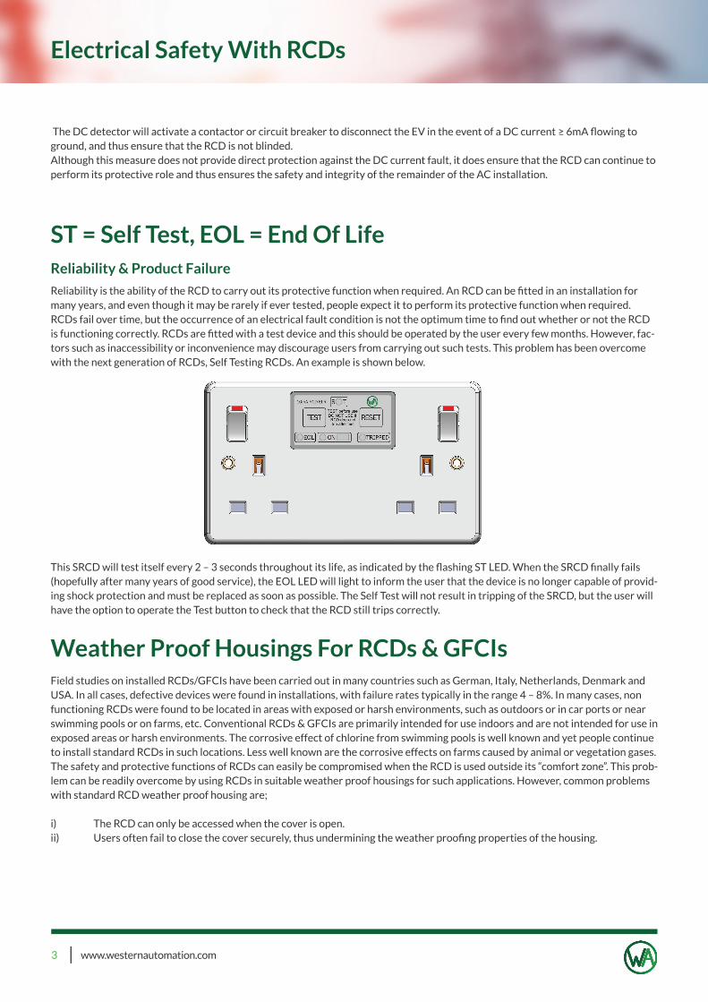
Reliability is the ability of the RCD to carry out its protective function when required. An RCD can be fi tted in an installation for many years, and even though it may be rarely if ever tested, people expect it to perform its protective function when required. RCDs fail over time, but the occurrence of an electrical fault condition is not the optimum time to fi nd out whether or not the RCD is functioning correctly. RCDs are fi tted with a test device and this should be operated by the user every few months. However, fac-tors such as inaccessibility or inconvenience may discourage users from carrying out such tests. This problem has been overcome with the next generation of RCDs, Self Testing RCDs. An example is shown below.
This SRCD will test itself every 2 – 3 seconds throughout its life, as indicated by the fl ashing ST LED. When the SRCD fi nally fails (hopefully after many years of good service), the EOL LED will light to inform the user that the device is no longer capable of provid-ing shock protection and must be replaced as soon as possible. The Self Test will not result in tripping of the SRCD, but the user will have the option to operate the Test button to check that the RCD still trips correctly.
Weather Proof Housings For RCDs & GFCIsField studies on installed RCDs/GFCIs have been carried out in many countries such as German, Italy, Netherlands, Denmark and USA. In all cases, defective devices were found in installations, with failure rates typically in the range 4 – 8%. In many cases, non functioning RCDs were found to be located in areas with exposed or harsh environments, such as outdoors or in car ports or near swimming pools or on farms, etc. Conventional RCDs & GFCIs are primarily intended for use indoors and are not intended for use in exposed areas or harsh environments. The corrosive effect of chlorine from swimming pools is well known and yet people continue to install standard RCDs in such locations. Less well known are the corrosive effects on farms caused by animal or vegetation gases. The safety and protective functions of RCDs can easily be compromised when the RCD is used outside its “comfort zone”. This prob-lem can be readily overcome by using RCDs in suitable weather proof housings for such applications. However, common problems with standard RCD weather proof housing are;
i) The RCD can only be accessed when the cover is open.ii) Users often fail to close the cover securely, thus undermining the weather proofi ng properties of the housing.
The DC detector will activate a contactor or circuit breaker to disconnect the EV in the event of a DC current ≥ 6mA fl owing to ground, and thus ensure that the RCD is not blinded. Although this measure does not provide direct protection against the DC current fault, it does ensure that the RCD can continue to perform its protective role and thus ensures the safety and integrity of the remainder of the AC installation.
www.westernautomation.com 4
Electrical Safety With RCDs
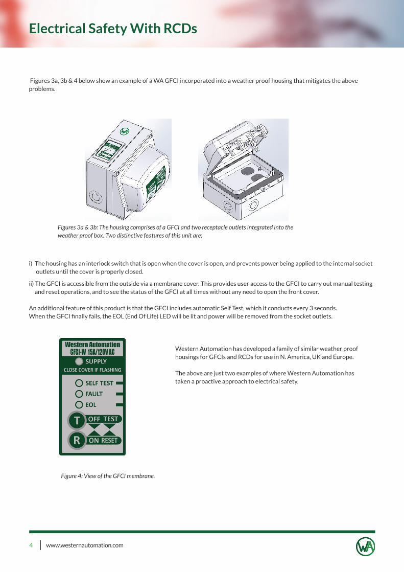
Figures 3a, 3b & 4 below show an example of a WA GFCI incorporated into a weather proof housing that mitigates the above problems.
i) The housing has an interlock switch that is open when the cover is open, and prevents power being applied to the internal socket outlets until the cover is properly closed.
ii) The GFCI is accessible from the outside via a membrane cover. This provides user access to the GFCI to carry out manual testing and reset operations, and to see the status of the GFCI at all times without any need to open the front cover.
An additional feature of this product is that the GFCI includes automatic Self Test, which it conducts every 3 seconds. When the GFCI fi nally fails, the EOL (End Of Life) LED will be lit and power will be removed from the socket outlets.
Western Automation has developed a family of similar weather proof housings for GFCIs and RCDs for use in N. America, UK and Europe.
The above are just two examples of where Western Automation has taken a proactive approach to electrical safety.
Figures 3a & 3b: The housing comprises of a GFCI and two receptacle outlets integrated into the weather proof box. Two distinctive features of this unit are;
Figure 4: View of the GFCI membrane.