electrical systems - brunswick marine in...
TRANSCRIPT

4
E
ELECTRICAL SYSTEMS
WIRING DIAGRAMS
Note:Refer to the following Service Bulletin regarding this section.
SB 96-2 Water In Fuel Module (WIF) Warning Light

4E -0 - WIRING DIAGRAMS 90-806934 1194
Table of ContentsPage
Wiring Colors for MerCruiser Diesel 4E -1. . . . . . . . . . . . . Wire Color Abbreviations 4E -1. . . . . . . . . . . . . . . . . . . . . . Engine Wiring Diagrams 4E -2. . . . . . . . . . . . . . . . . . . . . . .
MCM - D3.0L/150, D3.6L/180 and D4.2L/220 - Mando Alternator 4E -2. . . . . . . . . . . MCM - D3.0L/150, D3.6L/180 and D4.2L/220 - Prestolite Alternator 4E -3. . . . . . . . . MIE - D3.0L/150, D3.6L/180 and D4.2L/220 - Mando Alternator 4E -4. . . . . . . . . . . . . . . . . . . . . . . . MIE - D3.0L/150, D3.6L/180 and D4.2L/220 - Prestolite Alternator 4E -5. . . . . . . . . . . . . . . . . . . . . .
Quicksilver Instrumentation 4E -6. . . . . . . . . . . . . . . . . . . . MCM - D3.0L/150, D3.6L/150 and D4.2L/220 4E -6. . MIE - D3.0L/150, D3.6L/180 and D4.2L/220 4E -7. . . MCM - Second Station Instrumentation 4E -8. . . . . . . MIE - Second Station Instrumentation 4E -9. . . . . . . .
Wiring Harness ConnectionsMCM - (Standard) 4E -10. . . . . . . . . . . . . . . . . . . . . . . . MCM - (Optional) 4E -11. . . . . . . . . . . . . . . . . . . . . . . . MIE 4E -12. . . . . . . . . . . . . . . . . . . . . . . . . . . . . . . . . . . . .
NOTE: If using other than Quicksilver instrumenta-tion and harnesses, refer to manufacturers’ instruc-tions.
4E - WIRING DIAGRAMS

WIRING DIAGRAMS - 4E -190-806934 1194
Wiring Colors for MerCruiser DieselWhere Used
Color CodePrimary Usage Secondary Usage
Black All Grounds
Black/Yellow Engine Stop
Blue Instrument Lighting
Blue/Black Glow Plug Wait Switch
Blue/Tan Glow Plug Wait Lamp
Blue/White Glow Plugs
Brown Alternator Charge Lamp Reference Electrode-MerCathode
Brown/White Trim Sender to Trim Gauge
Gray Tachometer Signal
Green Glow Plug Temperature Sensor
Green/White Trim -“Down” Switch
Lt. Blue Oil Pressure Sender to Gauge
Lt. Blue/White Trim- “Up” Switch
Orange Alternator DC Output Anode Electrode-MerCathode
Pink Fuel Gauge Sender to Gauge
Purple Ignition Switch (+12 V)
Purple/White Trim-“Trailer” Switch
Red Unprotected Wires from Battery
Red/Purple Protected (Fused) Wires from Battery Protected (+ 12V) to Trim Panel
Tan Water Temperature Sender to Gauge
Tan/Black Water Temperature Switch Transmission Fluid Temperature Switch
Tan/Blue OIl / Water Alarms
Tan/White Oil Pressure Switch Drive Oil Level Switch
White/Green Spare
Yellow/Black Transmission Neutral Safety Switch
Yellow/Red Starter Switch to Starter Solenoid toNeutral Start Switch
Wire Color AbbreviationsBLK Black RED Red
BLU Blue TAN Tan
BRN Brown WHT White
GRY Gray YEL Yellow
GRN Green LIT or LT Light
ORN Orange DRK Dark
PNK Pink
PUR or PPL Purple

See NOTE 4. BLK = BLACKBLU = BLUEBRN = BROWNGRY = GRAYGRN = GREENORN = ORANGEPPL = PURPLERED = REDTAN = TANWHT = WHITEYEL = YELLOWLT = LIGHTDRK = DARK
BLK/YEL (1)
NOT USED
NOT USED
WHT/GRN (5)
BLU/TAN (2)
TAN/BLK (3)
BRN (4)
1 - MerCathode Controller Negative (–) Connection
2 - Trim Sender3 - Water Temperature Sender/Audio
Warning Switch4 - Starter5 - Oil Pressure Switch (Audio Warning)6 - Oil Pressure Sender7 - Tachometer Magnetic Pickup8 - Audio Warning Delay Relay9 - Power Relay10- Start Relay11- Pre-Glow Relay12- 60 Amp Circuit Breaker13- 60 Amp Circuit Breaker14- Gear Lube Monitor Bottle15- Engine Ground [Negative (–)]16- Fuel Injection Pump17- Glow Plugs 18- Fuel Solenoid19- Alternator - Mando20- Battery
NOT USEDYEL/RED (7)
LT BLU (8)
BLK (1)
GRY (2)
BRN/WHT (10)
TAN (3)
TAN/BLU (4)PPL (5)
RED/PPL (6)
NOT USED
��
�
�
��
�
�
�
�� ����
��
��
1
23 4 5
67
12
4
3
56
7
8
10
See NOTE 1.
See NOTE 2.
�
��
See NOTE 3.
��
Electrical Box
�
74420
�� See NOTE 5.
NOTE 1 : Wires - Not Used On MCM EnginesNOTE 2 : Spare Wire - Not UsedNOTE 3 : Connect wires together with screw and hex nut; apply liquid neoprene to connec-tion and slide rubber sleeve over connection.NOTE 4 : Items not present on 5-Cylinder models.NOTE 5 : GRAY wire may be connected to alternator “P” terminal for tachometer signal. If con-nected in this manner, the GRAY and BLACK wire terminal ends at the Magnetic Pickup (Item 7)MUST be disconnected and protected with at least two layers of electrical tape.
AB
AB
4E -2 - WIRING DIAGRAMS 90-806934 1194
Engine Wiring Diagrams
MCM - D3.0L/150, D3.6L/180 and D4.2L/220 - Mando Alternator

74297
BLK = BLACKBLU = BLUEBRN = BROWNGRY = GRAYGRN = GREENORN = ORANGEPPL = PURPLERED = REDTAN = TANWHT = WHITEYEL = YELLOWLT = LIGHTDRK = DARK
BLK/YEL (1)
NOT USED
NOT USED
WHT/GRN (5)
BLU/TAN (2)
TAN/BLK (3)
BRN (4)
1 - MerCathode Controller Negative (–) Connection
2 - Trim Sender3 - Water Temperature Sender/Audio
Warning Switch4 - Starter5 - Oil Pressure Switch (Audio Warning)6 - Oil Pressure Sender7 - Tachometer Magnetic Pickup8 - Audio Warning Delay Relay9 - Power Relay10- Start Relay11- Pre-Glow Relay12- 60 Amp Circuit Breaker13- 60 Amp Circuit Breaker14- Gear Lube Monitor Bottle (Two Styles)15- Engine Ground [Negative (–)]16- Fuel Injection Pump17- Glow Plugs 18- Fuel Solenoid19- Alternator - Prestolite20- Battery
NOT USEDYEL/RED (7)
LT BLU (8)
BLK (1)
GRY (2)
BRN/WHT (10)
TAN (3)
TAN/BLU (4)PPL (5)
RED/PPL (6)
NOT USED
��
�
�
��
�
�
�
�� ��
��
��
��
1
23 4 5
67
12
4
3
56
7
8
10
See NOTE 1.
See NOTE 2.
�
��
See NOTE 3.
��
Electrical Box
�
BA
AB
See
NO
TE
5.
NOTE 1 : Wires - Not Used On MCM EnginesNOTE 2 : Spare Wire – Not UsedNOTE 3 : Connect wires together with screw and hex nut; apply liquid neoprene to connectionand slide rubber sleeve over connection.NOTE 4 : Items not present on 5-Cylinder models.NOTE 5: GRAY wire may be connected to alternator “AC” terminal for tachometer signal. If con-nected in this manner, the GRAY and BLACK wire terminal ends at the Magnetic Pickup (Item 7)MUST be disconnected and protected with at least two layers of electrical tape.
See NOTE 4.
��
��
WIRING DIAGRAMS - 4E -390-806934 1194
MCM - D3.0L/150, D3.6L/180 and D4.2L/220 - Prestolite Alternator

4E -4 - WIRING DIAGRAMS 90-806934 1194
MIE - D3.0L/150, D3.6L/180 andD4.2L/220 - Mando Alternator
74432
BLK = BLACKBLU = BLUEBRN = BROWNGRY = GRAYGRN = GREENORN = ORANGEPPL = PURPLERED = REDTAN = TANWHT = WHITEYEL = YELLOWLT = LIGHTDRK = DARK
BLK/YEL (1)
NOT USED
NOT USED
WHT/GRN (5)
BLU/TAN (2)
TAN/BLK (3)
BRN (4)
1 - Water Temperature Sender/Audio Warning Switch
2 - Transmission Fluid Temperature Audio Warning Switch
3 - Transmission Neutral Safety Start Switch4 - Starter5 - Oil Pressure Switch (Audio Warning)6 - Oil Pressure Sender7 - Tachometer Magnetic Pickup8 - Audio Warning Delay Relay9 - Power Relay10- Start Relay11- Pre-Glow Relay12- 60 Amp Circuit Breaker13- 60 Amp Circuit Breaker14- Wires Not Used on MIE Engines15- Engine Ground [Negative (–)]16- Fuel Injection Pump17- Glow Plugs 18- Fuel Solenoid19- Alternator - Mando20- Battery
NOTE 1 : Wires - Not Used On MIE EnginesNOTE 2 : Spare Wire – Not UsedNOTE 3 : Items not present on 5 cylinder models.
NOT USEDYEL/RED (7)
LT BLU (8)
BLK (1)
GRY (2)
BRN/WHT (10)
TAN (3)
TAN/BLU (4)PPL (5)
RED/PPL (6)
NOT USED
�
�
��
��
�
�
�
�� ��
��
��
��
1
23 4 5
67
12
4
3
56
7
8
10
�
��
��
��
Electrical Box
See NOTE 1.
See NOTE 1.
See NOTE 2.
See NOTE 3.
NOTE 4 : GRAY wire may be connected to alternator “P” terminal for tachometer signal. Ifconnected in this manner, the GRAY and BLACK wire terminal ends at the Magnetic Pickup(Item 7) MUST be disconnected and protected with at least two layers of electrical tape.
See NOTE 4.
AB
AB

74327
BLK = BLACKBLU = BLUEBRN = BROWNGRY = GRAYGRN = GREENORN = ORANGEPPL = PURPLERED = REDTAN = TANWHT = WHITEYEL = YELLOWLT = LIGHTDRK = DARK
BLK/YEL (1)
NOT USED
NOT USED
WHT/GRN (5)
BLU/TAN (2)
TAN/BLK (3)
BRN (4)
1 - Water Temperature Sender/Audio Warning Switch
2 - Transmission Fluid Temperature Audio Warning Switch
3 - Transmission Neutral Safety Start Switch4 - Starter5 - Oil Pressure Switch (Audio Warning)6 - Oil Pressure Sender7 - Tachometer Magnetic Pickup8 - Audio Warning Delay Relay9 - Power Relay10- Start Relay11- Pre-Glow Relay12- 60 Amp Circuit Breaker13- 60 Amp Circuit Breaker14- Engine Ground [Negative (–)]15- Fuel Injection Pump16- Glow Plugs17- Fuel Solenoid18- Alternator – Prestolite19- Battery
NOTE 1 : Wires - Not Used On MIE EnginesNOTE 2 : Spare Wire – Not UsedNOTE 3 : Items Not Present On 5 Cylinder Engines
NOT USEDYEL/RED (7)
LT BLU (8)
BLK (1)
GRY (2)
BRN/WHT (10)
TAN (3)
TAN/BLU (4)PPL (5)
RED/PPL (6)
NOT USED
�
�
�
�
��
�
�
�
�� ��
��
��
1
23 4 5
67
12
4
3
56
7
8
10
�
��
��
Electrical Box
See NOTE 1.
See NOTE 1.
See NOTE 2.
A
A
B
B
��
See
NO
TE
1.
NOTE 4 : GRAY wire may be connected to alternator “AC” terminal for tachometer signal. Ifconnected in this manner, the GRAY and BLACK wire terminal ends at the Magnetic Pickup(Item 7) MUST be disconnected and protected with at least two layers of electrical tape.
See
NO
TE
4.
See NOTE 3.
��
WIRING DIAGRAMS - 4E -590-806934 1194
MIE - D3.0L/150, D3.6L/180 and D4.2L/220 - Prestolite Alternator

A B
1 - Oil Pressure2 - Tachometer3 - Trim Gauge 4 - Coolant Temperature5 - Voltmeter6 - Cruise Log (Engine Hour Meter) (See NOTE 1.)7 - Engine System Monitor -
a.-PreHeat, b.-Alternator,c.-Oil Pressure, d.-Coolant Temp.
12
34
56
7
8
1 2
4
3
56
7
8
10
YEL/RED (7)
LT BLU (8)
BLK (1)
GRY (2)
BRN/WHT (10)
TAN (3)
TAN/BLU (4)
PPL (5)RED/PPL (6)
BLK/YEL (1)
BLK (8)
BLK (7)TAN/WHT (6)
WHT/GRN (5)
BLU/TAN (2)TAN/BLK (3)
BRN (4)
�
�
�
�
�
�
�
74066
NOTE 2: Connect wires together with screw and hex nut;apply Liquid Neoprene to connection and slide rubber sleeveover connection.
See NOTE 2.
�� ��
��
��
��
8 - Light Switch and Audio Test9 - Stop Switch10- Keyswitch11- 20-Amp Fuse and Holder12- Audio Warning Buzzers13- Spare Wires - (Not Used) 14- Remote Control -
(Neutral Safety Circuit)
NOTE 1: May be wired to any PPL (that is key switched),and BLK.
�
�
BLK = BLACKBLU = BLUEBRN = BROWNGRY = GRAYGRN = GREENORN = ORANGEPPL = PURPLERED = REDTAN = TANWHT = WHITEYEL = YELLOWLT = LIGHTDRK = DARK
UP
BS
I
b
c
d
a
A B
4E -6 - WIRING DIAGRAMS 90-806934 1194
Quicksilver Instrumentation
MCM - D3.0L/150, D3.6L/150 and D4.2L/220

1 - Oil Pressure2 - Tachometer3 - Wires Not Used
(See NOTE 1.)4 - Coolant Temperature5 - Voltmeter6 - Cruise Log (Engine Hour Meter) (See NOTE 2.)7 - Engine System Monitor -
a.-PreHeat, b.-Alternator,c.-Oil Pressure, d.-Coolant Temp.
12
34
56
7
8
1 2
4
3
56
7
8
10
YEL/RED (7)
LT BLU (8)
BLK (1)
GRY (2)
BRN/WHT (10)
TAN (3)
TAN/BLU (4)
PPL (5)RED/PPL (6)
BLK/YEL (1)
BLK (8)
BLK (7)TAN/WHT (6)
WHT/GRN (5)
BLU/TAN (2)TAN/BLK (3)
BRN (4)
�
�
�
�
�
�
73603
�� ��
��
��
8 - Light Switch and Audio Test9 - Stop Switch10- Keyswitch11- 20-Amp Fuse and Holder12- Audio Warning Buzzers13- Spare Wires - (Not Used)
NOTE 1 : Tape each wire separately with at least two layers of elec-trical tape.NOTE 2 : May be wired to any PPL (that is key switched), and BLK.
�
�
BLK = BLACKBLU = BLUEBRN = BROWNGRY = GRAYGRN = GREENORN = ORANGEPPL = PURPLE
RED = REDTAN = TANWHT = WHITEYEL = YELLOWLT = LIGHTDRK = DARK
�
UP
b
c
d
a
A B
A B
WIRING DIAGRAMS - 4E -790-806934 1194
MIE - D3.0L/150, D3.6L/180 andD4.2L/220
12
34
56
7
8
1 2
4
3
56
7
8
10
a b
With Remote Control Neutral Safety Switch Wired at Instrumentation
YEL/RED (7)
LT BLU (8)
BLK (1)
GRY (2)
BRN/WHT (10)
TAN (3)
TAN/BLU (4)
PPL (5)RED/PPL (6)
a
BLK/YEL (1)
BLK (8)
BLK (7)TAN/WHT (6)
WHT/GRN (5)
BLU/TAN (2)TAN/BLK (3)
BRN (4)
b
74065
See NOTE 2.
BLK = BLACKBLU = BLUEBRN = BROWNGRY = GRAYGRN = GREENORN = ORANGEPPL = PURPLE
RED = REDTAN = TANWHT = WHITEYEL = YELLOWLT = LIGHTDRK = DARK
UP
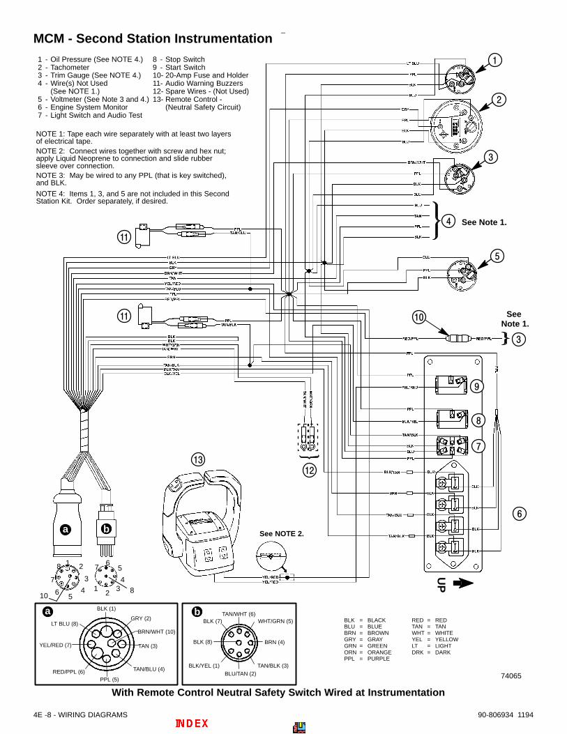
1 - Oil Pressure (See NOTE 4.)2 - Tachometer3 - Trim Gauge (See NOTE 4.)4 - Wire(s) Not Used
(See NOTE 1.) 5 - Voltmeter (See Note 3 and 4.)6 - Engine System Monitor7 - Light Switch and Audio Test
8 - Stop Switch9 - Start Switch10- 20-Amp Fuse and Holder11- Audio Warning Buzzers12- Spare Wires - (Not Used) 13- Remote Control -
(Neutral Safety Circuit)
�
�
�
NOTE 2: Connect wires together with screw and hex nut;apply Liquid Neoprene to connection and slide rubbersleeve over connection.
NOTE 1: Tape each wire separately with at least two layersof electrical tape.
See Note 1.
�
NOTE 3: May be wired to any PPL (that is key switched),and BLK.
NOTE 4: Items 1, 3, and 5 are not included in this SecondStation Kit. Order separately, if desired.
�
�
�
�
�
��
See Note 1.
��
��
���
4E -8 - WIRING DIAGRAMS 90-806934 1194
MCM - Second Station Instrumentation

WIRING DIAGRAMS - 4E -990-806934 1194
MIE - Second Station Instrumentation
74067
YEL/RED (7)
LT BLU (8)
BLK (1)
GRY (2)
BRN/WHT (10)
TAN (3)
TAN/BLU (4)
PPL (5)RED/PPL (6)
a
BLK/YEL (1)
BLK (8)
BLK (7)TAN/WHT (6)
WHT/GRN (5)
BLU/TAN (2)TAN/BLK (3)
BRN (4)
bBLK = BLACKBLU = BLUEBRN = BROWNGRY = GRAYGRN = GREENORN = ORANGEPPL = PURPLE
RED = REDTAN = TANWHT = WHITEYEL = YELLOWLT = LIGHTDRK = DARK
UP
�
�
��
�
�
12
34
56
7
8
1 2
4
3
56
7
8
10
a b
� See Note 1.
�
�
�
See Note 1.
1 - Oil Pressure(See NOTE 4.)
2 - Tachometer3 - Wire(s) Not Used
(See NOTE 1.) 4 - Voltmeter
(See NOTE 4.)
5 - Engine System Monitor6 - Light Switch and Audio Test7 - Stop Switch8 - Start Switch9 - 20-Amp Fuse and Holder10- Audio Warning Buzzers11- Spare Wires - (Not Used)
NOTE 2: Connect wires together with screw and hex nut;apply Liquid Neoprene to connection and slide rubbersleeve over connection.
NOTE 1: Tape each wire separately with at least two layersof electrical tape.
NOTE 3: May be wired to any PPL (that is key switched),and BLK.
NOTE 4: Items 1 and 4 are not included in this Second Sta-tion Kit. Order separately, if desired.
�
See Note 1.
�
�
�

MCM - With Remote Control Neutral Safety Switches Wired at Instrumentation
a - “Y” Harnessb - “T” Harnessc - Extension Harnesses (Primary to Secondary Instrumentation)d - Extension Harnesses (To Engine)
Note: Connect these wires together with a screw andnut. Coat with Liquid Neoprene and slide rubber sleeveover connection.
See Note.
See Note.
Primary StationSecondary Station
d
ba
c
74069
4E -10 - WIRING DIAGRAMS 90-806934 1194
Wiring Harness ConnectionsMCM - Wiring Harness Connections (Standard)

MCM - With Remote Control Neutral Safety Switches Wired at Harnesses
a - “Y” Harnessb - “T” Harnessc - Extension Harnesses (Primary to Secondary Instrumentation)d - Extension Harnesses (To Engine)
Note: Connect these wires together with a screw andnut. Coat with Liquid Neoprene and slide rubber sleeveover connection.
d
b
See
No
te:
See
No
te:
a
c
Primary StationSecondary Station
74068
WIRING DIAGRAMS - 4E -1190-806934 1194
MCM - Wiring Harness Connections (Optional)

MIE - Harnesses
a - “Y” Harnessb - “T” Harnessc - Extension Harnesses (Primary to Secondary Instrumentation)d - Extension Harnesses (To Engine)
Note: Connect these wires together with a screw andnut. Coat with Liquid Neoprene and slide rubber sleeveover connection.
See Note.
See Note.
d
ba
c
Primary StationSecondary Station
74070
4E -12 - WIRING DIAGRAMS 90-806934 1194
MIE - Wiring Harness Connections