electrical technology feb-march 2010 eng
TRANSCRIPT

7/28/2019 Electrical Technology Feb-March 2010 Eng
http://slidepdf.com/reader/full/electrical-technology-feb-march-2010-eng 1/14
MARKS: 200
TIME: 3 hours
This question paper consists of 13 pages and 1 formula sheet.
Copyright reserved Please turn over
ELECTRICAL TECHNOLOGY
FEBRUARY/MARCH 2010
NATIONALSENIOR CERTIFICATE
GRADE 12

7/28/2019 Electrical Technology Feb-March 2010 Eng
http://slidepdf.com/reader/full/electrical-technology-feb-march-2010-eng 2/14
Electrical Technology 2 DoE/Feb. – March 2010NSC
Copyright reserved Please turn over
INSTRUCTIONS AND INFORMATION
1.
2.
3.
4.
5.
6.
This question paper consists of TEN questions. Answer ALL the questions.
Sketches and diagrams must be large, neat and fully labelled.
All calculations must be shown and correctly rounded off to TWO decimalplaces.
Number the answers correctly according to the numbering system used in thisquestion paper.
A formula sheet is provided at the end of the question paper.
Non-programmable calculators may be used.

7/28/2019 Electrical Technology Feb-March 2010 Eng
http://slidepdf.com/reader/full/electrical-technology-feb-march-2010-eng 3/14
Electrical Technology 3 DoE/Feb. – March 2010NSC
Copyright reserved Please turn over
QUESTION 1: TECHNOLOGY, SOCIETY AND THE ENVIRONMENT
1.1 Sewage treatment facilities rely on different stages during the filtering andcleansing process. Huge volumes of water are pumped from stage to stage
and oxygen is added to the water to kill pathogens.
FIGURE 1.1: SEWAGE TREATMENT PROCESS
Sewage treatment plants in various areas of South Africa are failing, and as aresult our rivers are being polluted with raw sewage. This has caused choleraoutbreaks in some parts of South Africa and in Zimbabwe cholera has alreadyclaimed thousands of lives.
In what way, do you think, has electrical technology, or the misappropriationthereof, contributed to the non-treatment of sewage in South Africa? Nameand discuss TWO issues. (4)
1.2 HIV/Aids is an incurable disease. In the medical industry, electricaltechnology is used in various diagnostic medical instruments. How, do you
think, can electrical technology contribute positively towards the treatment of HIV and Aids? (2)
1.3 Name TWO recent advancements in electrical technology and state how theyhave had an effect on society. (4)
[10]

7/28/2019 Electrical Technology Feb-March 2010 Eng
http://slidepdf.com/reader/full/electrical-technology-feb-march-2010-eng 4/14
Electrical Technology 4 DoE/Feb. – March 2010NSC
Copyright reserved Please turn over
QUESTION 2: TECHNOLOGICAL PROCESS
Read the scenario below and answer the questions that follow.
Sibusiso decided to improve the security of his room at home, since someone couldenter the room without his permission. He went out to the spaza shop and boughtmousetraps to place at his door when he was away. His uncle told him the best way tocatch a rat is with a mousetrap. This way the intruder would get a painful sting whenthe mousetrap is triggered and the problem would be solved.
Sibusiso was sure that his invention would work well and did not mind paying R400,00for the mousetraps.
2.1
2.2
2.3
2.4
Do you think Sibusiso's invention can work? Motivate your answer.
Do you think Sibusiso's uncle gave him good advice? Motivate your answer.
What process would you suggest should Sibusiso follow to arrive at a solutionthat relies on electrical technology? List FOUR steps.
State any TWO criteria that you think Sibusiso might be able to use to choosethe best solution for his problem.
(2)
(2)
(4)
(2)[10]

7/28/2019 Electrical Technology Feb-March 2010 Eng
http://slidepdf.com/reader/full/electrical-technology-feb-march-2010-eng 5/14
Electrical Technology 5 DoE/Feb. – March 2010NSC
Copyright reserved Please turn over
QUESTION 3: OCCUPATIONAL HEALTH AND SAFETY
3.1
3.2
State TWO precautions that must be taken when measuring the current flowin a circuit with a digital multimeter.
State TWO precautions that must be taken when using a grinding machine.
(2)
(2)
3.3
3.4
3.5
Describe why it is important to have good ventilation in an electricaltechnology workshop.
State TWO unsafe actions that can occur in an electrical technologyworkshop.
Describe ONE precaution to be taken when stripping off the insulation of aconductor.
(2)
(2)
(2)
[10]
QUESTION 4: THREE-PHASE AC GENERATION
4.1
4.2
4.3
4.4
4.5
State how the power factor of a resistive inductive load may be improved.
Name TWO advantages of a three-phase system over a single-phase system. Define the term balanced load.
Describe ONE disadvantage of a three-phase motor that has a poor laggingpower factor.
A 2,5 kW balanced load is connected in delta to a 380 V supply. The loadhas a power factor of 0,85 and a rendement of 100%. Calculate the kVArating of the load at full load.
(1)
(2)
(2)
(2)
(3)[10]
QUESTION 5: RLC CIRCUITS
5.1
5.2
Describe ONE practical method used to determine whether an RLC series
circuit is at resonant frequency.
An incandescent lamp is connected in series with an inductor and a capacitor.Describe what will happen to the brightness of the lamp if the frequency ischanged to resonant frequency.
(3)
(3)
7/28/2019 Electrical Technology Feb-March 2010 Eng
http://slidepdf.com/reader/full/electrical-technology-feb-march-2010-eng 6/14
Electrical Technology 6 DoE/Feb. – March 2010NSC
Copyright reserved Please turn over
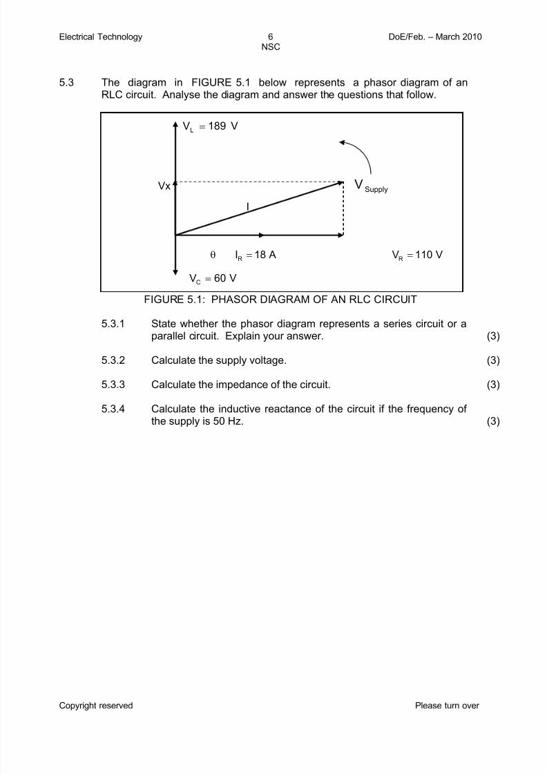
5.3 The diagram in FIGURE 5.1 below represents a phasor diagram of anRLC circuit. Analyse the diagram and answer the questions that follow.
SupplyV
V60VC =
Vx
V189VL=
I
V110V A18IRR
==θ
FIGURE 5.1: PHASOR DIAGRAM OF AN RLC CIRCUIT
5.3.1
5.3.2
5.3.3
5.3.4
State whether the phasor diagram represents a series circuit or aparallel circuit. Explain your answer.
Calculate the supply voltage.
Calculate the impedance of the circuit.
Calculate the inductive reactance of the circuit if the frequency of the supply is 50 Hz.
(3)
(3)
(3)
(3)

7/28/2019 Electrical Technology Feb-March 2010 Eng
http://slidepdf.com/reader/full/electrical-technology-feb-march-2010-eng 7/14
Electrical Technology 7 DoE/Feb. – March 2010NSC
Copyright reserved Please turn over
5.4 A resistor with a resistance of 39 Ω, a capacitor with a capacitive reactance of 50 Ω and an inductor with an inductive reactance of 75 Ω are all connected inparallel across a 240 V/50 Hz supply.
FIGURE 5.2: RLC CIRCUIT
Calculate the following:
5.4.1
5.4.2
5.4.3
5.4.4
The current through the resistor
The current through the inductor
The current through the capacitor
The supply current
(3)
(3)
(3)
(3)[30]
QUESTION 6: SWITCHING AND CONTROL CIRCUITS
6.1
6.2
Draw a fully labelled circuit symbol of an SCR.
Explain how an SCR can be switched on and also how it can be switched off.
(3)
(4)

7/28/2019 Electrical Technology Feb-March 2010 Eng
http://slidepdf.com/reader/full/electrical-technology-feb-march-2010-eng 8/14
Electrical Technology 8 DoE/Feb. – March 2010NSC
Copyright reserved Please turn over
6.3 The circuit shown in FIGURE 6.1 below uses a DIAC and a TRIAC to controlthe brightness of a lamp. The circuit is connected to a 220 V/50 Hz supply.Explain the operation of the circuit.
FIGURE 6.1: LAMP-DIMMING CIRCUIT (9)
10 K
220 V AC50 Hz
0,1μF
C1200 W load
6.4
6.5
State whether the voltage developed across the TRIAC in FIGURE 6.1 ishigh or low when current is flowing in the circuit.
The DIAC in FIGURE 6.1 triggers the TRIAC at 90° in the first half-cycle andagain at 270° in the second half-cycle.
(1)
6.5.1
6.5.2
Draw the input voltage wave form and the voltage wave formacross the lamp on the same set of axes.
Compared to the full brightness of the lamp, state the expectedbrightness of the lamp. Give a reason for your answer.
(5)
(3)[25]
QUESTION 7: AMPLIFIERS
7.1
7.2
7.3
Name the THREE major classes of power audio amplifiers.
Draw a block diagram of a basic amplifier showing the input and outputsignals.
With reference to feedback in amplifiers, answer the following questions:
(3)
(4)
7.3.1
7.3.2
Name TWO advantages of using negative feedback in amplifier circuits.
Draw an operational amplifier in the configuration of an invertingvoltage comparator.
(2)
(5)
7.4 Describe the TWO requirements for oscillation to occur in all oscillators. (4)

7/28/2019 Electrical Technology Feb-March 2010 Eng
http://slidepdf.com/reader/full/electrical-technology-feb-march-2010-eng 9/14
Electrical Technology 9 DoE/Feb. – March 2010NSC
Copyright reserved Please turn over
7.5 With reference to the amplifier in FIGURE 7.1 below, answer the questionsthat follow.
FIGURE 7.1: AMPLIFIER
+15 V
Input 1
Input 2
-15 V
7.5.1
7.5.2
Name the mode of operation of this circuit.
Draw the input and output signals of this circuit.
(1)
(3)
7.6 Calculate the oscillation frequency of an LC oscillator when the tank circuithas an inductance L = 10 mH and a capacitance C = 220 µF. (3)
[25]
QUESTION 8: THREE-PHASE TRANSFORMERS
8.1 Name the most common application of a transformer with the followingconfigurations in the mains power distribution grid:
8.1.1
8.1.2
8.1.3
Star-star
Delta-star
Star-delta
(1)
(1)
(1)
8.2 The transformer supplying Mamellong Comprehensive School with power isconnected in delta to an 11 kV supply. The secondary side supplies theschool with a three-phase four-wire system. The school receives a single-phase voltage of 220 V and three-phase line voltage of 380 V from thetransformer.
8.2.1 Show, by means of a simple diagram, how the secondary side of the transformer is connected to the school. (5)

7/28/2019 Electrical Technology Feb-March 2010 Eng
http://slidepdf.com/reader/full/electrical-technology-feb-march-2010-eng 10/14

7/28/2019 Electrical Technology Feb-March 2010 Eng
http://slidepdf.com/reader/full/electrical-technology-feb-march-2010-eng 11/14
Electrical Technology 11 DoE/Feb. – March 2010NSC
Copyright reserved Please turn over
9.2 Referring to FIGURE 9.2 below, answer the following questions:
L1
FIGURE 9.2: ELECTRICAL CIRCUIT
9.2.1
9.2.2
9.2.3
Draw the symbol of the logic gate represented by the circuit inFIGURE 9.2.
Draw the truth table of the gate.
Draw the ladder diagram of the gate.
(2)
(4)
(3)
9.3 Determine the Boolean equation of the logic circuit in FIGURE 9.3 below.Ignore the zero indicators at the gates, as this indicates an idle state.
&
&
1
FIGURE 9.3: LOGIC CIRCUIT (3)

7/28/2019 Electrical Technology Feb-March 2010 Eng
http://slidepdf.com/reader/full/electrical-technology-feb-march-2010-eng 12/14
Electrical Technology 12 DoE/Feb. – March 2010NSC
Copyright reserved Please turn over
A'B'
9.4 In the following Boolean equation, prove that the left-hand side is equal to the
right-hand side:
(A + B) . (A + C) = A + BC (4)
9.5 Determine the equation that is represented by the plotted Karnaugh mapshown in FIGURE 9.4 below.
A'B AB AB' B A B A B A AB 00 01 1011
C C 0 1 1 1
C' C 1 1 11
FIGURE 9.4: KARNAUGH MAP (6)
9.6 Explain the difference between synchronous and asynchronous counters byreferring to clock pulses. (4)
[35]

7/28/2019 Electrical Technology Feb-March 2010 Eng
http://slidepdf.com/reader/full/electrical-technology-feb-march-2010-eng 13/14
Electrical Technology 13 DoE/Feb. – March 2010NSC
Copyright reserved
QUESTION 10: THREE-PHASE MOTORS AND CONTROL
10.1
10.2
10.3
Explain why the casing of a three-phase motor must be earthed.
State how the direction of rotation of a three-phase induction motor may bereversed.
The circuit in FIGURE 10.1 below is the control circuit of a star-delta starter.
(2)
(2)
FIGURE 10.1: STAR-DELTA CONTROL CIRCUIT
10.3.1
10.3.2
10.3.3
(5)Explain the starting sequence of this starter.
Give the reasons why a star-delta starter is used to start a three-phase induction motor.
Describe ONE function of the overload switch.
(5)
(2)
10.4 Describe the term N/O with reference to electromagnetic relays. (2)
10.5
10.6
Describe the principle of operation of a three-phase induction motor.
A 5 kW motor is connected in delta to a 380 V/50 Hz supply. If the motor hasa power factor of 0,8, calculate at full load:
(6)
(3)10.6.1
10.6.2
The current drawn from the supply
The current flow in each phase (3)[30]
TOTAL: 200

7/28/2019 Electrical Technology Feb-March 2010 Eng
http://slidepdf.com/reader/full/electrical-technology-feb-march-2010-eng 14/14
Electrical Technology DoE/Feb. – March 2010NSC
Copyright reserved
FORMULA SHEET
RLC
2ππ F X L =
2ππ F
1 X
C =
2
C L
2 ) X (X R Z −+=
( )2 LC
2
RT I I I I −+=
( )2 LC
2
RT V V V V −+=
LC 2π
1 f r =
C
L
R
1Q =
R
L L
V
V
R
X Q ==
T
R
I
I Cosθ =
Z
RCosθ =
Ampl if iers
1 R
R
Avin
f
+=
b
c
I
I β =
ceb I I I −=
i
0G
P
P 10log P =
Alternating Current, Transformers and Motors
Single Φ
VIcosθ P =
VI S =
VIsinθ Q =
Three Φ
cosθ I V 3 P L L= L L I V 3S =
sinθ I V 3Q L L=
PH L I 3 I = for Δ
Ph L V V = for Δ
Ph L V 3V = for Υ
Ph L I I = for Υ
T
1 f =
1
2
2
1
2
1
I
I
N
N
V
V ==
I
O
P
P η =
(6RC)2π
1 f r =
END