electrical transport phenomena in mnte, an ... · electrical transport phenomena in mnte, an...
TRANSCRIPT
Electrical transport phenomena in MnTe, anantiferromagnetic semiconductorWasscher, J.D.
DOI:10.6100/IR43336
Published: 01/01/1969
Document VersionPublisher’s PDF, also known as Version of Record (includes final page, issue and volume numbers)
Please check the document version of this publication:
• A submitted manuscript is the author's version of the article upon submission and before peer-review. There can be important differencesbetween the submitted version and the official published version of record. People interested in the research are advised to contact theauthor for the final version of the publication, or visit the DOI to the publisher's website.• The final author version and the galley proof are versions of the publication after peer review.• The final published version features the final layout of the paper including the volume, issue and page numbers.
Link to publication
Citation for published version (APA):Wasscher, J. D. (1969). Electrical transport phenomena in MnTe, an antiferromagnetic semiconductorEindhoven: Technische Hogeschool Eindhoven DOI: 10.6100/IR43336
General rightsCopyright and moral rights for the publications made accessible in the public portal are retained by the authors and/or other copyright ownersand it is a condition of accessing publications that users recognise and abide by the legal requirements associated with these rights.
• Users may download and print one copy of any publication from the public portal for the purpose of private study or research. • You may not further distribute the material or use it for any profit-making activity or commercial gain • You may freely distribute the URL identifying the publication in the public portal ?
Take down policyIf you believe that this document breaches copyright please contact us providing details, and we will remove access to the work immediatelyand investigate your claim.
Download date: 02. Jun. 2018

ELECTRICAL TRANSPORT PHENOMENA IN MnTe,
AN ANTIFERROMAGNETIC SEMICONDUCTOR
J. D. WASSCHER
ELECTRICAL TRANSPORT PHENOMENA IN MnTe,
AN ANTIFERROMAGNETIC SEMICONDUCTOR
PROEFSCHRIFT
TER VERKRUGING VAN DE GRAAD VAN DOCTOR IN DE TECHNISCHE WETENSCHAPPEN AAN DE TECHNISCHE HOGESCHOOL TE EINDHOVEN OP GEZAG VAN DE RECTOR MAGNIFICUS PROF. DR. IR. A. A. TH. M. VAN TRIER, HOOGLERAAR IN DE AFDELING DER ELEKTROTECHNIEK, VOOR EEN COMMISSIE UIT DE SENAAT TE VERDEDIGEN OP DINSDAG 30 SEPTEMBER 1969 DES NAMIDDAGS TE 4 UUR
DOOR
JAN DOUWE WASSCHER
GEBOREN TE GRONINGEN

DIT PROEFSCHRIFT IS GOEDGEKEURD DOOR DE PROMOTOR PROF. DR. F. VAN DER MAESEN

Aan de nagedachtenis van mijn ouders

CONTENTS
INTRODUCTION . . . . . . . .
I. SOME PROPERTIES OF MnTe 4
l.I. Previous work on tbe electrical properties of MnTe 4 1.2. Pbysico-cbemical properties 5 1.3. Magnetic properties. . . . 7
2. EXPERIMENTAL METHODS 8
2.1. Experimental arrangements 8 2.1.1. Resistivity and Hall effect 8 2.1.2. Seebeck effect . . . . . 10
2.2. A method for determining tbe anisotropy of tbe resistivity . 15 2.2.1. Tbe Van der Pauw metbod . 15 2.2.2. Reetangolar samples 17 2.2.3. Circular samples . . . . 19 2.2.4. Sensitivity of tbe metbod . 22 2.2.5. Applications . . . . . . 23
3. EXPERIMENTAL RESULTS AND DISCUSSION. 25
3.1. Survey of main experimental results . . . . . . . . . . . . . 25 3.1.1. Measurements of resistivity, Hall coefficient and Seebeck
coefficient . . . . . . 25 3.1.2. Theoretical formulae . 25 3.1.3. Preliminary discussion . 30
3.2. Tbe Hall coefficient . . . . . 32 3.2.1. Furtber measurements on tbe anisotropy of R8 . 32 3.2.2. Tbe anomalous Hall effect . 33
3.3. Resistivity and Seebeck coefficient 35 3.4. The "ex perimental" mobility . . . 38 3.5. Some additional data . . . . . . 40
3.5.1. Anisotropy of tbe resistivity 40 3.5.2. Magnetoresistance . . . 41
4. SPIN-DISORDER SCATTERING. 43
4.1. Haas' tbeory of spin-disorder scattering 43 4.1.1. Tbe pbysical model . . 43 4.1.2. Tbe theoretical mobility . . . . 46 4.1.3. Additional remarks . . . . . . 49
4.2. Comparison witb tbe experimental mobility in MnTe 51

4.3. Possible irnprovements of the theory . . . . . . 52 4.3.1. Various mechanisms . . . . . . . . . . . 52 4.3.2. Magnetization-dependent band parameters . 53
4.4. Magnon scattering in antiferromagnetic semiconductors 55 4.4.1. Calculation of magnon scattering . 55 4.4.2. The condition of elastic scattering . 58
5. MAGNON DRAG. . . . . . . . . . . 60
5.1. Physical description of the drag effects 60 5.1.1. First-order effects . . 60 5.1.2. Secend-order effects . 61
5.2. Simplified theory . . . . . 61 5.2.1. Basic equations . . . 61 5.2.2. Magnon relaxation times in antiferromagnetic and ferro-
magm~tic semiconductors . . . . . . . . . . . 63 5.2.3. Magnon drag near and above the Néel temperature . 65
5.3. More accurate calculations . 66 5.4. Magnon dragin MnTe . . 69
5.4.1. General remarks . . 69 5.4.2. Drag effects at 77 °K 71 5.4.3. Drag effects near TN . 72
6. CONCLUDING REMARKS
Acknowledgement .
References
Summary
Samenvatting
78
80
81
83
85

-1
INTRODUCTION
The relation between electrical and magnetic properties ofmagnetic metals 1)
and magnetic semiconductors 2 ) is a problem with many aspects. With regard to antiferromagnetic semiconductors, investigations have been mainly restricted to transition-metal oxides (see, e.g., ref. 3). The question of the proper description of their electrical conduction has a long history and has not yet been solved.
This thesis*) is devoted to a study of the electrical properties of MnTe, which is a non-oxidic antiferromagnetic semiconductor 4 - 9 ). By suitable doping it can be made relatively low-ohmic and, in the temperature range from 77 to 500 °K, the resistivity and Seebeck coefficient (thermoelectric power) of such material increases with rising temperature. The increase is particularly marked just below 307 oK and weak above 307 °K. This behavicur is clearly connected with the magnetic properties of the compound since 307 oK is the Néel temperature, TN, of MnTe (at which a second-order phase transition occurs from the low-temperature antiferromagnetically ordered phase to the high-temperature paramagnetic phase).
Similar effects near TN appear to be absent in oxidic antiferromagnetic semiconductors. Some of these have, however, one interesting phenomenon in common with MnTe, viz. a very anomalous behaviour of the Hall coefficient at temperatures near and above TN. The effects mentioned are not due to a change in energy gap. ln MnTe the optical-energy gap is 1·2 eV both below and abme TN.
At the present moment it is difficult to evaluate the relation between the electrical properties of MnTe and those of the oxidic antiferromagnetic semiconductors. lt may be significant that the effective mass of the charge carriers is relatively low in MnTe while it is much larger in the oxides. According to Albers and Haas 10- 12) such a difference might stem from the fact that in the oxides the charge carriers occupy states of a narrow energy band derived mainly from nearly non-overlapping 3d orbitals of the transition-metal atoms, while in (p-type) MnTe the holes occupy statesof a broad energy band predominantly originating from markedly overlapping 5p Te orbitals. In addition to the low effective mass ( ~ 0·6 m0 ) another argument for a model based on broad-band conduction in p-type MnTe is the relatively high mobility of the holes (about 5 cm2/V s at TN and 100 cm2/V s at 77 °K). In this work a model of this kind will be used for the theoretica] description of the observed properties.
In two brief communications publisbed some time ago 13•14
) we have reported the results of measurements on the resistivity, Hall coefficient and
*) This work wiJl also be publisbed as Philips Res. Repts Suppl. 1969, No. 8.

-2-
Seebeck coefficient of MnTe at temperatures between 77 and 350 °K. The change in the temperature dependenee of the resistivity at TN mentioned above was attributed to spin-disorder scattering, which is known to give rise to a similar behaviour of the resistivity in ferromagnetic metals. The temperature dependenee of the Seebeck coefficient could he accounted for by magnon drag
a phenomenon similar to phonon drag in non-magnetic semiconductors -the existence of which was theoretically predicted by Bailyn 15), but which had never previously been observed (Bailyn also had ferromagnetic metals at low temperatures in mind rather than an antiferromagnetic semiconductor at TN). The anomalous behaviour of the Hall coefficient observed above 240 °K could not be explained at the time.
In the meantime the following developments have taken place. (1) The anomalous behaviour ofthe Hall coefficient was interpreted by Maranzana 16) as being due to an "extraordinary" contribution to the Hall coefficient like that found in ferromagnetic metals (as remarked above, a similar effect has now been found in the oxidicanti ferromagnetic semiconductors too 1 7
)). (2) The theoretica} mobility in magnetic semiconductors due to spin-disorder scattering was recently calculated by Haas 18). The temperature dependenee of this mobîlity is quite different from that previously assumed. (3) In conneetion with optical workon MnTe. 19) it was pointed out by Zanmarchi and Haas 20•21 ) that in consiclering magnon drag in MnTe second-order effects may have to be taken into account.
In this thesis more experimental data on the electrical properties of p-type MnTe are given than in the papers cited above 13
•14
). With respect to this earlier work the main new features of this thesis are: (I) a temperature-dependent anisotropy is found in the resistivity, indicating a temperature-dependent anisotropy in either the effective mass or the relaxation time for scattering, (2) proposals are made for extensions of Haas' theory of spin-disorder scattering, on the basis of discrepancies found in comparing the experimental data with the theory, (3) considerations involving second-order drag effects suggest that the effective mass and the acceptor-level depth may change with temperature near TN (in accordance with one of the proposed modifications of the theory).
The presentation of the various subjects is arranged as follows. In chapter I we briefly indicate the physical meaning of the transport prop
erties investigated, as well as their interpretation as given in our previous papers 13 •14). The method used for preparing MnTe is given and also some of the physico-chemical and magnetic properties of MnTe.
Chapter 2 contains a description of the experimental arrangements employed

3
for the measurements, and of a new and sensitive metbod for determining anisotropies of the resistivity.
In chapter 3 the experimental results are presented and different possibilities for their interpretation are indicated. the main difficulty here is that the anomalous behaviour of the Hall coefficient does not allow the temperature dependenee ofthe hole concentration near TN to be established unambiguously.
Chapter 4 reviews Haas' theory of spin-disorder scattering and the model on which it is based. From the discrepancy between the result of this theory and the experimental data some suggestions are made as to points in which the theory could he improved. Among these is a proposal of a model in which the band parameters (such as the effective mass) depend on the magnitude of the sublattice magnetization. In the last section of this chapter the spin-disorder mobility in antiferromagnetic semiconductors is calculated on the basis of magnon scattering.
In chapter 5 a brief account is given of the physical origin of the fust-order and second-order drag effects. Equations are presented which have been derived from a simplified model and from detailed calculations publisbed for the case of pbonon drag. Assuming that the hole concentration is essentially independent of temperature one finds that first-order magnon-drag effects give a satisfactory description of the anomalous behaviour of the Seebeck coefficient in MnTe. For degenerate samples second-order effects have to he taken into account at temperatures near TN. In this case no agreement between theory and experiment is found.
In the final chapter the main points of disagremeent between theory and experiment are reviewed and it is concluded that a magnetization dependenee of the band parameters contributes significantly to the observed behaviour of the electrical transport properties of MnTe.

-4-
1. SOME PROPERTIES OF MnTe
In this chapter an introductory discussion is given of the most prominent features of the electrical properties of MnTe reported earlier. The metbod used for preparing MnTe and some of its physico-chemical and magnetic properties are brietly discussed.
1.1. Previous work on the electrlcal properties of MnTe
The anomalous behaviour of the transport properties of (p-type) MnTe near its Néel temperature, TN 307 °K, has been noted by several authors 4 - 9 ),
but no consistent or complete explanation of these phenomena has been given. In two brief earlier communications 13 •14) we reported additional experimental data of which the most important was the discovery of a large anisotropy in the Hall coefficient at temperatures above 240 °K. The explanation of the experimental data given in these papers will now be summarized.
In normal (non-magnetic and extrinsic) semiconductors the Hall coefficient, RH, is a simple (nearly) isotropie quantity which is a direct measure for the concentration and the sign of the charge carriers responsible for the electrical conductivity (see sec. 3.1.2),
RH YHfpe (p-type); RH= -yHfne (n-type), (1.1)
where YH is a numerical constant of the order of unity, and where e is the absolute value of the electronic charge, while p and n are the concentrations of holes and electrons, respectively. As just mentioned, it is found that in MnTe the Hall coefficient is anisotropic above 240 °K. Above TN (307 °K) this anisotropy is so large that RH has a different sign when measured with the magnetic field parallel or perpendicular to the crystallographic c-axis *). From this unusual anisotropy it was concluded that in MnTe above 240 oK relation (1.1) is not valid, but from secondary evidence it was possible to show that it holds at least approximately at temperatures below 240 °K. At these temperatures RH is positive so that conduction occurs by holes.
With hole concentradons p derived by use of the Hall coefficient below 240°K we obtained from the resistivity
(1.2)
the hole mobility p, i.e. the average drift velocity acquired by the holes due to the combined action of an applied electrical field of unit strength and scattering processes. This mobility is found to decrease with increasing temperature, the decrease being particularly marked just below TN, but rather weak above TN. It was remarked that this behaviour is very similar to that observed in ferro-
*) MnTe has a hexagonal NiAs structure below 1312 °K.
-5
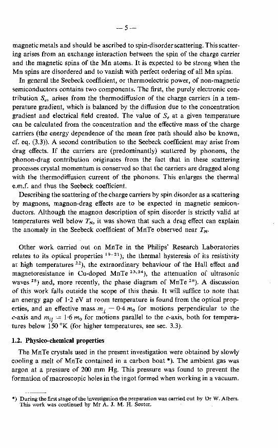
magnetic metals and should be ascribed to spin-disorder scattering. This scattering arises from an exchange interaction between the spin of the charge carrier and the magnetic spins of the Mn atoms. It is expected to be strong when the Mn spins are disordered and to vanish with perfect ordering of all Mn spins.
In general the Seebeck coefficient, or thermoelectric power, of non-magnetic semiconductors contains two components. The first, the purely electronic contribution Se, arises from the thermodiffusion of the charge carriers in a temperature gradient, which is balanced by the ditrusion due to the concentration gradient and electrical field created. The value of Se at a given temperature can be calculated from the concentration and the effective mass of the charge carriers (the energy dependenee of the mean free path should also be known, cf. eq. (3.3)). A second contribution to the Seebeck coefficient may arise from drag effects. If the carriers are (predominantly) scattered by phonons, the phonon-drag contribution originates from the fact that in these scattering processes crystal momenturn is conserved so that the carriers are dragged along with the thermodiffusion current of the phonons. This enlarges the thermal e.m.f. and thus the Seebeck coefficient.
Descrihing the scattering ofthe charge carriers by spin disorder as a scattering by magnons, magnon-drag effects are to be expected in magnetic semiconductors. Although the magnon description of spin disorder is strictly valid at temperatures well below TN, it was shown that such a drag effect can explain the anomaly in the Seebeck coefficient of MnTe observed near TN·
Other work carried out on MnTe in the Philips' Research Laboratories relates to its optical properties 19- 21 ); the thermal hysteresis of its resistivity at high temperatures 22), the extraordinary behaviour of the Hall effect and magnetoresistance in Cu-doped MnTe 23•24), the attenuation of ultrasonic waves 25) and, more recently, the phase diagram of MnTe 26). A discussion of this work falls outside the scope of this thesis. It will suffice to note that an energy gap of 1·2 eV at room temperature is found from the optical properties, and an effective mass m 1 = 0·4 m0 for motions perpendicular to the c-axis and m11 1·6 m0 for motions parallel to the c-axis, both for temperatures below 150 °K (for higher temperatures, see sec. 3.3).
1.2. Physico-chemical properties
The MnTe crystals used in the present investigation were obtained by slowly cooling a melt of MnTe contained in a carbon boat *). The ambient gas was argon at a pressure of 200 mm Hg. This pressure was found to prevent the formation ofmacroscopic holes in the ingot formed when workingin a vacuum.
*) During the first stage of the investigation the preparation was carried out by Dr W. Albers. This workwas continued by Mr A. J. M; H. Seuter.

-6
The temperature of the melt before cooling was begun was 1470 °K. Under the above conditions of preparation, solidification occurs at about
1440 oK and the crystals formed have the NaCI structure initially. Upon further cooling a fust-order transition point is reached at 1312 oK where the crystals transform into the NiAs structure. This modification appears to be stabie down to the lowest temperature used in the present investigation (cf. ref. 27). The first-order transition is the probable cause of the fact that the crystals finally obtained are far from perfect and show many fractures and dislocations.
Recently Van den Boomgaard 26) has investigated the phase diagram of the Mn-Te system near the equiatomic composition. He finds that it should be possible to obtain crystals of MnTe which grow directly in the NiAs structure. The conditions which must be satisfied are, however, rather difficult to fulfil and no crystals have been grown in this manner. At ordinary temperatures the crystals made by the metbod followed by Seuter always contain precipitates of MnTe2 •
The homogeneity range of MnTe is found to be very smallandtolie probably entirely on the Te-rich si de of the stoichiometrie composition. It may be assumed that the p-type conductivity found in undoped material is connected with the deviation from stoichiometry. Changes in the equilibrium between the singlephase MnTe and the MnTe2 precipitates or the vapour phase also cause a change in hole concentration. This mechanism was proposed by Seuter 22) as being the probable origin of the effects of thermal hysteresis in the resistivity which are observed in MnTe at temperatures above 400 °K 4 •27).
Doping of the crystals may be achieved by adding the dopants to the starting materiaL Incorporation of Na increases the p-type conductivity 6), indicating that Na acts as an acceptor. High-resistivity material may be obtained by adding
c
•Mn o Te
Fig. 1.1. The crystal structure of MnTe; the right-hand figure is the unit cell.

-7
Cr (cf. ref. 7), but the MnTe thus prepared remains p-type. ApparentlyCracts as a donor but its solubility does not exceed the concentration of native defects acting as acceptors. Another possibility is that the concentration of Cr atoms exceeds the concentration of native defects but that their donor level is closer to the valenee band than to the conduction band.
The NiAs structure is shown in fig. l.I. It may be thought of as an h.c.p. lattice of the anions in whose octahedral sites the cations are located. The latter form a simpte hexagonallattice. For MnTe the c/a ratio is 1·62 28
), which is close to the ideal value of (8/3)112 1·63, corresponding to a perfect octahedral coordination of the cations. The crystallographic unit cell contains two anions and two cations, all betonging to different c-planes (planes perpendicular to the c-axis).
1.3. Magnetic properties
The magnetic susceptibility of MnTe has a maximurn near 328 oK 4 ), but the magnetic-ordering temperature, or Néel temperature TN, is somewhat lower, 307 °K. This value has been established in several ways, e.g. from an abrupt decreasein the specific heat 29) and, very accurately, from a sharp peak in the attenuation of ultrasonic waves 25), botheffects presumably taking place at TN. The change of slope at T N of the resistivity vs temperature curve has been used to investigate the pressure dependenee of TN 30).
Above 600 oK the susceptibility follows the Curie-Weiss law x C/(T + 8) with an asymptotic Curie temperature () of 600 to 700 oK 4 •31). The Curie constant C corresponds to a magnetic moment of five Bohr magnetons per Mn atom, in agreement with an expected 6S configuration for five unpaired 3d electrons on each Mn atom 27).
The magnetic structure in the antiferromagnetic phase below TN has been determined from the anisotropy of the magnetic susceptibility 31) and from neutron diffraction 27
•32
). It is found that the average spin directionsof the Mn atoms in each c-plane are parallel to each other and antiparallel to those of the Mn atoms in the next c-plane. The magnetic unit cell is thus identical with the crystallographic unit cell.
There are relatively strong anisotropy forces causing the spin direction to be oriented perpendicularly to the c-axis, but the forces coupling the orientation to any particular direction within the c-plane are much weaker 31
).
This direction has not been determined experimentally. It can be shown, however, that if the preferred direction of sublattice magnetization is notalong the Mn-Mn direction, weak ferromagnetism is possible 23 •24). Since weak ferromagnetism is not usually observed in MnTe, it seems likely that the direction of preferred sublattice magnetization is normally along the Mn-Mn direction.

-8-
2. EXPERIMENTAL METHODS
This chapter contains a description of the experimental set-up used for measuring the resistivity, Hall coefficient and Seebeck coefficient. Calculations and applications of a new and sensitive metbod for determining anisotropies of the resistivity are given.
2.1. Experimental arrangements
2.1.1. Resistivity and Hall effect
Most measurements on MnTe reported here were performed using the metbod of Van der Pauw 33 •34) (see also sec. 2.2). The dimensions of the samples were ahout 5 x 5 x 0·5 mm 3 and silver paste was used for making electrical contacts.
The various components of the electdeal equipment used for the measurements are shown in the hlock diagram of fig. 2.1. The measuring current is
Fig. 2.1. Block diagram of apparatus used for resistivity and Hall-effect measurements~
drawn from ten 1· 5-V air-depolarized cells. Currents ranging from 0· 5 to 100 mA are ohtained hy stepwise variation of the series resistance of the circuit. The voltmeter is a Keithley model 150A d.c. Microvolt-Ammeter. The zero suppression up to 100 times full scale of this instrument can be used conveniently for compensating the voltage drop across the Hall probes. lts output is connected to a Philips PR 4069 M/06 recorder. Por the Hall measurements thè u se of a recorder instead of directly reading a voltmeter has several advantages. It allows less stringent demands on temperature stahility, the performance of the measurements is facilitated and in some cases the recorder trace shows details which otherwise would easily he overlooked.
The sample cantactscan he checked by displaying the current through two cantacts as a function of the voltage across these cantacts on an oscilloscope.

-9-
A rectifying contact can usually be made ohmic by discharging a condensor through it.
Five multiple switches serve for making the desired connections between the units described and the leads to the sample. The leads consist of thin copper wires (100 !Lm) and are twisted around each other in order to diminish piek-up from stray fields. The loop in the voltage circuit is fixed to one of the pole caps of the magnet and is employed for compensating the induction voltage which occurs during changing and switching of the magnetic field. With the ten-turn 100-Q potentiometer (R) the compensation by the loop can be adjusted accurately.
Many measurements were carried out at temperatures between 77 and 350 oK in a magnet giving 5 kG. For measurement at higher field strengtbs a special magnet was designed in cooperation with Dr D. H. Kroon (cf. ref. 35). It attains a maximum field of nearly 23 kG in an air gap of 22 mm (at 90 A and 90 V); its weight is only 500 kg. The magnet current is obtained by rectification of a 380-V three-phase rnains supply and is continuously variable.
The small air gap of this magnet necessitated a special apparatus for performing measurements at various temperatures. It is shown in fig. 2.2. The sample (I) is fixed to the cadmium-plated copper sample holder (fig. 2.2a) by means of four phosphor-bronze springs (2) pressing against the dectrical con-
7 8 ~ 17
7 10 11 12
6 13
4 14 5 15
J..------1
1cm
a) b) c) e)
Fig. 2.2. Apparatus for Hall-effect measurements between 200 and 350 °K in magnet (21) with 22-mm air gap. For explanation, see text.

-10-
tactsof the sample. Thin mica discs (dashed lines 4) fix the springs by turning on the screws (3) and serveforelectricalinsulation. Thelead wires (5) are soldered to the springs. The sample holder is connected to a roetal disc (8) by means of a novotex rod (7), fig. 2.2b. The measuring leads (5) and a thermocouple (6) pass through the disc (8) via thin molybdenum tubes sealed in glass (9).
After the sample has been mounted the sample holder is lowered into an open double-walled glass tube (18), fig. 2.2d. This tube is silvered internally and the interspace is evacuated (the seal is not shown). It is provided with a roetalflange (17) to which the disc (8) is fastened. In the tube the sample holder is surrounded by the heating element, fig. 2.2c. lts lower part (13) consists of a copper tube covered with an insulating layer of Al20 3 on which a heating wire (14) is wound. This wireis connected to leads (16) by means of screws in an asbestos block (15) which also serves for centring the heating element in the glass tube. The upper part (11) of the heating element is made of stainless steel and contains four holes (12). The asbestos piece (10) serves for suspending the heating element in the glass tube.
For cooling the sample a rubber tube (20) reaching into a Dewar vessel (22), fig. 2.2e, has been fitted to the lower part of the glass tube. The Dewar vessel can be :filled with liquid nitrogen which will evaporale in proportion to the heat developed in a resistor (23) located within the rubber tube. The nitrogen vapour passes along the lower part of the heating element which now mainly serves for protecting the sample from rapid temperature fluctuations. Due to the asbestos part (10) the vapour is forced to flow through the holes (12) and through the upper part of the heating element. This reduces the heat inflow from above along the measuring leads and thermocouple. The vapour leaves the apparatus through the outlet (19).
To avoid cracking, the temperature ditTerenee between the inner and the outer glass tube may not be too large, so that only a limited temperature range around room temperature can be covered. Sufiicient stability of the sample temperature is obtained by a constant heat input in the heating element (13) for measurements above room temperature, or in the resistor (23) in the nitrogen bath for measurements at lower temperature. In the latter case it is necessary, however, to maintain a constant nitrogen level in the Dewar vessel.
2.1.2. Seebeck effect
In conducting matenals a temperature ditTerenee LlT creates an electromotive force Ll V. For small temperature ditierences the ratio Ll VjLlT is called the Seebeck coefficient or thermoelectric power, and will be denoted by S.
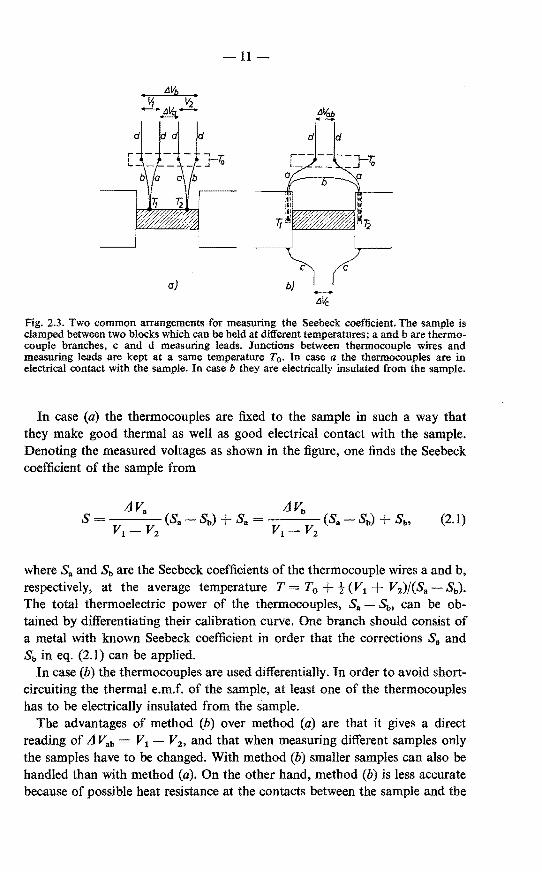
Thermocouples are conveniently used for measuring the temperature difference. Two elementary ways of obtaining S using thermocouples are shown in fig. 2.3. In both cases the sample is clamped between two (metal) blocks which are maintained at different temperatures.
11-
a) +----»
6~
Fig. 2.3. Two common arrangements for measuring the Seebeck coefficient. The sample is clamped between two blocks which can be held at different temperatures; a and b are thermocouple branches, c and d measuring leads. Junctions between thermocouple wires and measuring leads are kept at a same temperature T0 • In case a the thermocouples are in electrical contact with the sample. In case b they are electrically insulated from the sample.
In case (a) the thermocouples are fixed to the sample in such a way that they make good thermal as well as good electrical contact with the sample. Denoting the measured voltages as shown in the figure, one finds the Seebeck coefficient of the sample from
s (2.1)
where Sa and Sb are the Seebeck coefficients of the thermocouple wires a and b, respectively, at the average temperature T = T0 + t (V1 V2)/(Sa- Sb). The total thermoelectric power of the thermocouples, Sa - Sb, can be obtained by differentiating their calibration curve. One branch should consist of a metal with known Seebeck coefficient in order that the corrections Sa and Sb in eq. (2.1) can be applied.
In case (b) tbe tbermocouples are used differentially. In order to avoid shortcircuiting tbe tbermal e.m.f. of the sample, at least one of the tbermocouples has to be electrically insulated from the sample.
The advantages of metbod (b) over metbod (a) are that it gives a direct reading of L1 Vab V1 - V2 , and that when measuring different samples only tbe samples have to be changed. With metbod (b) smaller samplescan also be handled tban witb metbod (a). On tbe other hand, metbod (b) is less accurate because of possible heat resistance at tbe contacts between the sample and the

-12-
heating blocks *). In case (a) this heat resistance does not affect the measurements.
An accurate measurement of the Seebeck coefficient of a low-ohmic sample of MnTe (0·02 0 cm at room temperature) has been obtained by employing a method proposed by Dauphinee and Mooser 36 •37). This method combines the advantages of methods (a) and (b) by giving a direct reading of L1 v.b with the absence of troublesome heat resistance. The principle of the measurement is shown in the upper part of fig. 2.4. The sample and
Fig. 2.4. Dauphinee-Mooser circuit used for accurate measurements ofthe Seebeck coefficient. Switches S1 and S2 vibrate simultaneously at a rate of about 40 cycles per second, charging condenser C2 to voltage Ll Vab· Resistances R 1 = 20 kfl, R 2 = 7 kQ and R 3 = 3 kQ permit fraction {1 = 1, 1/3 and 1/10 of the thermal e.m.f. Ll V tó be measured on the same scale of the voltmeter as Ll Vab·
thermocouples are mounted as for method (a). The motor-driven "breakbefore-make" switches sl and s2 vibrate simultaneously at a rate of about 40 cycles per second. In this way the condensor C1 is charged to the voltage delivered by the thermocouple to the left, cl + c2 to the voltage delivered by the thermocouple to the right. The difference between the two voltages L1 v.b will then be found across C2 • This voltage is measured by a Keithley 150A connected to a Philips recorder, as for the measurement of the Hall effect.
*) Such heat resistance shows up as a hysteresis effect in the Ll V vs Ll T curve. It is noted that in all cases it is necessary to measure Ll V as a function of LlT in order to eliminate smal! differences in the thermoelectric power of the thermocouples as well as spurious e.m.f.s in the measuring circuit. These effects cause the Ll V vs Ll T curve not to pass through the origin.

-13-
The double reversal switch S3 permits of the measurement of the thermal e.m.f. L1 V of the sample with respect to the copper as well as to the constantan wires of the thermocouples. With the resistances R1o R2 and R 3 a known fraction fJ of L1 V can be supplied to the voltmeter so that fJ L1 V and L1 Vab
may be read with the same range setting. Being much larger than all other resistances in the circuit they introduce negligible errors in the results. The connections between the thermocouple wires and their lead wires were immersed in an ice bath in order to proteet them from temperature variations. This was also convenient for using the thermocouples for determining the temperature of the sample.
To perform the measurements we clamped the sample between two copper blocks (fig. 2.5). The thermocouple junctions were immersed in a small amount of
CID
CID
Screws
I cm >---------<
Sample
Thermocouple Nuts
Springs Rods Heatsink
Fig. 2.5. Device used for creating a temperature gradient in a sample by means of a Peltier element.
a liquid metal alloy which had been brought into two grooves made in the sample. One of the copper blocks was clamped on top of a Bi2 Te 3 Peltier element and was cooled or heated depending on the direction of the current passed through this element. The whole device was placed in a copper tube whose temperature could be controlled between 77 and 330 °K.
The voltages L1 Vab and fJ L1 V could be recorded alternately during 3 and 7 seconds, respectively, the duty cycle of 10 seconds being obtained by means of a motor-driven microswitch. A drawing of a typical recorder trace during some successive reversals ofthe current through the Peltier element (and a continuous

-14-
Cooling •I
Heating •I
Cooling
(3 t.V
/T' / ((3.tN}, \
, ....... --· \ I t \ .-----!'•,
1 ••• r~VatJ, .. L __ ,__, __ __,
5 min
•I Heating
f·, I ·.,
•,
.-----
----Time
Fig. 2.6. Recorder trace obtained with apparatus shown in figs 2.4 and 2.5; L1 Vab and f3 L1 v. are recorded alternately during 3 and 7 seconds, respectively. Cooling and heating refer to the top of the Peltier element (cf. fig. 2.5). During the time that no trace is shown, measurements of temperature and resistivity were taken. Horizontal arrows indicate crossings of L1 Vab and L1 v. traces and show absence of thermal hysteresis. Vertical arrows indicate two ways of obtaining the relevant data for calculating the Seebeck coefficient of the sample.
change of the overall temperature of the measuring device) is shown in fig. 2.6. The L1 v.b and fJ L1 V traces interseet at the same distance below the zero axis for both directions of the current through the Peltier element, which shows the absence of a hysteresis effect due to a possible poor thermal contact between the thermocouples and the sample. That the two traces do not interseet on the zero axis is due to spurious e.m.f.s in the circuit andfor inequality of the thermocouples (cf. footnote above).
During the time for which fig. 2.6 shows no traces the voltages L1 v.b, fJ L1 V, L1 V1 and L1 V2 were read directly on the voltmeter for both positions of the switch S 3 (for determining the resistivity the change of fJ L1 V was also observed when a given current was passed through the sample via the copper blocks; actually these measurements were usually made after the temperature difference across the sample had been niade constant by adjusting the current through the Peltier element). From these readings the Seebeck coefficient was obtained from the voltages indicated in fig. 2.6 by the vertical arrows ({J L1 V) 1
and (Ll v.b)1 • Another possibility is indicated by the vertical arrows ({J L1 Vh and (Ll v.bh·
From the readings for the two positions of the switch S3 it was possible to calculate the Seebeck coefficient of the sample both with respect to copper, S- Scu, and with respect to constantan, S- Sconst ( cf. eq. (2.1 )). For all measurements the relation
(S- Scu) = (S- Sconst) + (Sconst- Scu) (2.2)
was satisfied within two per cent. An impression of the reproducibility of the metbod is given by fig. 2.7, which shows the results ofmeasurements at various temperatures on the MnTe sample mentioned. Below 200 oK the Bi2 Te 3

15-
T@mperature Overall temperature of top of
Peltier elem. up down const. t.Jp
down .. •
• "
" "
250 300 ----- T(°K)
Fig. 2.7. Result of measurements of the Seebeck coefficientof an MnTe sample. Forsome points the change of average sample temperature during the measurement is indicated.
element was less effective in producing temperature differences across the sample and the measurements were somewhat less accurate than at higher temperatures.
It is remarked that with the device used at a constant ambient temperature one obtains a difference in average sample temperature for the two current directions through the Peltier element which is often much larger than AT. When, however, measurements are carried out while continually changing the ambient temperature, every second measurement can be made in such a way that it refers to a nearly constant average sample temperature. This is shown, e.g., by the four successive measurements between 254 and 263 °K. The Secbeek coefficient of the sample is given below in fig. 3.2a.
2.2. A metbod for determining the anisotropy of the resistivity
2.2.1. The Van der Pauw method
In an earlier paper 38) a method was described by which the components of the resistivity of an anisotropic conductor can be obtained by means of a customary four-probe resistivity measurement (equally spaeed probes in a collinear or square arrangement). This method requires samples with dimensions large compared to the spacing of the probes, otherwise complicated corrections have to be applied. In the present section another method will be discussed which does not impose such a condition and which, furthermore, has been found to be more sensitive.

-16
The metbod may be regarded as a special case of the Van der Pauw metbod 33 •34) for measuring resistivities. For applying the latter metbod a fiat sample (of arbitrary shape but with no holes in it) is provided with four contacts P, Q, Rand S at its circumference and two "resistances" R 1 and R 2 are measured. R 1 is defined as RPQ.RS• i.e. the voltage across the contacts R and S per unit current passed through the contacts P and Q. Similarly R 2 = RoR.sP·
If the sample is isotropie it can be shown that R 1 and R 2 do notchange by conformat mapping of the sample onto some other shape. Taking for this other shape a half-plane, as e.g. in fig. 2.8d, it follows from elementary theory that
R =R =-ln --·--e (R'P' S'Q')
t PQ,RS 7€ d R'Q' S'P' , (2.3a)
R- - ln · e (S'Q' P'R') 2 - RoR,SP - 7€ d S'R' P'Q' , (2.3b)
where e and d are the resistivity and the thickness of the sample, respectively; R'P' denotes the distance between the image points of Rand P, etc .. Van der Pauw proceeds by noting that
R'Q' S'P' S'R' P'Q' ·-+ . =1
R'P' S'Q' S'Q' P'R' so that
exp (-n R 1 d/eJ exp (-:n: R2 d/e) = 1,
which may also be written as
:n:d -- (Rt + R2)f(R1/R2), 2ln 2
(2.4)
(2.5)
(2.6)
f(RtfR2) being a complicated function of the ratio R 1/R2 which is given by Van der Pauw in graphical form *). The surprising element in tbe metbod is tbat the sbape of the sample and the position of the contacts need not be known. These geometrical factors enter into the calculation of e only in so far as tbey determine tbe ratio R 1 /R2.
The metbod for measuring anisotropic resistivities proposed here is based on the fact that
*) Some parts of the curve as reproduced in Van der Pauw's paper 33) deviate from the correct curve by a few per cent. A useful parametrie relation for calculating the curve is
log-! R 1 log(t-x) f(R 1 /R1) = log(! +x) + log (t- x} ; Rz = log H+ x}'
with --t <x < t (cf. eq. (2.20)}.

-17
(1) for an isotropie sample of simple geometry the ratio R 1/R2 of the Van der Pauw metbod ean be ealculated explieitly, and
(2) an anisotropie sample with resistivities e1 (i = 1, 2, 3) along the three prineipal (mutually orthogonal) axes x1 is eleetrieally equivalent to an isotropie sample whose dimensions x/ are related to the dimensions x 1 of the anisotropic sample by 34·39)
(2.7)
and whose resistivity is
e Ü!I ez e3)113
• (2.8)
Caleulations will be given below for reetangolar and eireular samples.
2.2.2. Reetangu/ar samples
Consicter a flat, anisotropie, reetangolar sample of length /1 , width /2 and thiekness / 3 with its edges parallel to the direetions of the principal resistivities et. ez and e3 , and provided in a symmetrieal way with two pairs of contaets at distances a 11 apart (a~ 1) as shown in fig. 2.8a. Aecording to eqs (2.7) and (2.8) the sample is eleetrieally equivalent to an isotropie sample with resistivity e = (el ez 123)113 and dimensions lt' = (et/e) 112 ft (fig; 2.8b).
It is well known (see e.g. refs 40 and 41) that the sine-amplitude funetion
I
[
I
12 ~~
'--!-: _L _______ PI-!,:,.--i ! J. R a) S
c)
z-plane
w = sn (z,k)
l' ,. 1
af all
12[1 j •1 I ,_p
R' b)
A' B' I C' . I I • •I
i -7/k -1 i j1 Q'' R" S"
d)
w-plane
(2.9)
lp• .1
l l s·
D' I
1/k i P"
Fig. 2.8. Anisotropic rectangular sample with edges parallel to principal directions of e; (a): the sample, (b): transformed into an electrically equivalent isotropie sample, (c): isotropie sample in z·plane, (d): sample mapped onto Im w ;;;. 0.

-18-
conformally maps the interior of a rectangle with sides 2 K(k) and K'(k) situated in the z-plane as shown in fig. 2.8c, onto the upper half of the w-plane (fig. 2.8d). Here K(k) and K'(k) are the complete elliptic integrals of the first kind and its associate, respectively. They are functions of the modulus k. The shape of the rectangle is determined by the ratio K(k)/K'(k), i.e. by the value of k. Compilations of mathematica! tables usually do not give K(k)/K'(k) as a function of k, but rather the gnome q(k) = exp {-n K(k)/K'(k)} as a function of k or of arcsin k.
A trivial transformation preserving the ratio lt'/12 ' maps the sample of fig. 2.8b conformally onto the rectangle of fig. 2.8c so that the appropriate value of k for the sample considered can he obtained from the tables of q(k) with
q(k) = exp ( -n :) (2.10)
Here, as in the formulae given below, we omit in the notation the explicit dependenee of the various elliptic functions of k, it being understood that in all expressions k has the same value, viz. that determined by eq. (2.10).
With the transformation (2.9) and the properties of the sine-amplitude function the position of the images of the contacts in the w-plane become (fig. 2.8d)
w(P") = sn(aK+ iK') {ksn(aK)}- 1,
w(Q") = sn (-a K +iK')= -{k sn (a K)}- 1 ,
w(R") = sn (-a K) -sn (a K),
w(S") = sn (a K).
(2.11a)
(2.llb)
(2.11c)
(2.lld)
Substituting the distances P"Q" = w(Q")- w(P"), etc. in eqs (2.3a) and (2.3b) one finds that
(1!1 ez)112 I+ ksn2 (aK) (2.12a) R1 2ln--·· ,
n /3 I k sn2 (a K)
Rz (et e2)112
2ln 1 + ksn2 (aK)
(2.12b) -·--n 13 2 k 112 sn (a K)
From these equations the ratio R 1/R2 bas been calculated as a function of (/1
2 e1)f(ll e2) for a I, 5/6, 2/3, 1/2, 1/3 and 1/6. The result is shown in fig. 2.9. These curves permit etfe2 to he obtained from measured values of R1/R2 , 11/!2 and a. The value of e1rh follows from replacing e by (e1 e2 )
112
in eq. (2.6). It should he noted that the application of this metbod requires the knowledge
of the directions of the principal axes of the resistivity tensor. If the plane of

-19-
Fig. 2.9. R 1 /R 2 for reetangolar samples as a function of 112 (! 1 /12
2 (!2 for different values of the fraction a (see fig. 2.8a).
the sample is not perpendicular to the direction of (} 3 the results obtained refer to the principal "sheet resistances" (! 1 and (! 2 in the plane of the sample.
2.2.3. Circular samples
A flat anisotropic circular sample (fig. 2.10a) of radiusrand thickness d with its plane perpendicular to the direction of the principal resistivity e3 is electrically equivalent to an isotropie elliptic sample with semi-axes a r ((} 1/(})112
and b r ((!2 /(!)112, and with a thickness d' = d (e 3 /(!)112, (} being again
equal to (e 2 e1 (! 3 ) 113• The circumference of this ellipse may be represented in the z-plane (fig. 2.10b) by
Q
a)
z-plone
R'
Semiaxes a=r\jfi>b=r'{{j
b)
w-plcme
Radius 1
c)
Fig. 2.10. Anisotropic circular sample; (a): the sample, (b): transformed into an elliptical, electrically equivalent isotropie sample, (c): the sample conformally mapped onto the unit circle.

-20-
z = a cos q; + i b sin q; = (a 2- b2)112 cos (q;- ie), (2.13)
(supposing !?1 > !?2) with
exp (-c) = (a- b)(a2- b2)-1/2 = (e11/2- e//2)(e1 - !?2)-112. (2.14)
This ellipse will first be transformed conformally into a unit circle (fig. 2.10c), which is achieved by
w = k 112 sn - arcsin k (2K z ) n (a2 _ b2)1;2 '
(2.15)
if the modulus k satisfies
(
n K') (e11/2- e/12)4 q(k) = exp - - = exp (-4 c) = -----
K Ce1- !?2)2 (2.16)
Like eq. (2.10) the later again determines the appropriate value of k fora given
ratio ede2· By substituting (2.13) and 4 c = n K'/K (cf. (2.16)) into (2.15) (and using
the properties of the sine amplitude and related functions), the image of a point r exp (iq;) on the circumference of the original circle on the unit circle w = exp (i'rp) is found to be
w = k 11
2 sn (2 K q;/n + K- i K'/2, k) =
(1 + k) sn (u+ K)-icn(u + K)dn(u + K)
1 + k sn2 (u + K)
en u dn u+ i (1- k) sn u
1-k sn2 u
(2.17)
The functions en (u, k) and dn (u, k) are re1ated to sn (u, k) by cn2 u =
1- sn2 u and dn2 u= 1- P sn2 u. Inthelast partsof (2.17) the modulus k has been omitted in the notation and u has been written short for 2 K q;/n.
The interior of the unit circle I w I = 1 is mapped conformally onto the upper half-p1ane Im t ;;;::: 0 by, e.g.,
This gives
w-i t=---
-iw + 1
cos tp !=---
sin tp + 1
(2.18)
(2.18a)

21-
fora point on the circumference, w exp (itp). The final formula for the image of any point of the original circle r exp (iep) on the axis Im t = 0 is obtained by substituting (2.17) into (2.18). Using eqs (2.3a) and (2.3b), R 1 and R2 can then be calculated for any arrangement of the contacts and any value of (! 1
and (!2 (as in the case of the rectangular samples, (!3 does not enter into the final results).
It will, of course, be advantageous to choose a simple geometrical arrangement. lf the contacts are placed in such a way tbat they He on two perpendicular diameters, a rather long but elementary calculation gives the simple re sult
Ü!l (!2)112 ln 2 R1 (2.19a)
:red 1- k sn (2 u)'
(el e2)1t2 ln 2 R2 (2.19b)
:red 1 k sn (2 u)'
where u 2 K(k) cpj:n, cp being the angle between one of the principal axes of the resistivity and a line connecting two opposite contacts.
Figure 2.11, on a normalized scale, shows the dependenee of R 1/R2 on cp for various values of ede2. Using this figure it is possible to determine the directions of the principal axes by making measurements rotating the contacts (at angles :n/2 apart) around the circumference of the sample. If the results of
ltl{R,IR<)
~n(R1 1R2 J]cp=,:So
t 0·8
0·6
0·2
I
A V
A W'
ff '{/
I
10
~ "",..
A
h fj /; ~
@ '-4 -10
lij V -20 I
~
20
Fig. 2.11. Dependenee of In (R 1 /R 2 ) on angle of rotation cp for anisotropic circular samples with fhifh = 1·1, 4, 10 and 20, respectively. ·

-22-
such measurements deviate from the expected curve, the sample must be inhomogeneous.
The maximum value of R 1/R2 occurs if g; = n/4, for which sn (2 u)= 1.
In that case
( ) 1/2 2 (R) = e1 e2 In
lmax nd 1 k' (2.20a)
(el e2)112 2
(R2)mtn = In , nd 1 +k
(2.20b)
In H(l-k)} (R/R) - ·
1 2 max - In H (1 k)} ' (2.20c)
(R1/R2)max is shown as a function of e1/e 2 in fig. 2.12.
2.2.4. Sensitivity of the method
In fig. 2.12 the dependenee of RtfR2 on etfe2 for the proposed methods (curves 1 and 2) and the earlier ones 38) (curves 3 and 4) are compared. The figure demonstrates the extreme sensitivity of the new methods. lt should be remarked, however, that the accuracy of the determination of ede2 also depends on the accuracy achieved in obtaining the proper geometry.
1·5 2 4 s 6 7 8 910
---Pr1P2
Fig. 2.12. Comparison of different methods of determining fhlfh from R 1 /R 2 ; (1): square sample with contacts at the corners, (2): circular sample with n = t:p/4, (3) and (4): four probes in a square on a large thick and a large thin sample 38).
23-
The influence of deviations from the proper geometry and of the finite dimensions of the contacts have not been investigated. The fact that in the case of rectangular samples the R 1/R2 vs (h/fb curves for a = 1 and a 5/6 lie close together (fig. 2.9) suggests that forthese geometries the factors mentioned should not influence the results very drastically. The maximum at qy 45° in the curves of fig. 2.11 also ensures that for circular samples the 45° positions of the contacts with respect to the resistivity axes are not extremely critical.
2.2.5. Applications
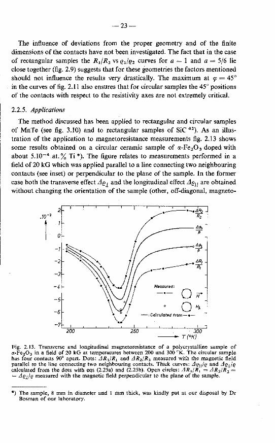
The metbod discussed has been applied to rectangular and circular samples of MnTe (see fig. 3.10) and to rectangular samples of SiC 42). As an mustration of the application to magnetoresistance measurements fig. 2.13 shows some results obtained on a circular ceramic sample of a:-Fe20 3 doped with about 5.10- 4 at.% Ti*). The tigure relates to measurements performed in a field of 20 kG which was applied parallel to a line connecting two neighbouring contacts (see inset) or perpendicular to the plane of the sample. In the former case both the transverse effect Lle1 and the longitudinal effect Lle11 are obtained without changing the orientation of the sample (other, off-diagonal, magneto-
2 .10-3
l 0
-1
-2
-3
-4- ~
-5
-6
-7 200 250
____ tJp/1
p
OH 0 H1
-: Calculated from -•-
300 ---- T(°K)
Fig. 2.13. Transverse and longitudinal magnetoresistanee of a polyerystalline sample of a-Fe20 3 in a field of 20 kG at temperatures between 200 and 300 °K. The cireular sample has four eontacts 90° apart. Dots: LJR 1/R1 and LJR2 /R 2 measured with the magnetic field parallel to the line connecting two neighbouring contacts. Thick curves: LJ g11 I(! and LJ C!il (! calculated from the dots with eqs (2.25a) and (2.25b). Open circles: LJR1 /R 1 = LJR 2 /R 2 = LJelht measured with the magnetic field perpendicular to the plane of the sample.
*) The sample, 8 mm in diameter and 1 mm thick, was kindly put at our disposal by Dr Bosman of our laboratory.

-24
resistance effects should he absent in perfectly disordered polycrystalline material). Denoting the resistivity at zero field by eo one may put
(!1 = eo + Llel (!o (1 + 61),
(!2 = eo + Lle/1 = eo (I + 61/).
(2.2la)
(2.21b)
Since the resistance changes are small eq. (2.16) may be expanded in powers of k and of the ds. Retaining first terros only one has
(2.22)
that is (2.23)
The direction of the magnetic field considered corresponds to rp n/4, i.e. sn (2 u)= 1 and (2.19) reduces to
( )1/2
R1 R::J e1 e2 (ln 2 + k), (2.24a)
nd
( )112 R2 R::J e1
(!2
(ln 2- k). (2.24b) nd
Using (e1 e2)112
R::J eo (1 + t d 1 + t d11) and combining eqs (2.21), (2.23) and (2.24) one finds that the relative changes d 1 and d11 of the resistivity follow from the observed relative changes r 1 = LIR1/R 1 and r2 = LIR2 /R 2 according to
61 r 1 -0·327(r1 r2),
d11 r 2 + 0·327 (r 1 - r 2 ),
where 0·327 - t ~ (ln 2)/4.
(2.25a)
(2.25b)
As fig. 2.13 shows, the values obtained for 61 Lle1!e with these equations from the measurements with the magnetic field in the plane of the sample are in good agreement with the values directly observed with the magnetic field perpendicular to the plane of the sample.
(The physical significanee of these measurements will not he discussed; it is only noted that the temperature of the maximum of Lle/e I roughly coincides with the transition point from antiferromagnetism to weak ferromagnetism.)
Haas et al. 43) have used the method described above to establish the fact that the exceedingly large magnetoresistance of n-type CdCr2Se4 around 120 oK is essentially isotropic.
-25
3. EXPERIMENTAL RESULTS AND DISCUSSION
In the fi.rst section of this chapter the main experimental data on the electrical properties of p-type MnTe between 77 and 350 °K are presented and their most prominent features are briefly reviewed. The sections which follow discuss in detail the Hall coefficient, the resistivity and Seebeck coefficient, and the mobility. Finally, measurements on the anisotropy of the resistivity are presented and some remarks are made on magnetoresistance effects.
3.1. Survey of main experimental results
3.1.1. Measurements of Hall coefficient, resistivity and Seebeck coefficient
Figures 3.la and b show a number of resistivity e(T) and Hall-coefficient RH(T) curves obtained at temperatures between 77 and about 350 °K. The curves are representative of more numerous results of measurements on other samples performed with the conventional Van der Pauw method. The lower curves (1 to 3) refer to Na-doped MnTe, the higher ones (11 to 13) to Cr-doped MnTe. The other samples (4 to 10) were not intentionally doped. Symbols 1 and // mark curves re lating to samples whose plane was oriented perpendicular or parallel to the crystallographic c-axis. The difficulty in obtaining good electrical contacts to high-ohmie samples prohibited the determination of the Hall coefficient of the Cr-doped samples (11 to 13). Most Hall-effect measurements were carried out in a field of 5 kG applied perpendicularly to the plane of the samples. Only for samples I to 3 was the Hall effect measured in fields up to 23 kG at temperatures above 200 oK (see sec. 3.2).
Figure 3.2a, shown below, gives the Seebeck coefficient S(T) of one of our Na-doped samples as well as of two similarly doped samples reported in the literature. The resistivity of these samples is given in fig. 3.2b. Other S(T) and e(T) curves obtained by Milier 6
) are reproduced in fig. 3.3. The choice of scales for S and e is motivated by eq. (3.8) given below. The measurements taken from literature were made on sintered samples and the compositions quoted probably refer to the startingïnaterial. Our crystalline sample contained 0·3 at.% Na (according to spectrochemical analysis) and was measured with the temperature gradient and the electrical current perpendicular to the c-axis.
3.1.2. Theoretica! formulae
In the interpretation of the experimental data reported above, the possibility of mixed conduction by holes as well as electrous may be disregarded for a number of reasons, such as the wide energy gap of about 1·2 eV, the wide range of resistivities and Seebeck coefficients found for different samples, and the approximate temperature independenee of the resistivity and Seebeck coefficient

-26
103 .-~~-r-..-~~r,~-.-r-..-~~~~ p
(.fl cm) 11-13 Cr-doQed
12
4- 10 undoeed
1-3 Na-doeed
Fig. 3.1. (a) Resistivity I! and (b) (next page) Hall coefficient RH of some MnTe samples as determined by the Van der Pauw method. Samples l to 3 contained 0·3 at.% Na, samples 11 to 13 were doped with Cr; the other samples were not intentionally doped but had received different heat treatments. Symbols 1 and 11 label samples having their plane perpendicular and parallel to the c-axis, respectively. All Hall coefficients were positive except for samples 2 and 3 at temperatures above 305 °K.
at temperatures well above TN (cf. fig. 3.3). The positive sign of S (as well as of RH11) indicate p-type conduction, i.e. conduction by holes.
The standard equations (see e.g. refs 44 and 45) for interpreting the Hall coefficient, resistivity and Seebeck coefficient for a semiconductor with hole concentration p, and mobility p, determined by a scattering mechanism leading to a mean free path of a hole with energy E proportional to E' are *)
'") Usually the "scattering parameter" r has a value between 0 (e.g. forscattering by acoustical phonons) and 2 (for ionized-impurity scattering).

-27-
4- 10 undo~ed
101!
oS +7
1-3 Na-do~ed
10-4:---'-----'----'----~-=-'"""--'----.J.......i--=-=-=:-'--'---'___.__,~.J.......i---'--,--'--,-l 0 100 200 300 400
b) ------<._T (oK)
Ru= Yu!P e,
e = 1/p e p,,
Fig. 3.1 b.
{ fr+l('fJ) }
Se= (k/e) (r + 2)---'f} F,(rJ) ,
~ (kje) {r + 2 +In (NvfP)}
~ (kje) ::.__ -- (r + 1)(NvfP)213 ;n;2 ( 4 )2/3 3 3 n 112
for rJ « 0,
for rJ » 0.
(3.1)
(3.2)
(3.3)
(3.3a)
(3.3b)
The Hall coefficient is a third-rank tensor 46). lts symmetry properties allow
it to be reduced to asecond-rank pseudotensor, whose diagonal elements refer to measurements made with the magnetic field applied perpendicular to the
28
plane of the sample. For these diagonal elements the "Hall-coefficient factor" YH usually has a value between 1 and 2, depending on the dominant scattering mechanism.
k is Boltzmann's constant, Nv is the effective density of states of the valenee band,
( m * T )312
= 2·51.1019 -4--- cm- 3,
m0 300
(3.4)
m4* being the density-of-states effective mass of the valenee band, (m4*)3 =
= v (m1m1mk), where v is the number of equivalent valenee-band maxima for each of which the diagonalized effective-mass tensor has components m~> mJ, mk. Fora single valenee-band maximum (v 1) we shall write m4 instead of m4*. Unspecified componentsof the diagonalized effective-mass tensor will be denoted by m, the free-electron mass by m0 • For discussions invo1ving the Seebeck coefficient it may be advantageous to introduce a "Seebeck effective density of states" N 5 and a "Seebeck effective mass" ms according to
Ns = e' Nv ~ (r + 1)312 Nv,
m 5 = e2' 13 m4* ~ (r + 1) m4*,
(3.5a)
(3.5b)
where the ~ sign obtains for all valnes of r of common interest, 0 r 2 *). Fn(11) represents a Fermi integral of order n as a function of the reduced
Fermi energy 11 = EF/kT (see e.g. ref. 45),
1 00
B" de F~~(11) f -----
F(n 1) 1 + exp (e- 11)' 0
(3.6)
~ exp 11 for 11 « 0, (3.6a)
~ {tJ 11 +1 jT(n + 2)}{1 + :2
(n + 1) n 11- 2 + .. .} for 11 » 0. (3.6b)
The top of the valenee band is taken as the zero point of the energy scale and energies are counted positive (negative) when below (above) the top of the valenee band.
For the present discussions EF or 11 may be considered as a measure for the hole concentration,
*) The usefulness of such substitutions is demonstrated e.g. by the metbod of estimating the maximum thermoelectric figure of merit of a semiconductor which we described in ref. 47.

29-
P Nvftd'YJ)
~ Nv exp 'YJ for 'YJ « 0,
4 ~ -- N 17 3
'2 (2 ma* Ep) 3
'2 f3 n 2 n3 for 'YJ » 0. 3 nl/2 v
(3.7)
(3.7a)
(3.7b)
Material for which p » Nv, i.e. 'YJ » 0 is called degenera te. For non-degenerate material, p « Nv and 'YJ « 0. For r = 0 eq. (3.3a) is valid within 10% of Se if S > 160 [.LV/deg or p < 1·4 Nv, and eq. (3.3b) if Se< 130 [.LV/deg or p > 2·1 Nv•
It is noted that eqs (3.3) refer to the "purely electronic" contribution Se to the Seebeck effect arising from the thermodiffusion of charge carriers in a temperature gradient. Other contributions to the Seebeck coeffi.cient may arise from the phonon- or magnon-drag effects, which originate from the dragging of the charge carriers by the thermodiffusion current of phonons or magnons, respectively. These effects are discussed in chapter 5.
Strictly speaking, for a given scattering mechanism the Hall-coefficient factor YH and the mobility p, also depend on the degree of degeneracy (cf. eq. (4.12) given below). This dependenee is neglected in the present chapter.
3.1.3. Preliminary discussion
A remarkable feature of the measurements presented is the change of sign ofthe Hall coefficient which forsome samples (e.g. samples 2 and 3 in fig. 3.1b) occur near 300 °K. Normally such a chánge of sign would indicate the onset of mixed conduction, but as already remarked there are many arguments showing that this interpretation is unlikely. It is noted that this change of sign only occurs in samples cut perpendicular to the c-axis. In samples cut parallel to the c-axis (e.g. like samples 1 and 10) the Hall coeffi.cient does decrease between 240 °K and about 300 °K, but not to the extent that it changes sign. This different temperature dependenee of the Hall coeffi.cient in samples of different orientation shows that RH is highly anisotropic at temperatures near and above TN. Since normal transport theory cannot account for this unusual behaviour some additional measurements have been carried out. These are reported below in sec. 3.2. As discussed in that section it appears that in the temperature region indicated, T > 240 °K, there is an "extraordinary" or "anomalous" contribution to the Hall coefficient which is related to the antiferromagnetic properties of MnTe. This contribution seems to he absent below 240 °K and at these temperatures the hole concentration can be estimated in the normal way from the Hall coefficient. According to fig. 3.1b the hole concentration of the Nadoped and most undoped samples (samples 1 to 8) is thus nearly independent of temperature.
Apart from the anomaly in the Hall coefficient, other interestins features of

s
~i 200
700
-30-
I y· I /
;
' I, 'i I
I•
/,1 I
if I
:J I
" ! w
_ .. , I i k1' I
~.~ 7N I
100 200 300 -T(°K)
a)
1Ö
~~~--~-~~~~--*--+ 5r--+-~~~+--~~--~--~
2c--+-+--+-+-l--rt--H 10-" 1!---_.J..-~--'----=-~--'--:::+::-..w
0 100
b)
Fig. 3.2. (a) The Seebeck coefficient of Na-doped samples; -- our measurements (cf. fig. 2.7),---- measurements by Milier 6) on Na.01 Mn.99Te, .... measurements by Deviatkova et al. 8 ) on Na.01 Mn.99Te. (b) The resistivity of these samples.
s (!JV.l'/deg) 500
400
-s ....... fJ
300
.. ~·· 200
100
1 a L-.....;. ... =···;:::;: .. :·~.·~·:::_: .. =:···~f\-.~ .. -.. = ... -:,:: .. ..,:._--1-.-~---1----1 --1lw'
0 100 200 300 400 500 -T(°K)
Fig. 3.3. Seebeck coefficient and resistivity of four samples of different composition reported by Milier 6). The S and e scales have been chosen such that 198 !J.VtK inS corresponds to one decade in e (cf. discussion to eq. (3.8)). The e scale bas been shifted ve'rtically in such a way that the e curves nearly coincide with the S curves at 320 °K.

31-
the data are the strong increase in resistivity and in the Seebeck coefficient at temperatures near TN, and the change of slope of e(T) and S(T) at TN; this behaviour is shown most clearly by the low~ohmic samples (1 to 3 in fig. 3.1a; c and d in fig. 3.3), but is also apparent in more high~ohmic samples (4 to 8 in fig. 3.1a; a and b in fig. 3.3).
Because of its anomalous behaviour the Hall coefficient cannot be used to determine the hole concentration at temperatures above 240 °K and in the absence of other data the behaviour of the resistivity and Seebeck coefficient can be interpreted in different ways.
In explaining the temperature dependenee of the resistivity and Seebeck coefficient near TN in termsof broad-band conduction, two basically different assumptionscan be made. First (case (1 )), it may be supposed that no appreciable change occurs in the structure and shape of the valenee band near TN. In that case there is no reason why the acceptor-level depth should change, and the hole concentration in undoped and Na-doped samples will be essentially independent of temperature above 240 °K, as it is at temperatures below 240 °K. On this assumption the temperature dependenee of the resistivity is mainly determined by the mobility, and the Seebeck coefficient can only be understood if there is some additional contribution at temperatures above 240 °K. Because of the similarity between the e(T) curves for MnTe and ferromagnetic metals it would seem likely that the mobility originates from spin-disorder scattering. As shown previously 13
•14
) the additional con tribution to the Seebeck coefficient may be ascribed to magnon drag.
It may also be supposed (case (2)) that near TN the shape of the valenee band dependsin some way on the magnitude of the sublattice magnetization (cf. sec. 4.3.2). In this case one bas to reekon with the possibility that both the effective mass and the acceptor-level depth may change markedly near TN. A change in effective mass affects the theoretica! mobility as well as the electronic contribution to the Seebeck coefficient. A varlation in the acceptor-level depth may affect the hole concentration. The observed S(T) and e(T) curves suggest that just below TN with rising temperature the hole concentration decreases (i.e. the acceptor-level depth increases) and/or the effective mass increases.
Elimination of p from eqs (3.2) and (3.3a) gives for non-degenerale samples
S = (kje} {r + 2 + ln (Nv ft e e)} 198log10 (e/eo} l.I. V /deg, (3.8)
with eo - 1 = er+ 2 Nv ft e. According to fig. 3.3 this relation between resistivity and Seebeck coefficient is reasonably well satisfied at temperatures above 240 °K with the same temperature-independent value of eo for all samples. This means that in this temperature region the same temperature dependenee of the hole concentra ti on required to explain the Seebeck effect would also explain the resistivity if Nv ft is independent of the temperature. This condition is satisfied for acoustical-phonon

32
scattering and, according to the theory presented in sec. 4.1.2, also roughly satisfied forspin-disorder scattering in antiferromagnetic semiconductors. For these scattering mechanisms Nv p oc m- 1 , so that the data of fig. 3.3 above 240 oK cannot he accounted for solely by a change of effective mass. A more detailed discussion of the resistivity and Seebeck coefficient is given in sec. 3.3.
At temperatures below 240 °K eq. (3.8) is not obeyed by the data of fig. 3.3. For the low-ohmic samples this is clearly due to the fact that by heing degenerate (S < 160 fLV/deg, see comment to eq. (3.7)) eq. (3.3a) no Jonger applies and eq. (3.3b) should he used instead. It is noted, however, that at low temperatures, according to their Hall coefficient, the low-ohmic samples have a temperatureindependent hole concentration so that S should he proportional to T. Figure 3.2a shows that this is not quite the case. This behaviour, as well as the lowtemperature varlation in the Seebeck coefficient of more high-ohmie samples, may be attributed to magnon drag (see chapter 5).
3.2. Tbe Hall coefficient
3.2.1. Further measurements on the anisotropy of RH
The remarkable dependenee of the Hall coefficient on the orientation of the sample with respect to the crystallographic c-axis has been investigated more closely on five samples cut from an Na-doped ingot. Measured values of RHl
(for samples cut perpendicular to the c-axis) and of RH// (for samples cut parallel to the c-axis) are shown in fig. 3.4.
Below 240 °K the Hall coefficient of these samples was independent of tem-
Plateletsllc-axis
or---------------------------~~~~~-~-~~-Platelets lc-axis
I
w I
Fig. 3.4. Temperature dependenee of the Hall coefficient RH of Na-doped samples cut per· pendienlar or parallel to the c-axis.

-33-
perature and had valnes between 0·1 and 0·2 cm3 /C. There is no correlation between these valnes and the orientation of the samples with respect to the c-axis, which indicates that RH is isotropie below 240 °K. Apparently the ingot from which the samples were taken was not quite homogeneous.
Because of the unusual anisotropy of the Hall coefficient above 240 °K some additional measurements were made. Between 200 an 350 °K it was verified that for both orientations the Hall effect was proportional to the magnetic field up to 23 kG (for the low negative valnes of R~ the accuracy of this check was, however, poor).
By shaping a sample in the form of a bar with square cross-section and with one of the short edges parallel to the c-axis it was possible to obtain both RHl and RH/I for one and the same sample. Although the unfavourable geometry of this sample did not allow very accurate measurements, the results were in agreement with those represented in fig. 3.4.
Since above 300 °K the Hall coefficient is relatively small and the Seebeck coefficient relatively large, a considerable Ettingshausen contribution to the measured Hall voltage might be possible. If the Ettingshausen effect 44
) creates a temperature difference Ll T across the Hall pro bes, and S and Sa are the Seebeck coefficients of the sample and the measuring leads, respectively, the measured Hall voltage becomes
(3.9)
V H 0 being the true Hall voltage. In order to detect the possible presence of such
an effect we have measured the Hall effectinsome samples twice, using voltage probes consisting of thin copper and thin constantan wires, respectively. Care was taken that the probes made good thermal contact with the sample. In the temperature region of interest 60 < S < 210 fLV/deg, while Scu R> 2 fLVfdeg and Sconstantan R> 40 fL V /deg. For the two measurements, therefore, the last term differs by at least 20%. Since, nevertheless, no difference was found in VH, the Ettingshausen contribution to the Hall effect can only be small.
Although we have stuclied the anisotropy of RH only for Na-doped samples insome detail, the anisotropy is also apparent from the temperature dependenee of RH of samples 9 and 10. The decreasein RH for sample 9, cut perpendicular to the c-axis, sets in at a higher temperature than for sample 10 whose plane was parallel to the c-axis. For the latter sample, RH could still be measured at temperatures above 300 °K, which was not so for the former sample. The anisotropy in undoped samples has also been observed by Janssen 48
).
3.2.2. The anomalous Hall effect
For the interpretation ofthe Hall effect a clue is provided by the fact that in our Na-doped samples the Na concentration has been found from spectrochemical analysis to be about 6.1019 Na atoms per cm3 • The low-temperature

-34-
Hall coefficient of these samples is isotropie and has values of 0·1 to 0·2 cm3 /C, which corresponds to a hole concentration of p = 1/R"e = 6 to 3.1019 cm3
•
Since it is not unreasonable to assume that each Na atom gives rise to one hole by being incorporated as an Na+ ion on the site of an Mn2 + ion, it is concluded that between 77 and 240 oK the Hall coefficient may he interprered in the usual way as RH~ (p e)- 1 •
Judging from their resistivity and Seebeck coefficient it seems very unlikely that in the Na-doped samples the hole concentration increases between 240 °K and TN. Therefore both the decrease of R"l and of R8 /l above 240 °K is anomalous.
Maranzana 16) bas attributed this anomaly to the interaction between the · angular momenturn of a charge carrier with respect to a magnetic ion and the
spin Sof this ion ( denoting the ionic d-electrons by d, and the carrier by s, this may he called ad-spin, s-orbitinteraction). For antiferromagnets this interaction is shown to lead to a Hall coefficient of the form
{3.10)
RH0 being the normal Hall coefficient, roughly equal to (p e)- 1, as in eq. (3.1). The anomalous contribution to the Hall coefficient is A B(T) RHo· Here A is a dimensionless constant depending on the strength of the d-spin, s-orbit interaction, and B(T) a function of temperature shown in fig. 3.5. In calculating the effect Maranzana only takes account of "spin-flip" scattering processes {cf. end of sec. 4.1.1) which he deals with in the approximation given by eq.
B(T}
I Theory
- - - Sample .i c axis --• Sample 11 c axis
-r1w Fig. 3.5. The function B(T) descrihing the anomalous contribution to the Hall effect in anti· ferromagnets according to Maranzana 16) (see eq. (3.10)). The theoretica! curves were calculated with S = ! and with S oo (i.e. using the Langevin function instead of a Brillouin function). The dashed curves are calculated from the experimental curves of fig. 3.4.

35
(4.16). For temperatures below TN Maranzana bas only considered the case that the external magnetic field is applied in the direction of the sublattice magnetization.
Our measurements on MnTe do not satisfy the latter condition because the small magnetic anisotropy in the c-plane causes the sublattice magnetization to orient itself mainly perpendicularly to an applied magnetic field 31
). 1t seems, however, reasonable to suppose that in this case a formula similar to eq. (3. 10) applies, with perhaps a slightly different value of A and a slightly different function B(T). Above TN the distinction betweenthe cases of the field perpendicular or parallel to the sublattice magnetization does not exist, so that the functions B(T) for the two cases are identical for T TN.
In fig. 3.5 we give the quantity
{RH(T) RH(77 °K)}/{RH(77 °K) RH(TN)}
as calculated from the data of fig. 3.4 for both orientations of the Na-doped samples with respect to the c-axis. Supposing RH0 to be independent of T this quantity is identical with
(using B(TN) = -1). It is seen that the experimental temperature dependenee of B(T) calculated in this way roughly agrees with the theoretica! temperature dependenee of this function for the case considered by Maranzana, in partienlar with regard to its behaviour above 0·8 TN. The value of A B(T) for temperatures below 240 °K cannot be derived from our measurements because of the inhomogeneity of the ingot from which the Na-doped samples were taken. Since it is found that RH ~ (elNa])- 1 for T < 240 °K, it seems nevertheless unlikely that this quantity differs much from zero at these temperatures.
Inserting appropriate valnes for the quantities determining the constant A, one finds a much smaller value than the measurements require. No solution bas yet been found for this discrepancy (which, as Maranzana temarks, also exists for the anomalous Hall effect in ferromagnetic metals, both in bis own theory and, for in stance, in the theory proposed by Kon do 49
)). We also note that the theory does not account for the anisotropy of RH in the paramagnetic region. This anisotropy, occurring at temperatures where both the resistivity and susceptibility are isotropic, rnight perhaps provide a clue to the solution of the theoretica! problem.
3.3. Resistivity and Seebeck coefficient
We again consider our Na-doped samples, for which it was shown that the hole concentration below 240 °K is of the order of 6.1019 cm- 3 • The Seebeck coefficient S of one of these samples is given in fig. 3.2a. At low temperatures S is very small, in fact so small that the sample must be considered degenerate
-36
(cf. comment to eq. (3.7)). For degenerate semiconductors eqs (3.3b) and {3.4) require that the Seebeck coefficient for a constant carrier concentra\ion is proportional to the absolute temperature. This is only approximately the case for the S(T) curves of fig. 3.2a below about 200 °K. With r 0 and p 6.1019
cm- 3 the highest possible value ofthe density-of-states effective mass consistent with our curve is md* = 0·53 m0. This is a reasonable value. In fact, from optica! measurements Zanmarchi and Haas 21
) find m 1 = 0·4 m0 and m11 = 1·6 m0, or (m 1
2 m1 1 )113 = 0·6 m0. Comparison of these val u es suggests that the
valenee band of MnTe does not have different equivalent maxima.
As mentioned in sec. 3.1.3 two different causes may be envisaged in order to explain the e(T) and S(T) curves at temperatures near TN. In case (I) it is assumed that spin-disorder scattering and magnon drag are the main effects giving rise to the observed temperature dependenee of the resistivity and Seebeck coefficient. The possibility of maintaining this relatively simpte explanation constitutes the main subject of chapters 4 and 5. In case (2) the temperature dependenee of resistivity and Seebeck coefficient near TN is attributed to changes in acceptor-level depth andfor effective mass. We now calculate the magnitude of these effects as if each acted separately.
Case (2a). The explanation of the Seebeck coefficient and resistivity in terms of a change in hole concentration p requires that p decreases between 240 °K and TN. This would imply that forsome reason or another the energy level EA of the acceptors rises with increasing temperature. Supposing that the donor concentration is small compared to the Na-acceptor coneentration NA and to the hole coneentration, one has 45)
NA p = N.,F112(1J) = 1 + f exp (EAfkT + 1})
(3.11)
(EA is counted positive when above the valenee-band top). The pre-exponential factor! in eq. (3.11) is the acceptor-level spin degeneracy which has the value indicated because the Na+ ion, corresponding to the situation that it has aceepted an electron from the valenee band, has spin-paired electrons only. For our Na-doped samples NA,:::::; 6.1019 cm- 3 • From the density-of-states effective mass md* 0·53 m0 it follows that Nv 1.1019 (T/300)312 cm- 3
• With these values it is possible to calculate EA using the value of 1J which follows from the Seebeck coefficient (cf. eq. (3.3)). The result for an assumed value r = 0 is shown in fig. 3.6 *) (for temperatures above 320 °K the Seebeck coefficient of
") With p 6.1019 cm- 3 and md* = 0·53 m0 the Fermi level for complete degeneracy is EF =! n2 (3 n 2 p)3 12 fmd 0·1 eV below the top of the valenee band. In order that all Na acceptors have trapped an electron their energy level must be well below EF, which explains the negative values of EA at temperatures below 285 °K. Negative values of EA are not improbable if the Na levels are derived from Mn 3d-states supposed to lie well below the top of the Te 5p-valence band.

EA (eV}
1 0·1
-37-
0~----.r~--------------------~
200
I 1N I I
300 500 600 -T(°K)
Fig. 3.6. The Na acceptor-level depth as a function of temperature if the variation of the Seebeck coefficient with temperature is due to a change in hole concentration. The curve is derived from our experimental curve of the Seebeck coefficient given in fig. 3.2a using eqs (3.11) and (3.3) with NA= 6.1019 cm- 3, N. = 1.1019 (T/300)312 cm- 3 and r 0.
the sample considered was extrapolated using the temperature dependenee of the Seebeck coefficient of Miller's samples c and d, fig. 3.3). The corresponding decrease in hole concentration is from 6.1019 cm- 3 for T < 240 °K to 0·8.1019 cm- 3 for TN < T < 600 °K.
Case (2b ). As remarked in sec. 3.1.3, the temperature dependenee of the resistivity and Seebeck coefficient near TN cannot be explained in terros of a temperature dependenee of the effective mass alone. However, the theoretica! mobility may contain other temperature-dependent factors (cf. sec. 4.3.2) and also the scattering parameter might change near TN. Figure 3. 7 shows the effectivemass ascalculated from our experimental curve for an Na-doped sample, fig. 3.2a, using eq. (3.3) and assuming p 6.1019 cm- 3 and r = 0. For other values of the scattering parameter r the curve given is nearly identical with the "Seebeck effective mass" defined in eq. (3.5b).
In order to be able to decide which of the interpretations is correct, further experimental information is necessary. Such information might be obtained from optical measurements, were it not that these too admit of different interpretations. In Na-doped MnTe the reDeetion minimum due tofree-carrier resonance shifts towards longer wavelengtbs when the temperature is raised 19- 21 ).
This shift may be caused by a (second-order) magnon-drag effect, as suggested by Zanmarchi and Haas 21), by a decreasein hole concentration, as suggested by Callen 50
), as well as by an increase in effective mass, as suggested by Zanmarchi 19). These three interpretations correspond precisely to the cases (1), (2a) and (2b), respectively.

I I
--
1·0
OOL-~~~~~--~~~--~~~--~4~00~~--750~0--~~600
-T(°K)
Fig. 3.7. The effective mass as a function of temperature if the varîation of the Seebeck coefficient with temperature is due to a change in effective mass. The curve is calculated from our experimental curve of the Seebeck coefficient given in fig. 3.2a using eq. (3.3) with p = 6.1019 cm- 3 and r = 0.
In the following we shall base the interpretation of the experimental data on the most simple assumptions of case (1 ). Comparison with the theoretica! predictions for the mobility and magnon drag will then decide whether or notthese assumptions can be maintained.
3.4. The "experimental" mobility
In the preceding sections only Na-doped samples were considered. For the undoped samples the Hall coefficient cannot be compared to a chemically determined impurity concentration or deviation from stoichiometry. It seems reasonable, however, that for these samples too the Hall coefficient may be interpreted in the normal way below 240 °K, but not at higher temperatures (where for several samples the Hall curves show the same orientation-dependent decrease as the Na-doped samples).
Assuming that the acceptor-level depth does not change with temperature between 240 °K and TN, the hole concentration will roughly be equal to (e RH*)- 1
, where below 240 °K RH* is the measured Hall coefficient and above 240 oK it is an extrapolation of the low-temperature RH(T) curve. The log RH(T) curve of several undoped samples shows only a weak dependenee on T below 240 oK whose extrapolation should not introduce serious errors. The quantity p,* = RH*!e ~ (p e e)- 1 will be called the "experimental" mobility (or, where no confusion is possible, simply: mobility). lt is shown for some samples in fig. 3.8.

39-
p* (cm.YVs)
1 100 *6
o5
•9l
+7
10 1011
4-10 undop_ed
0 100 200
Fig. 3.8. The "experimental'' mobility p.*(T) forsome samples. Below 240 °K p.*(T) is equal to the Hall mobility, at higher temperatures it is calculated using extrapo!ated values of the Hall coefficient.
At temperatures below 240 °K the experimental mobility is equal to the (drift) mobility p, ::(pee)- 1 if y8 - 1 {I+ AB(T)} has the value 1 (cf. eqs (3.1), (3.2) and (3.10)). Above 240 °K the equality of p,* and p, further requires that the hole concentration doesnotchange in an anomalous way.
Because p,* is small forT ?;' TN one would have expected at these temperatures to find in fig. 3.8 a curve representing the lattice mobility of the holes in MnTe, independent of the purity of the samples. At lower temperatures the mobility is larger and impure samples could show smaller mobilities than pure ones due to impurity scattering, while an additional difference should occur for differently oriented samples because of the anisotropy of the resistivity below TN (see next section, fig. 3.10). Since the measurements were performed according to the Van der Pauw method and 1 ~ e11!e1 < 3, this anisotropy can give at the most a difference of a factor Jl12 1·7 at low temperatures. Although the spread in the experimental mobilities is in deed somewhat larger at low temperatures than at high temperatures, it is still considerable forT?: TN. Furthermore the highest mobilities occur in the most heavily doped samples, or in any case in the samples with the smallest resistivities. This is true both at high and at low

-40-
temperatures. With respect to this behaviour of the experimental mobility the following remarks may he made.
The difficulty of preparing good single crystals of MnTe due to the phase transition at 1312 °K bas been mentioned already in sec. l.2. It bas been remarked also that the Na-doped samples though originating from the same ingot showed different Hall coefficients at Iow temperatures, while they also show different resistivities, even near TN where the resistivity is isotropic. The three undoped samples used todetermine the resistivity anisotropy (see fig. 3.10 below) were taken from an ingot which was considered to he of the best available quality, and nevertheless show significant ditierences in the values of e1!e11 obtained below 230 °K. These observations may imply that the spread of the experimental mobilities is due to crystal imperfections and inhomogeneities giving rise to erroneous measurements of the resistivity and/or the Hall coefficient. That the highest mobilities are found in the Na-doped samples might he caused by crystal imperfections and inhomogeneities influencing the measurements less in material with Iow resistivity than in material with higher resistivity. It may also he possible that Na promotes the crystal growth of the NiAs phase at the phase transition *).
In drawing final conclusions from the comparison of theory and experimental data, a point of considerab1e interest is the different change of slope at TN which the experimental mobility shows for undoped and Na-doped samples. This difference is completely due to a different temperature dependenee of the resistivity in the two types of samples near TN and is clearly visible in figs 3.1a and 3.3 (see also fig. 4.4). Because figs 3.la and 3.3 refer to crystalline and sintered samples, respectively, it seems unlikely that this difference is due to sample quality. From fig. 3.3 it is seen that a similar difference obtains for the Seebeck coefficient.
3.5. Some additional data
3.5.1. Anisotropy of the resistivity
Resistivity measurements on the five Na-doped samples used to investigate the anomalous Hall effect also revealed a temperature-dependent anisotropy of the resistivity. This is shown in fig. 3.9, which gives their resistivities e1 and (e11 e1)112 as determined by the usual Van der Pauw method. The specialized Van der Pauw metbod described in sec. 2.2 was applied to one circular and two rectangular ( undoped) samples. The results are shown in fig. 3.1 0. Although these measurements themselves are rather accurate (the ratio eulr!l of 0·45 at 100 °K for the circular sample corresponds to R'dR2 = 10) inhomogeneities
*) The reverse effect is, however, known to occur in MnSe. In this compound the transition from the high-temperature NaCI phase to the low-temperature NiAs phase is inhibited by the incorporation of 2% Li 51).

41
1
24.0 260 320 34.0 ----T(°K)
Fig. 3.9. Temperature dependenee of the resistivity of the Na·doped samples of fig. 3.4. The lower curves refer to 1:11 as found from a bar-shaped sample, or from platelets cut perpendicular to the c-axis using the Van der Pauw method. The two upper curves refer to (C!L g11)
112 as obtained with the Van der Pauw method from platelets cut parallel to the c-axis.
Fig. 3.10. Anisotropy of the resistivity, 12Lil211 , as determined in three samples using the method described in sec. 2.2.
or small cracks could, in principle, appreciably influence the results. The nearly identical curves found for the three samples at temperatures above 230 °K suggest that such influences manifest themselves only below this temperature. The curves of fig. 3.9 are consistent with those of fig. 3.10, both figures indicating that el depends more strongly on temperature than eu·
3.5.2. Magnetoresistance
During the measurements of the Hall effect it appeared that in many cases the voltage V0 + L1 V(H) across the Hall probes (V0 is the misalignment voltage) was nota symmetrie function of the applied field H, i.e. L1 V(H) =I= -Ll V(-H). The voltage VH corresponding to the Hall effect is an odd function of Hand was obtained from the difference

42-
VH = ! {LI V(H) Ll V(-H)}. (3.12)
As mentioned already, in the samples considered bere VH was found to he proportional to H. The sum of Ll V(H) and Ll V(-H) corresponds to a magnetoresistance effect which is an even function of H,
V.do ! {LIV(H) + LIV(-H)}. (3.13)
This effect was briefly examined in some of the Na-doped samples. These samples did not have a suitable form for applying the metbod described in sec. 2.2. It was found that at temperatures between 230 and 350 oK V.d 11 was roughly proportional to IHIH for fields between 5 and 23 kG. In a sample cut parallel to the c-axis the constant of proportionality had the same temperature dependenee as the resistivity; in a sample cut perpendicular to the c-axis the effect tapidly vanished for temperatures below TN. Above TN in both samples V.dg was of the same order of magnitude as VH. In the sample whose plane contained the c-axis the change of the Van der Pauw resistances R1 and R2 was measured also. One of these increased and the other decreased upon application of the field. This indicates that the transverse magnetoresistance is quite anisotropic (although not necessarily to the extent that the effect bas different signs for different directions). The peculiar field dependenee of the magnetoresistance effect seems to indicate that it is not caused by the same mechanisms as in non-magnetic semiconductors. Since no detailed measurements have been made the magnetoresistance effect will not be discussed further.

-43-
4. SPIN-DISORDER SCAITERING
In our earlierpapers 13•14) the temperature dependenee of the mobility near TN was qualitatively attributed to spin-disorder scattering. The main argument used was that the large change of slope of the mobility vs temperature curve at the Néel temperature refl.ects the rapid change of long-range magnetic order near TN. Recently, however, the spin-disorder mobility in magnetic semiconductors bas been calculated by Haas 18
) on the basis of a model which seems quite appropriate to MnTe. According to this theory the change of slope in p,(T) at TN should be much smaller than found in MnTe, while it also does not explain the temperature-dependent anisotropy of the resistivity in MnTe. This chapter contains the following parts: a description of Haas' model and calculation, a comparison with the experimental result, and some considerations on possible ways in which the theory might be extended.
In view of the discussion of magnon dragin chapter 5 spin-disorder scattering is also calculated in terms of magnon scattering.
4.1. Haas' theory of spin-disorder scattering
4.1.1. The physical model
As in several theories of spin-disorder scattering in metals (see e.g. refs 52-55) it is assumed in Haas' theory that, to a first approximation, the charge carriers responsible for the electrical properties and the electroos responsible for the magnetic properties may be considered as independent of each other. Next, an exchange interaction between the spin of a charge carrier and the total spins of the "magnetic" electroos is introduced, from which, among other things, the spin-disorder mobility is calculated using perturbation theory. This model is brietly outlined in the following.
As in the theory of magnetic insuiators 56) the magnetic properties are
attributed tothefact that the atoms (or ions) of one ofthe constituent elements have a fixed, whole, number of electroos in a partially filled shell. Due to this partial filling these electroos have the possibility to combine their spins and angular momenta in different ways, and according to Hund's first rule, exchange interactions usually result in a ground state in which the total spin S of these electroos is as large as possible. Supposing orbital contributions to be quenched by the crystal field, the magnetic moment associated with each magnetic ion is gp,B S, #B being the Bohr magneton and g ~ 2. Only this case is considered in the following. This restrietion bas no consequences for the application of the theory to MnTe since the ground state of the five electroos occupying half of the available orbitals of the 3d-shell of the Mn ions have a 6S ground state, which bas zero angular momentum. '

44
Similar to the exchange interaction which causes the energy of the electroos in a partially filled shell to depend on the relative orientation of their spins, there are exchange interactions which give rise to a coupling between the total spins St and SJ of two magnetic ions. This interaction is usually assumed to be of the Heisenberg form
(4.1)
The exchange integrals J1i can be negative, favouring the parallel orientation of St and S;, as well as positive, which promotes their anti-parallel orientation. For reasoos of simplicity we shall only consider the case of ferromagnets or two-sublattice antiferromagnets with one type of magnetic ions situated at crystallographically equivalent lattice sites.
The charge carriers are described in terms of the usual band theory of solids. They have Bloch wave functions (see e.g. refs 57 and 58)
(/Jbk(r) ubk(r) exp (ik • r), (4.2)
which extend throughout the whole crystal. These are characterized by a wave vector k and a function ubk(r) which is invariant for all fundamental translations of the crystal lattice. The index b labels the various energy bands.
In the case of p-type MnTe the charge carriers are holes occupying states of a valenee band which may be assumed to originate mainly from the outer 5p-orbitals ofTe atoms. An energy-band scheme showing the relative positions of the energy levels of the localized "magnetic" electroos and those of the band electroos has been given by Atbers and Haas 10- 12).
The interaction between a charge carrier and the magnetic spins, which ultimately gives rise to the scattering, is assumed to be of the form
(4.3)
where s and r, St and R1 are the spin and position of the carrier and a magnetic ion, respectively. The thermal motion of the magnetic ions is disregarded, as well as the possible effect of the presence of the charge carriers on the interactions between the magnetic spins.
Only that part of the potential (4.3) will contribute to the scattering of the charge carriers which does not have the periodicity of the lattice. The part of ( 4.3) which does have the periodicity of the lattice affects the band structure. For ferromagnets the periodic potential *)
*) The thermal average of a quantity X 1 pertaining totheions (i) of a (sub)lattice is denoted as (X,) or sirnply as (X). For a thermal average over the ions of a given sublattice (a) the notation (Xa) will be used as well.

45-
HoF s. (S,> ~ J(r R1) (4.4) t
lifts the spin degeneracy of the electron energy bands, which results in different bands for charge carriers with spin parallelor antiparallel to (S1>. The splitting of a given band extremum is to first order independent of k and proportional to (S,>.
In an antiferromagnet with sublattice magnetizations (Sb>= -(Sa> (sub~ scripts a and b label the two sublattices) the periodic part of (4.3) is
If the crystallographic unit cell contains a single magnetic ion this potential constitutes a superstructure as a result of whiçh the original Brillouin zone is halved, and a band discontinuity may develop at the new zone boundary. This effect perhaps plays a role in the semiconductor~to~metal transition in VO and related compounds 59
). In the case of MnTe the crystallographic unit cell contains two Mn atoms, one of each magnetic sublattice, and the antiferromagnetic order does notintroduce a new zone boundary. Since, furthermore, the magnetic structure of MnTe has a centre of inversion (viz. each Mn ion) the spin degeneracy of the bands cannot be lifted (cf. ref. 57, p. 184). These observations, however, do not exclude the possibility that the wave functions, and thus the band structure, may depend on the sublattice magnetization. This effect will be discussed below (sec. 4.3.2) and is neglected in the following.
Subtracting its periodic part, (4.4) or (4.5), from the potential (4.3) one obtains the scattering potentials for both ferro- and antiferromagnets
(4.6) ..
where St represents the spin deviation S1 - (S1> on the ion at Rt. Before giving explicit results of mobility calculations based on this scattering
potential it may be noted that there are two distinct types of scattering processes, viz. those in which the carrier's spin is reversed, and those in which this does not occur. They will be called spin-flip and non-spin-flip processes, respectively. In the former type the total quanturn number of the magnetic system with respect to the direction of magnetization is changed by L1M101a1 = 1, while it remains unchanged in the latter case. In the following this distinction will be seen to have two consequences. (I) For ferromagnets below the Curie temperature the band splittingis usually
much larger than the energy which is exchanged between carriers and magnetic system during scattering processes. In that case only interband scattering through non-spin-flip scattering processes can occur.
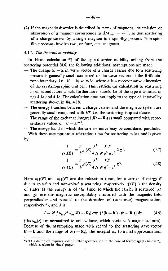
-46
(2) If the magnetic disorder is described in terms of magnons, the emission or absorption of a magnon corresponds to L1M101a1 = ± I, so that scattering of a charge carrier by a single magnon is a spin-flip process. Non-spinflip processes involve two, or four, etc., magnons.
4.1.2. The theoretica! mobility
In Haas' calculation 18) of the spin-disorder mobility ansmg from the scattering potential (4.6) the following additional assumptions are made.
The change k' - k in wave vector of a charge carrier due to a scattering process is generally small compared to the wave veetors at the Brilioninzone boundary, i.e. Ik' kl « nf2a, where a is a representative dirneusion of the crystallographic unit cell. This restricts the calculation to scattering in semiconductors which, furthermore, should he of the type illustrated in figs 4.la and 4.lc. The calculation does not apply to the type of intervalley scattering shown in fig. 4.Ib.
- The energy transfers between a charge carrier and the magnetic system are generally small compared with kT, i.e. the scattering is quasi-elastic.
- The range of the exchange integral J(r- R1) is small compared with representative valnes of Ik' k 1-1 •
The energy band in which the carriers move may he considered parabolic. With these assumptions a relaxation time for scattering exists and is given
by
1 n J2 kT 1 '(E) 2 (4.7)
•u(E) ;/ 4 N N g2 P.B2 x , :n; J2 kT
•tt(E) '(E) 11 t/ 4 N N g2 Jl-B2 X •
(4.8)
Here Ttt(E) and •tt(E) are the relaxation times for a carrier of energy E due to spin-flip and non-spin-flip scattering, respectively, g'(E) is the density of states at the energy E of the band to which the carrier is scattered, xl and xll are the magnetic susceptibility measured with the magnetic field perpendicular and parallel to the direction of (sublattice) magnetization, respectively *), and J is
J N f ub'k'* ubk J(r R1) exp {i (k- k'). (r- R1)} dr (4.9)
(the ubk(r) are normalized to unit volume, which contains N magnetic atoms). Because of the assumption made with regard to the scattering wave vector k' - k and the range of J(r- R1), the integral is, to a first approximation,
*} This definition requires some further specification in the case of ferromagnets below Tc, which is given in Haas' paper.
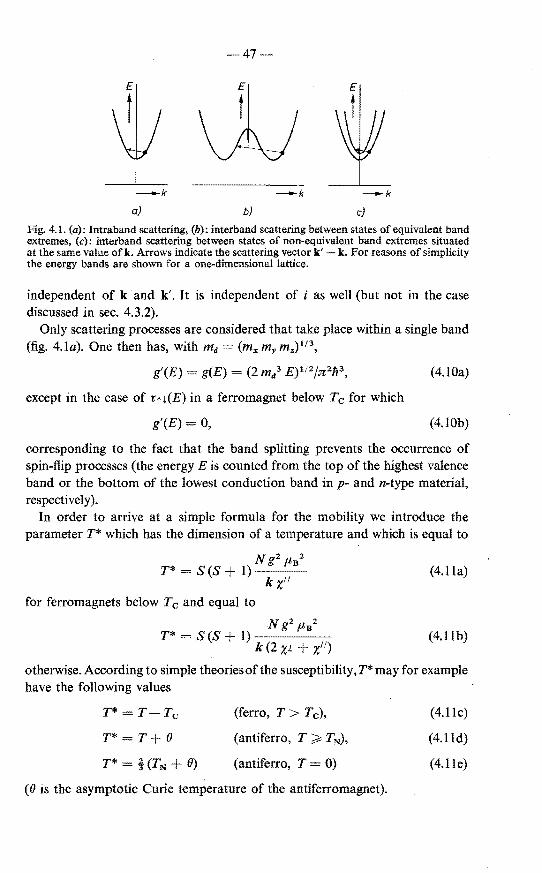
47
-k -k
a) b) c)
Fig. 4.1. (a): Intraband scattering, (b): interband scattering between states of equivalent band extremes, (c): interband scattering between states of non-equivalent band extremes situated at the same value ofk. Arrows indicate the scattering vector k' k. For reasans of simplicity the energy bands are shown for a one-dimensional lattice.
independent of k and k'. It is independent of i as well (but not in the case discussed in sec. 4.3.2).
Only scattering processes are considered that take place within a single band (fig. 4.Ia). One then has, with md = (mx my mz) 113
,
g'(E) g(E) = (2 m/ E)112jn21t3, (4.10a)
except in the case of -rn(E) in a ferromagnet below Tc for which
g'(E) 0, (4.10b)
corresponding to the fact that the band splitting prevents the occurrence of spin-flip processes (the energy Eis counted from the top of the highest valenee band or the bottorn of the lowest conduction band in p- and n-type material, respectively ).
In order to arrive at a simpte formula for the mobility we introduce the parameter T* which has the dimension of a temperature and which is equal to
Ng2 !" 2
T* = S(S + 1) B
k x" (4.11a)
for ferromagnets below Tc and equal to
N gz !" 2
T* = S(S + 1) B
k (2 x1 +x") (4.llb)
otherwise. According to simpte theoriesof the susceptibility,T* may for example have the following values
T* T Tc
T* T+ 0
T* HTN + 0)
(ferro, T > Tc),
(antiferro, T ~ TN),
(antiferro, T = 0)
(0 is the asymptotic Curie temperature of the antiferromagnet).
(4.llc)
(4.lld)
(4.lle)

48
Por obtaining an expression valid for arbitrary degeneracy of the carrier system (cf. sec. 3.1.2) we define another temperature, T', according to
9n kT' - [E- 112]- 2 {fo(1})/f112(rJ)}- 2 kT, (4.12)
16
R:>kT (non-deg.), (4.12a)
9 n 9 n h2 (3 n 2 p )213
R:> EF = (deg.), (4.12b) 16 16 2 md
where p is the carrier concentration and [ ] denotes the usual average in the case of Fermi-Dirac statistics.
With the above expressions the mobility in a direction i = x,y,z becomes
[<(E)] 8 (2 n)112
e h4
N ( T* ) (-1-)112
3 m1 m/12 J2 S (S + I) T kT' (4.13a)
e
10·3.1022
N 1 ( T*) (300)112
m, m/'2fmoS!2 J2 S (S + 1) T T cm2/V s(4.13b)
(N in cm- 3 , J in eV). These equations contain two temperature-dependent factors, T*/T and 1/T'. The former, T*/T, is shown by the curves labelled 1 in fig. 4.2. These curves were calculated with molecular-field expressions for
T'PT
1
Fig. 4.2. The temperature dependenee ofthe function T* fT in eqs (4.13a) and (4.13b). Curves I: calculated according to Haas' theory from eqs (4.11a) and (4.11 b) for S 5/2. Curves 2: calculated from eqs (4.17a) and (4.17b) forS= 5/2. For the antiferromagnetic semiconductor the asymptotic Curie temperature is taken to be twice the Néel temperature. Curves labelled l t .j, and 1 t t correspond to spin-flip scattering and non-spin-flip scattering separately.

49-
(300/T '/2 r-r-r,-rrrr-----,---,---,--,.--,-...,....,...,..,
• I 3
Fig. 4.3. The temperature dependenee of the function (300/T')1'2 in eq. (4.13b) indicating
the effect of degeneracy. Numbers labelling the curves are values of p/Nv(300), where Nv(300) = 2·5.1019 (m/m0 ) 312 cm- 3 is the effective density of states at 300 °K. Dots refer to the temperature where p = Nv(T).
the susceptibilities using in x'' below Tc and TN the Brillouin functions for S = 5j2, and in the case of the antiferromagnet e 2 TN. Figure 4.3 shows the temperature dependenee of (300fT') forsome values of p/2·5.1 019 (mafm0) 312 •
Other consequences of Haas' calculation are the following. According to eq. (4.10a) the relaxation times are proportional to E-112. It
follows that the scattering parameter r, defined by l(E) oc E 112 r(E) oc E', is equal to zero. As remarked in sec. 3.1.2 the knowledge of this value is of importance for calculating the electronic con tribution of the Seebeck coefficient.
1t is seen also that the relaxation times are isotropic, i.e. they do not depend on the directions of k and k'. This implies that, as shown also by eqs (4.13), any anisotropy in the mobility can only he due to an anisotropic effective mass.
4.1.3. Additional remarks
The susceptibility occurs in eqs (4.7) and (4.8) because in the calculation of transition probabilities double sums arise of the form
~ ~ (Sn i Sm1) exp {i q. (Rn- Rm)} (4.14a) n m
(i,j = x,y,z; q = k'- k) which are equal to 60)
kT 2 2 xii(q),
g ftB (4.l4b)
xii(q) being a generalized susceptibility. For small values of q this susceptibility can he expanded as
(4.15)
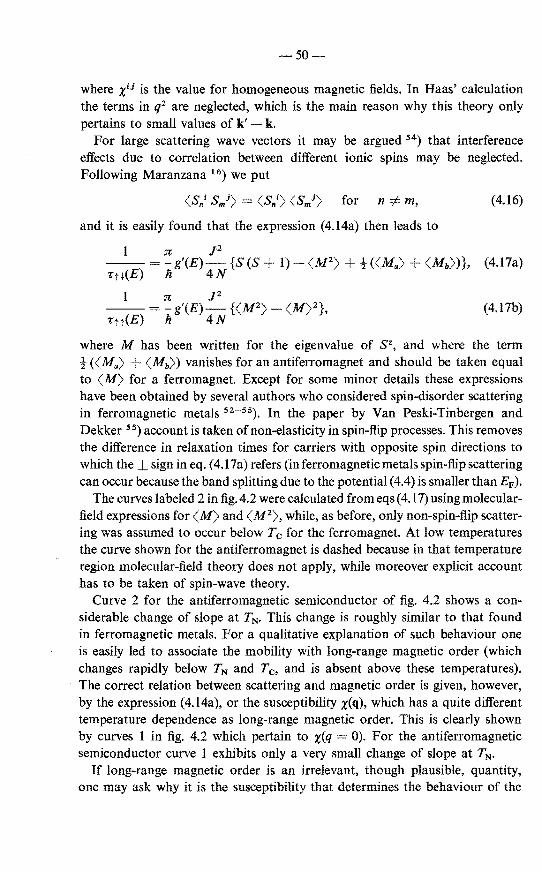
-50-
where x1J is the value for homogeneous magnetic fields. In Haas' calculation the terms in q2 are neglected, which is the main reason why this theory only pertains to small values of k' k.
For large scattering wave veetors it may be argued 54) that interference effects due to correlation between different ionic spins may be neglected. Following Maranzana 16) we put
(Sn1 SmJ) (Sn1) (Sm1) for n =F m, (4.16)
and it is easily found that the expression (4.14a) then leads to
I n P --=- g'(E) {S (S + 1)- (M2
) ± -t ((Ma)+ (Mb))}, (4.l7a) rn(E) h 4N
(4.17b)
where M has been written for the eigenvalue of sz, and where the term ! ((Ma) +(Mb)) vanishes for an antiferromagnet and should be taken equal to (M) for a ferromagnet. Except for some minor details these expressions have been obtained by several authors who considered spin-disorder scattering in ferromagnetic metals 52- 55). In the paper by Van Peski-Tinbergen and Dekker 55) account is taken of non-elasticity in spin-flip processes. This removes the difference in relaxation times for carriers with opposite spin directions to which the sign in eq. ( 4.17a) refers (in ferromagnetic metals spin-flip scattering can occur because the band splitting due to the potential ( 4.4) is smaller than EF).
The curves labeled 2 in fig. 4.2 we re calculated from eqs ( 4.17) using molecularfield expressions for (M) and (M2), while, as before, only non-spin-flip scattering was assumed to occur below Tc for the ferromagnet. At low temperatures the curve shown for the antiferromagnet is dashed because in that temperature region molecular-field theory does not apply, while moreover explicit account has to be taken of spin-wave theory.
Curve 2 for the antiferromagnetic semiconductor of fig. 4.2 shows a considerable change of slope at TN. This change is roughly similar to that found in ferromagnetic metals. For a qualitative explanation of such behaviour one is easily led to associate the mobility with long-range magnetic order (which changes rapidly below TN and Tc, and is absent above these temperatures). The correct relation between scattering and magnetic order is given, however, by the expression (4.14a), or the susceptibility x(q), which has a quite different temperature dependenee as long-range magnetic order. This is clearly shown by curves 1 in fig. 4.2 which pertain to x(q = 0). For the antiferromagnetic semiconductor curve 1 exhibits only a very small change of slope at TN.
If long-range magnetic order is an irrelevant, though plausible, quantity, one may ask why it is the susceptibility that determines the behaviour of the

-51
mobility. Perhaps one might reason as follows. According to the term s • 8 1
in the interaction (4.3), the spin of a carrier acts on the magnetic system in a similar way as a magnetic field, and the ease with which it can create a disturbanee in the magnetic system is proportional to the suseeptibility. The creation of a disturbanee means, however, that the carrier is scattered. In this way there is a direct proportionality between scattering probability and suseeptibility.
A more detailed description is needed to explain that it is rather x(q) that counts than x(k).
4.2. Comparison with the experimental mobility in MnTe
It has already been mentioned that Haas' theory leads to a small change of slope at TN in the mobility vs temperature curve. A much larger change is found experimentally for p-type MnTe. This is clearly demonstrated in fig. 4.4, which shows the temperature dependenee of both the theoretica} curve and some curves of experimental mobilities (see sec. 3.4).
That there is also a difference in temperature dependenee at low temperatures may be due to the presenee of other scattering mechanisms or, in particular for the undoped samples, to unreliable results of the Hall measurements because of imperfect crystalline quality (cf. sec. 3.4). These may also be reasoos that degenera te samples (1 to 3) seem to have higher mobilities than non-degenerate samples (4 to 8), while according to fig. 4.3 theory prediets the opposite.
2
i , , I
' r-~2 ,l. ..... ,l -~I::N~ I
~-~,"-~, ~I ·~~ [\ i \ [\
~-:.
,. 1-J. . 1\' . I Theory \
I . \
50
70
5
l\
i
-~ 2-...
I ., 1., 0·5
0·2 0·5 2 -T/TN
Fig. 4.4. Theoretica} and experimental curves of the rnobility norrnalized a T N 307 °K.

52-
The temperature-dependent anisotropy of the mobility, as shown in fig. 3.10 poses another problem. Withanisotropic relaxation time an anisotropic mobility can only be due to an anisotropic effective mass. At low temperatures we have in deed ft 1 ; ft/I R:;; 0·3 which is roughly equal to m11 /m 1 R:;; 0·25 as determined from optica} measurements 21 ). At temperatures near and above TN, on the other hand, ft1!ftu R:;; I. This may indicate that m1 and m11 depend on temperature, or, more specifically, on the magnetic order. That such a dependenee is not a priori impossible is discussed in sec. 4.3.2. Other mechanisms which may have to be considered are discussed in sec. 4.3.1.
4.3. Possible improvements of the theory
4.3.1. Various mechanisms
Beside mechanisms which the theory discussed in the foregoing has not taken into account and whose incorporation may result in a better agreement with experiment, there are also a number which might at first sight seem relevant, but are not so. Some examples of the latter are discussed first.
It has been mentioned already in sec. 4.1.1 that antiferromagnetic order can give rise to a new Brillauin-zone boundary along which an energy gap could be created, but that this does not occur in MnTe.
The theory given does not apply to inelastic scattering. The condition of elastic scattering is more readily satisfied in semiconductors than in metals (cf. sec. 4.4.2), and in the latter case it has been shown 54
•55
) that for simple ferromagnets quasi-elastic scattering obtains at temperatures near and above Tc. In antiferromagnets one might perhaps have the complication of the presenee of "optica[" magnetic excitations (at low temperatures: optical magnons), which could give rise to inelastic scattering and, possibly, toa behaviour of the· mobility as observed in MnTe. In simple two-sublattiee antiferromagnets such as MnTe there are two branches of magnon states which are, however, bothof the acoustical type (cf. ref. 57, p. 60).
Comparison of the two curves of -r(E) for antiferromagnets in fig. 4.2 shows that intervalley scattering of the type indicated in fig. 4.lb can give rise to a mobility with a sharper change of slope at TN. Since the (density-of-states) effective mass derived from the Seebeck coefficient is not larger than the optically determined effective mass(cf. sec. 3.3)the existence of different equivalent maxima in the valenee band of MnTe seems unlikely.
Having excluded the above possibilities one may consider the invalidity of one or more of the assumptions made.
The use of perturbation theory is strictly permitted only if the uneertainty in energy AE hf-r connected with the finite time -r between scattering events is less than kT (see e.g. ref. 58, p. 212). In terms of the mobility this condition reads

-53-
300 m0 ,u> 44 - cm2/V s,
T m (4.18)
which is clearly violated by the experimental mobility, especially near and above TN (cf. fig. 3.8). This may indicate that at these temperatures a magnetic analogue of the large polaron is a more appropriate starting point for theoretica! interpretation 61
).
The form of the exchange interaction ( 4.3) may be too simple in the case of MnTe. Assuming a valenee band made up of predominantly 5p-orbitals of Te atoms, we have to do with p-electrons (or holes). The angular momenturn of such electrous may also contribute to the exchange interaction *). In order to account for the observed anisotropy in the resistivity, the relaxation time due to this interaction should be an anisotropic function of the wave vector k, the anisotropy depending on temperature.
The other assumptions made in conneetion with eq. (4.3) would seem of minor importance. This is also the case as regards the neglect of the dependenee of J and x on k' k (eqs (4.9) and (4.15)).
4.3.2. Magnetization-dependent band parameters
According to eq. (4.5) antiferromagnetic order introduces a lattice-periodic potential H0AF in the crystal which is proportional to the sublattice magnetization. As is seen from its form, this potential causes a charge carrier with a given spin direction to be attracted by one sublattice and to be repulsed by the other, and the carrier will adapt its wave function accordingly. It can do so because for each ion there is another equivalent ion in the unit cell; wave functions therefore occur in pairs which in chemica! terms may belabelled as bonding and antibonding (see fig. 4.5). By forming linear combinations of these wave functions the desired adaptation can be achieved. In terms of band theory this means that in the antiferromagnetic phase H0 AF causes a mixing of states of different bands. Although for MnTe this mixing cannot give rise to a splitting of the bands (as it may do in the case of different crystallographic and magnetic unit cells, cf. sec. 4.1.1) it can change the shape of the bands and therefore also for instanee the effective mass. Since H0 AF depends on the sublattice magnetization (Sa) the temperature dependenee of such changes might be strong just below TN. It will be difficult, however, to estimate the magnitude of the effect since it will depend critically on the (unknown) band structure of MnTe.
In principle the temperature dependenee of the experimental mobility and its anisotropy would be explained if the effective mass were isotropie in the paramagnetic region, T > TN, and if m 1 (and perhaps also m11 , though less markedly) decreased with increasing sublattice magnetization in the antiferro-
*) The author is indebted to Dr C. Haas for pointing out this possibility.

-54-
Unit cell
~ I Magnetic ions
a)
b)
c)
d)
Fig. 4.5. A bonding orbital (a) and an antibonding orbital (b) can mix in such a way that the wave function of a charge carrier with a given spin direction is largerat the positions of the ions of one magnetic sublattice than at those of the other sublattice, (c) and (d).
magnetic region, T < TN. It should be noted, however, that apart from a temperature-dependent effective mass other effects arise which must also betaken into account in calculating the mobility. Temperature-dependent wave functions imply, for instance, that the exchange integral J, eq. (4.9), depends on temperature. Even more important may be the fact that with different wave functions for opposite spin directions one obtains different exchange integrals J. It can be readily shown that such different values of J lead in the expression for 1/-r(E) to additional terms which contain the "staggered" susceptibilities xl(0,0,2nfc) and x11(0,0,2nfc). These susceptibilities would be found if a spatially varying magnetic field having one direction on the one sublattice and the opposite direction on the other were applied. They are similar in magnitude and temperature dependenee to the static susceptibilities xl and xll of ferromagnets and can become very large.
Another possibility contained in the present model is that the change in shape of the bands may result in a change of acceptor-level depth. This, in turn, may lead to an anomalous temperature dependenee of the hole concentration near TN. The model of magnetization-dependent band parameters, therefore, includes the most prominent features of case (2) considered in sec. 3.3.

~55
In sec. 5.4.3 we shall come back to the question which of the proposed modifications of the theory possibly plays the major role in determining the electdeal properties of MnTe.
4.4. Magnon scattering in antiferromagnetic semiconductors
In Haas' theory the scattering probability is directly connected with the general expression for the susceptibility. This theory is independent, therefore, of the model used for the description of the magnetic system and it will be valid also in the temperature region where spin disorder should be described in termsof spin waves (magnons).
In view of the considerations on magnon drag in chapter 5 we consider in this section the ~;everse problem, viz. the question up to what temperature does magnon scattering give the correct mobility. Only the case of one-magnon scattering processes in antiferromagnets is discussed. Such processes dominate those involving two or more magnons, in any case at low temperatures (the fact that in fig. 4.2 the curve lH forspin-flip scattering lies below the curve ltt for non-spin-flip scattering agrees with this observation). Furthermore, as explained in sec. 5.2.2, the main contribution to magnon-drag effects is expected to arise from one-magnon scattering processes.
One of the conditions for the validity of Haas' theory is that the scattering may be regarded as quasi-elastic. This condition is easily formulated in the case of magnon scattering and will be treated briefly too.
4.4.1. Ca/culation of magnon scattering
We consider an antiferromagnet having N/2 magnetic ionsof one sublattice at positions Ra1 and N/2 magnetic ions of the other sublattice at (equivalent) positions Rbl· With the exchange integral J of eq. (4.9) the relevant matrix element for the scattering of a charge carrier with wave function <pk(r) and spin m, = to a state with 9'k·(r) and m, = is found to be
M M (k,+t,p; k',-!,p') (4.19)
~I (-!,p'lts- [Sa/ exp {i(k k') • Raj}+
j,! Sb/ exp {i(k-k'). Rb1}]1 +t, ,u),
where the symbol p represents the magnon system and s± sx ± iSY. For evaluating this matrix element the following expressions from the stand
ard, linear, theory of antiferromagnetic magnons are used (see e.g. ref. 57, chapter 4; a slightly different convention with regard to the sign ofthe wave veetors is used here: the creation and annihilation operators for a magnon with wave vector ±q are denoted as oe±/ or {J±/ and oc±q or {JH, respectively.)

56
( s )1/2
.Sbt+ = 2 N ~ exp (i q. Rb1). (uq {J_q + + Vq exq),
tanh 2x
yq = ~ exp (i q . 8) y -q
ó
~1 ~ a/qt2 (for small q), i=x,y,z
h w A = g flB H A•
h wq h {(we+ wA)2 - we2 yq2}112
~ h We (2 ~a/ q/)112 jf WA< 2 We~ al ql < 2 We
(4.20a)
(4.20b)
(4.2la)
(4.21 b)
(4.22)
(4.22a)
(4.23)
(4.24)
(4.25)
(4.25a)
(J12 is the exchange integral between the z nearest neighbours of a given magnetic ion to which they are connected by the veetors 8; HA is the anisotropy field; the a1 are interatomie distances multiplied by numerical constants).
When substituting (4.20a) and (4.20b) into (4.19) use can be made of the general relation
N/2
~ exp {i(k-k' + q).a1R} J=l
~2 N ~ exp {i (k-k' +q).Rb1} =- !5k•-k q+G, (4.26) 1=1 2 .
G being 2n times a fundamental vector of the reciprocallattice. In semiconductors, however, it is usually not necessary to consider Umklapp processes, i.e. scattering processes for which G =I= 0. Neglecting these one finds
J( s )1/2 M = 2 N (Uq + Vq) (tl lo:q + {J_q +I ft), (4.27)
with q k'- k. The terms in the operators o:q and fi-q + correspond, respectively, toa scattering process ofthe charge carrier in which an a: magnon with wave vector q is absorbed and one in which a {J magnon with wave vector -q is emitted. Upon squaring the matrix element one obtains
J2S M2 -- (uq + Vq)2 {nq" + (n_qtJ + 1)}.
4N (4.28)

-57-
If the magnon distribution in q-space is not significantly disturbed by the electrical current *) the occupation numbers n
11 and n_ 11 are given by the Bose
Einstein distribution, and
n11"' + n_/ + 1 = coth (I! w11/2 kT)
~ 2 k Tfli w11
for I! w11 < 2 kT,
~1 for I! w11 > 2 k T.
(4.29)
(4.29a)
(4.29b)
In conneetion with these equations it should be remarked that for I! w11 > k T
the scattering processes are not quasi-elastic so that the transport equations normally used for semiconductors cannot be applied (see next section). For the present we are interested in the high-temperature case, h w11 < k T. Here the scattering processes may be regarded as quasi-elastic, but for large values of n11
magnon theory should generally take account of higher-order terms in tx11
and {3
11, which have been omitted in eqs (4.20a) and (4.20b). Nevertheless, we shall
now make use of eq. (4.29a), on the argument that we are concerned with magnons of small wave vector and that for these the approximation of the linear magnon theory appears to be less serious than for magnons with large wave veetors (see e.g. ref. 62).
From eqs (4.2la), {4.21 b) and (4.25) we obtain
so that the squared matrix element becomes
PS w ----~--Cl_____ ____ (2 n 4 N We+ WA We Y11
11
PS 2kT ~ ----------
4 N ft (we+ WA We yJ PS kT
P kT ---2xl(T< T)
4N Ng2 f.lnz N'
(4.30)
I) (4.31)
(4.3la)
(4.3Ib)
(4.31c)
where the approximation (4.29a) is introduced in (4.31a), where in (4.31b) the terms WA and We~ a,2
q12 have been neglected WÎth respect tO We, and Where
in (4.3lc) use bas been made of
*) Theviolation of this condition leads to the secoud-order drag effects described in chapter 5.

58
s (4.32)
for nearest-neighbour interaction only (xl(T < TN) represents the perpendienlar susceptibility for temperatures be1ow TN).
Because M2 does not depend on q, the relaxation time due to the scattering is given by 1/rmagnon(E) = (n/li) g(E)M 2
, and comparison with eq. (4.7) for rtt(E) shows that for the case considered
'tmaanon = 'tH for T < TN. (4.33)
This result may easily be generalized to interactions between arbitrary neighbours in a two-sublattice antiferromagnet. In that case 2 TN in eq. (4.23) is replaced by TN 8, while due to interactions within one and the same sublattice an additional term -()Je' 2: b1
2 q12 should be included in wA. If this
term and the term we 2: a12 ql are retained in eq. (4.3la), one obtains a
result which is in complete agreement with the form of the expansion of x11(q) given in eq. (4.15).
We have thus arrived at the coneinsion that in antiferromagnetic semiconductors the scattering of charge carriers by singlemagnons-described in termsof the simple, linear magnon theory -leads to the same mobility as Haas' theory up to the Néel temperature. An analogous result has been obtained for a similar problem in conneetion with neutron scattering in ferromagnets (ref. 60, p. 131 ).
4.4.2. The condition of elastic scattering
The calculation of magnon scattering as well as that of spin-disorder scattering discussed in this chapter requires that the scattering processes be regarded as quasi-elastic, i.e. that on the average they change the energy of a carrier by an amount less than k T. This condition will be briefly considered.
Assuming an energy-independent magnon velocity, eq. (4.25a), the consequences of the 1aws of conservation of energy and crysta1 momenturn are the same as for acoustical-phonon scattering. For an isotropie magnon velocity, c, and an isotropie effective mass, m, one thus finds (see e.g. ref. 63, p. 530) that a carrier of wave vector k can only be scattered by magnons with wave vector
q < qm = 2 k + m cjli. (4.34)
In non-degenerate semiconductors a "thermal" carrier has a wave vector kr (2 m k T) 112jli and its energy can at the most be changed by an amount /i c qm 2 /i c k r m c2 • Requiring that this be less than k T implies that the temperature should be higher than
(4.35)

-59-
(c in cmjs). In degenerare semiconductors, qm 2 kF m cfk~ 2 kF = 2 (3 n 2 p)113• In this case the temperature should be higher than
T0 ' 2/i c kpfk = 47- -- °K c ( p )1/3
106 101s (4.36)
(c in cmjs; p in cm- 3).
For MnTe c is 1·4.106 cm/s 21) so that T0 is 72 °K for m 0·6 m0 , while T0 ' is 260 °K for p 6.1019 cm- 3 • This shows that in highly Na-doped samples effects of inelasticity may become important. On the other hand it is known in the case of metals that large deviations from the "classical" linear temperature dependenee of the resistivity only occur at temperatures well below the Debye temperature. Since this temperature plays the same role as T0 ' in our case 64
), large effects are not expected to occur in the temperature range considered, especially if other scattering processes too occur at low temperatures.

60-
5. MAGNON DRAG
In this chapter we reconsider the magnon-drag explanation previously given for the anomalous behaviour of the Seebeck coefficient in MnTe 13•14). 1t will be seen that a detailed analysis is impossible, mainly due to the lack of sufficiently accurate mobility data. Therefore only the simplest theoretica) model will be considered, neglecting anisotropies in effective mass, mobility and magnon velocity. Nor do we discuss in any detail the difficult theoretica! question with regard to the description of magnetic excitations in terms of magnons at temperatures comparable to TN. The treatment includes, however, the "second-order" drag effects, which Zanmarchi and Haas 21 ) have used to explain optical phenomena in MnTe.
5.1. Physical description of the drag effects
The phonon- 65) and magnon-clrag 15) effects arise as a consequence of the
law of conservation of crystal momenturn for scattering processes between charge carriers and phonons or magnons. In its strict sense this law is not valid forscattering between (quasi) particles having large wave vectors, in which case Umklapp processes may occur (cf. comment to eq. (4.26)). In such processes a considerable amount of momenturn is transferred to or withdrawn from the crystal as a whole. In the following we shall consider the case of a semiconductor in which the charge carriers are scattered between states of a single band extremum (fig. 4.la). Since in that case the scattering processes only involve (quasi) particles with small wave vectors, the law of conservation of crystal momenturn obtains in its strict sense. For the quasi particles which scatter the carriers we consider magnons, but the following discussion is valid for phonons as well. Scattering by impurities will be neglected.
5.1.1. First-order effects
The drag con tribution Ild to the Peltier effect may be thought to arise in the following way 65). Due to the combined action of the electrical field and the scattering by magnons the charge carriers acquire a stationary excess amount of crystal momentum. Since crystal momenturn is conserved in the scattering processes, the magnons also acquire an excess amount of crystal momentum, i.e. they are dragged along with the carrier current. The energy flux carried by the magnon current constitutes the magnon-clrag contribution to the Peltier heat.
In the Seebeck effect the drag con tribution Sd = IldfT is due to the fact that the flow of magnons created by the temperature difference (which, in principle, contributes to the heat conduction) drags the charge carriers along, thus enhancing the carrier accumulation which already exists at the colder end of the sample due to thermodiffusion.

-61
In the first-order effects two relaxation times are of importance. First, the relaxation time -r 1 of the charge carriers characteristic of the ra te at which they loose excess momenturn to the magnons and, second, the relaxation time -r3 of the magnons characterizing the rate at which magnons dissipate excess momentum in Um.klapp processes, boundary scattering, etc. (the interpretation of -r3 is considered in more detail in sec. 5.2.2).
It will be easily understood that lid should be proportional to -r 3 /-r 1 : a large -r 3
means a long distance over which the magnons can transport excess energy, while a small -r 1 signifies a strong coupling between the carrier and magnon systems.
5. 1.2. Second-order effects
As pointed out by Sondheimer 66), the formulation of the drag problem which
considers only the processes mentioned above leads to a violation of the Kelvin relations. In order that these be satisfied account must also be taken of the scattering of magnons (phonons) by the charge carriers. The relaxation time -r 2
for the rate at which magnons loose excess momenturn to the caniers will be inversely proportional to the carrier concentration.
As a consequence of these processes it is possible that the momentum, which is transferred from a carriertoa magnon, is returned toanother carrier before it is randomized ( due to a process characterized by -r 3). This means that the scattering of charge carriers by magnons becomes less effective, so that the spin-disorder mobility is increased. Consirlering the probabilities with which the processes mentioned occur, the factor by which the mobility increases is found to be (1 + -r3 /-r2). This increase mayalso be attributed tothefact that the carriers are scattered by a magnon system which moves along with them due to the fust-order drag effect (cf. footnote in conneetion with eq. (4.29)). Effects of this kind are called second-order effects.
It can be shown that the drag contributions [Jd and sd are decreased by roughly the samefactor (1 -r3 /-r2) by which the mobility is increased. In the case of the Peltier and Seebeck coefficient the second-order effect is also called saturation effect 65).
5.2. Simplified theory
5.2.1. Basic equations
A simplified calculation of the first-order drag effects has been given by Herring 6 5). The simplification consists ofneglecting of the energy dependenee of the relaxation times. Extending this approach to the case where second-order effects are important Zanmarchi and Haas 21) have derived the following expressions for the drag contribution Sd to the Seebeck coefficient and for the mobility:
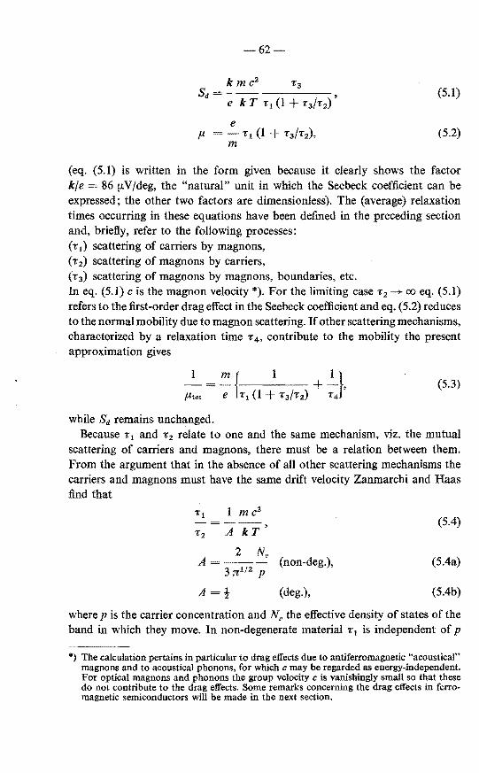
-62-
(5.1)
e (5.2)
m
(eq. (5.1) is written in the form given because it clearly shows the factor k/e = 86 ~-~oV/deg, the "natural" unit in which the Seebeck coefficient can be expressed; the other two factors are dimensionless). The (average) relaxation times occurring in these equations have been defined in the preceding section and, briefly, refer to the following processes: (T1) scattering of carriers by magnons, ( T 2) scattering of magnons by carriers, ( T 3) scattering of magnons by magnons, boundaries, etc. In eq. (5.1) cis the magnon velocity *). For the limiting case T 2 --+ oo eq. (5.1) refers to the first-order drag effect in the Seebeck coefficient and eq. (5.2) reduces to the normal mobility due to magnon scattering. If other scattering mechanisms, chamcterized by a relaxation time T 4 , contribute to the mobility the present approximation gives
1 (5.3)
#tot
while Sd remains unchanged. Because T1 and T 2 relate to one and the same mechanism, viz. the mutual
scattering of carriers and magnons, there must be a relation between them. From the argument that in the absence of all other scattering mechanisms the carriers and magnons must have the same drift velocity Zanmarchi and Haas find that
Tt 1 m c2
A kT' (5.4)
T2
2 NV A --- (non-deg.), (5.4a)
3 n112 p
A=t (deg.), (5.4b)
where p is the carrier con centration and N" the effective density of states of the band in which they move. In non-degenerate material T 1 is independent of p
*) The calculation pertains in particular to drag effects due to antiferromagnetic "acoustical" magnons and to acoustical phonons, for which c may be regarded as energy-independent. For optica! magnons and phonons the group velocity c is vanishingly small so that these do not contribate to the drag effects. Some remarks concerning the drag effects in ferromagnetic semiconductors will be made in the next section.

-63
so that 1:2 is inversely proportional to the carrier concentration, as should be expected. In degenerate material, 1:1 oc kF 1 ocp- 113 giving 1:2 ocp- 11
3•
Combining eqs (5.4), (5.4a) and (5.4b) with (5.1) and (5.2) one may write
Sa Sa0 /(1 + Sa0 /SM),
Sa0 = Sa/0- Sa! SM),
#1 = #1°/(1- Sa/SM),
2 N 0 k SM (non-deg.)
3 :n;112 p e
k
(5.5a)
(5.5b)
(5.5c)
(5.5d)
= !--. (deg.) (5.5e) e
Here Sa0 and #1° are the first-order quantities (for 1:'2 00 or SM oo), and Sa and p 1 the quantities including second-order effects. In these expressions the factor (1 + S//SM) (1- Sa!SM)- 1 reptaces the factor (1 + 1:3 /1:2 ) in eqs (5.1) and (5.2). The use of eqs (5.5b) and (5.5c) is that they permit a direct estimate to be made of the importance of second-order effects by comparing the experimental drag contribution Sa with the quantity SM. The value of the latter is a constant given by eq. (5.5e) for degenerate samples, and depends only on the carrier concentra ti on and effective density of states for non-degenerate samples. From eqs (5.5a) and (5.5b) it follows that Sa can never exceed SM (nor Sa0
) so that, for example, according to eq. (5.5e) in degenerate samples Sa can be at most !- kfe = 43 !LV /deg.
The above eqnations follow from a rather crude model based on (ill-defined) average relaxation times. Calculations in which the averaging procedures are carried out more accurately have been performed in the analogous case of phonon drag. As will be shown in sec. (5.3) these calculations result in higher values of SM (or the coefficient A of eq. (5.4)).
One correction to the value of the coefficient A is a rather trivial one. In their calculation Zanmarchi and Haas assume a single magnon branch. Usually, however, the magnon states in antiferromagnets are doubly degenerate (neglecting magnetic anisotropy). Because, according totheir calculation, the drift velocity of the magnons is inversely proportional to the number of magnons, it can be easily seen that a double degeneracy of the magnon states implies that A, and thus SM, is twice as large as given by the above equations (one may say that the more magnons there are, the more difficult it is to give them the samedrift velocity as the carriers).
5.2.2. The magnon relaxation times in antiferromagnetic and in ferromagnetic semiconductors
Herring 65•67
) has emphasized that in order to understand phonon drag in

-64-
semiconductors it is necessary to be aware of the fact that charge carriers of wave vector k can only be scattered by a pbonon having a wave vector q if q :5 2 k (cf. eq. (4.34)). In this way an electric current feeds surplus momenturn only in the low-q modes of the pbonon system. Phonon-phonon scattering next distributes the surplus momenturn over all other modes, but, in general, does not destroy it *). This is because the most probable processes between low- and high-q phonons are normal, i.e. non-Umklapp, processes in which crystal momenturn is conserved. The ultimate dissipation of crystal momenturn in the pbonon system occurs through U-processes between high-q phonons. Since, however, the relaxation time for these processes is much shorter than for the scattering of low-q by high-q phonons, it is the latter which determine the rate of lossof crystal momenturn for the low-q modes. The relaxation time r 3 for pbonon dragis thus roughly equal to the average relaxation time of the phonons with wave vector q < 2 k, where
k = kr = (2 m k T) 112/li (non-deg.),
k kF = (2 m EF) 112fli (3 n 2 p)113 (deg.)
(5.6a)
(5.6b)
are the wave veetors of a carrier of energy kT and EF, respectively. For r 1 oc k 2r-t and r 3 oc q-s-z we thus have
(5.6c)
Assuming that the same arguments apply to magnon drag, one finds that there should be a rather fundamental difference in the interpretation of r 3 for antiferromagnetic and ferromagnetic semiconductors.
As mentioned in chapter 4, in the case of antiferromagnets the larger carrier relaxation time for non-spin-flip scattering as compared with the carrier relaxation time for spin-flip scattering can be understood from the argument that the former processes involve two magnons while the latter only involve a single magnon. The dominant scattering mechanism of the carriers is, therefore, the scattering by single magnons, so that for antiferromagnets r 3 may be interpreted as the relaxation time for magnons with q :5 2 k.
In the case offerromagnets, however, the band splitting due to the magnetization prevents spin-flip scattering at temperatures up to nearly Tcand the mobility is practically determined by non-spin-flip processes, i.e. two-magnon processes. In that case the magnons taking part in the scattering of the carriers are notsubject to the condition q ;S 2 k. This means that r 3 wil be an average over all possible magnon modes which will be much smaller than the r 3 for low-q modes only.
If all other quantities involved are equal one therefore expects that r 3/r1 ,
*) Scattering of phonons (magnons) by impurities and boundaries is neglected here.

65-
and thus the first-order magnoo-drag effect, will be much smaller in ferromagnetic than in antiferromagnetic semiconductors.
With respect to secoud-order effects it is to be expected that these will be smaller for multi-magnon scattering than for one-magnon scattering. First because in the former case 1:3 will be smaller, and, second, because T 2 will be larger due to the fact that also magnons with q > 2 k have to be given the same drift velocity as the carriers (cf. the remark on the effect ofthe double degeneracy of the antiferromagnetic magnon states made at the end of sec. 5.2.1).
Another condusion to be drawn from the above observations is that in antiferromagnetic semiconductors non-spin-flip scattering contributes much less than spin-flip scattering to the first-order effects in S and to the secoud-order effects. This may be accounted for by interpreting T 1 as being due to spin-flip scattering only and including non-spin-flip scattering in the relaxation time T 4
of eq. (5.3). Except in cases of extremely large secoud-order effects this correction is of some importance only at temperatures T ~ TN since only at these temperatures are Ttt and TH of the sameorder of magnitude (see fig. 4.2).
It is finally noted that intervalley scattering between equivalent band extremes at different k-values involves magnons of large q having a small 1:3 , and is therefore expected to contribute only slightly to the drag effects.
5.2.3. Magnon drag near and above TN
Fr om the point of view of elementary theory the notion of magnons is valid only at low temperatures, while we also wish to apply the theory of magnon drag to MnTe at temperatures near and above TN. The probierus relating to magnons at high temperatures will not be discussed in this paper and the naïve point of view will be taken that for present purposes the magnon description of spin disorder is valid at all temperatures. Some support for this view is provided by the fact that neutron-scattering experiments have demonstrated the existence of magnon-like excitations at temperatures near and above TN 68
- 70), while the calculation in sec. 4.4.1 also shows that the formula derived for the mobility due to (one-) magnon processes is identical with Haas' formula relating to spin-flip scattering at temperatures up to TN. At higher temperatures the difference is only a factor (TN + B)/(T + B).
An estimate of the time of decay of a magnon with wave vector q at temperatures comparable to TN has been given by Zanmarchi and Haas 21
):
I =A q2 = l:: 2 J1 S z1 a1
2 q2 /h, (5.7) ï 3(q) i
where the J1 are exchange integrals referring to the exchange interaction between a magnetic ion and its z1 neighbours at distance a1 which all have a spin S. A similar formula (with, however, a smaller value of the ditfusion constant A) has been given by Mori and Kawasaki 71
) and by De Gennes 72).
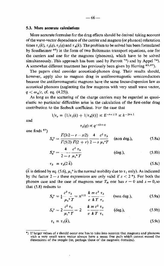
-66
5.3. More accurate calculations
More accurate formulae for the drag effects should he derived taking account ofthe wave-vector dependenee ofthe carrier and magnon (or phonon) relaxation timeST1(k), -c2(q), • 3(q) and • 4 (k). Theproblem to he solved has been formulated by Sondheimer 66) in the form of two Boltzmann transport equations, one for the carriers and one for the magnons (phonons), which have to he solved simultaneously. This approach has been used by Parrott 73
) and by Appel 74).
A somewhat different treatment has previously been given by Herring 65 •67).
The papers cited consider acoustical-phonon drag. Their results should, however, apply also to magnon drag in antiferromagnetic semiconductors because the antiferromagnetic magnons have the same linear-dispersion law as acoustical phonons (neglecting the few magnons with very small wave vector, q < wAfc, cf. eq. (4.25)).
As long as the scattering of the charge carriers may he regarded as quasielastic no partienlar difficulties arise in the calculation of the tirst-order drag contribution to the Seebeck coefficient. For the case that
and
one finds 67)
F(3J2- r sJ2) 4 c2 -c3
F(5/2) F(2 + r) 2 s p,1°T
4 c2 T3 sao= --
2- S ftlo T
. 'f3 =: T3(Û()
(non deg.), (5.8a)
(deg.), (5.8b)
(5.8c)
(kis de:fined by eq. (5.6), p, 1 ° is the normal mobility due to • 1 only). As indicated by the factor 2 s these expressions are only valid if s < 2 *). For both the pbonon case and the case of magnons near TN one has r = 0 and s = 0, so that (5.8) reduces to
c2 • 3 km c2 r 3
Sa<> = :! = ::rr;l/2 --3 p, 1°T e kT r 1
(non deg.), (5.9a)
c2 r3 km c2 T3 S/=2-- 2
ft1°T e kT r1 (deg.), (5.9b)
•1 = r1(k), (5.9c)
*) If larger valnes of s should occur one has to take into account that magnons and phonons with a very small wave vector always have a mean free path which cannot exceed the dimensions of the sample (or, perhaps those of the magnetic domains).

-67-
the first-order mobility p,1 o being given by
4 e fllo = -3 l/2- Tl
:n m
e /l1°=-T1
m
(non deg.), (5.10a)
(deg.). (5.10b)
Taking into account that the T3 in the present formulae is a factor of 4 smaller than the T3 used by Zanmarchi and Haas 21), who put T3 = T3(k), the value of Sd predicted by eqs (5.9a) and (5.9b) is about 40% of that predicted by eq. (5.1) (with T 2 = oo).
The problem of calculating the second-order effects is much more complicated than that of the first-order effects. In the papers cited only partial solutions with a limited range of validity were obtained.
For a small second-order effect and T1(k) oc k-I, T4 = oo, T3(q) oc q- 2,
Parrott 73) finds a relative change in the mobility of non-degenerate material
fl1- fl1° p m C2 T3 0·48 p Sd0
---=0·48---=---fll0 Nv kT T1 :n112 Nv kje
(5.11)
With the same approximations one finds from his equation 58 a relative change in the drag contribution to the Seebeck coefficient
sdo- sd p sdo ----=!--,
sd NV k/e (5.12a)
which is equivalent to
Nv SM = 2- (k/e), (5.12b)
p
SM being defined by eq. (5.5a). It may be noted that eqs (5.5c) and (5.11) lead to a different value of SM. In the limit of high saturation, however, eqs (5.5a) and (5.5c) must have the same SM.
In his conference paper 65) Herring quotes an equation, also valid for small
second-order effects and non-degenerate statistics, which corresponds to
Nv SM = :n112 - (kfe).
p (5.13)
This is very nearly the same result as (5.12b). In his other paper (1954b) Herring treats the case that Te~ T4 (k) is independent of k *) while T1(k) oc k- 1 and
*) The condition r 1 > r 4 is implied by the replacement of {1 •• by {1./ 0> in eq. 53 ofthe paper cited, which corresponds to neglecting thesecond-order effect on the carrier distribution.

68
r 3(q) oc q- 2 • His result for non-degenerate statistics is presented in graphical fonn and shows that the numerical coef:ficient in eq. (5.13) increases gradually with increasing importance of the second-order effect. At Sd/Sdo = 0·1, for example, one has approximately
N. SM= 7 (kfe). (5.14)
p
The paper also gives an explicit expression for Sd/ Si valid for complete degeneracy and the same conditions regarding the relaxation times as above,
(5.15a)
which is equivalent to
1 (5.15b)
with I ~M < 4/3 for 0 ~ ~ < oo. The parameter ~ in these equations may be written as
(5.15c)
where fis the fraction due to r 1 of the total loss of momenturn of the charge carriers and neglecting second-order effects. Since f R::> 1: 4 /r 1 and Te R::> 1:4 these equations give
SM = (1 to 4/3) (kfe). (5.16)
This result can also be obtained from the considerations on phonon drag in metals by Ziman (ref. 58, p. 409). He finds SM= n 2 Cdekp3 , CL being the pbonon heat capacity. Assuming that only phonons with wave vector q 2 kp contribute to CL it is easily shown that at high temperatures this leads to SM= (4/3) (kfe) per (acoustical) pbonon branch. At lower temperatures, viz. T < T0 ' 2 hckpfk (cf. eq. (4.36)), the heat capacity of the relevant phonons decreases as D(T/T0 ')/D(oo), D(x) being the well-known Debye function for the specific heat. At these temperatures one therefore expects
D(T/T0 ') k
~ D(oo) ; (5.17)
in degenerate samples. Towards lower temperatures this correction slowly decreases SM to half of its original value at T R::> 0·25 T0 '; at still lower temperatures SM diminishes more rapidly.

-69-
lt is noted that a similar quanturn correction should be applied for the tirstorder effect. Such correction might be of the form G(T/T0 ') D(T/T0')/D(oo), the first factor being the Grüneisen function (e/T)/(e/T)oo and descrihing the decrease of the coupling between caniers and phonons (i.e. an increase of r 1),
and the secoud factor taking account of the deercase in heat capacity of the phonon system. As these corrections are not very important in the cases to be considered we have not investigated whether or not this argument is too simple.
Appel 74) has considered the problem of second-order effects for combined phonon and ionized-impurity scattering of the carriers and a q-independent relaxation time of the phonons. This is a somewhat peculiar case because it is only due to the presence of impurity scattering that some of the relevant integrats remain finite. Because of this special feature it is doubtful whether the results of the calculations have a more general validity, and we have not analyzed them.
5.4. Magnon dragin MnTe
5.4.1. General remarks
As mentioneJ in sec. 3, 1.1, only few measurements of the Seebeck coefficient in MnTe have been made. Especially in view of the shape of the S(T) curve near TN we did an accurate measurement on an Na-doped sample, theresultofwhich agrees very well with that obtained by others on similarly doped samples (see fig. 3.2). Below we shall consider this (degenerate) sample as well as the four (degenerate and non-degenerate) samples reported by Milier 6) (fig. 3.3). The temperature dependenee of the resistivity of these samples agrees with that of our samples of comparable resistivity.
The separation of the Secbeek coefficient of the samples into contributions from the purely dectronie effect and the drag effect is hampered by two circumstances. In the first place, our "experimental" mobility curves (fig. 3.8) provide no reliable data on the value of the mobility which is necessary in order to evaluate the hole concentration in Miller's samples from their resistivity. In the secoud place, especially near TN, the temperature dependenee ofthe experimental mobility deviates considerably from that predicted by Haas' theory of spindisorder scattering. In sec. 4.3 we have proposed some possible explanations for this deviation. Each of these may affect the value of Se at temperatures near and above TN in some way or another, perhaps even to the extent that they are responsible for the larger part of the anomaly in S near TN. Por the moment, however, it will be assumed this is not the case and that the electronic contribution Se may be calculated from eq. (3.3) with temperature-independent effective mass and scattering parameter, and that the "experimental" mobilities

-70-
[.Nideg I [.Nideg
1600
~ 1'00 400 I 400
?=I 200 200
w 00 I
00 100 200 300
a) --rroKJ
b)
Fig. 5.1. The Seebeck coefficient of a non-degenerate sample (sample a from fig. 3.3); (a) measured Seebeck coefficient S, and calculated electronk contribution S., (b) drag contribution Sd =S-S., and maximum drag contribution SM calculated using eq. (5.18a). For the curves labelled 1 the hole concentration was derived from the resistivity of the sample and the experimental mobility of samples 4 and 8 in fig. 3.8. For the curves labelled 2 a mobility was used having a value of 100 cm2 /V s at 77 °K and the temperature dependenee of the experimental mobility ofNa-doped samples. For comparison curve 3 of fig. 5.2b is also shown.
750
Fig. 5.2. The Seebeck coefficient of our Na-doped sample (see fig. 3.2); (a) measured Seebeck coefficient S, and calculated electronk contribution s., (b) drag contribution Sd = S-s., and maximum drag contribution SM calculated using eq. (5.18b). For curves 3 and 4 the hole concentration is 17.1019 cm- 3 and 33.1019 cm- 3 , respectively, assuming r = 0 and m = 0·6m0 •
defined in sec. 3.4 may be used to convert resistivities into hole concentrations. These are the assumptions of case (1) considered in sec. 3.1.3.
Figures 5.1a and 5.2a show the experimental Seebeck coefficient Sof a nondegenerate and a degenerate sample, and some possible electronic contribu-

-71-
tions Se· For the non-degenerate sample, curve 1 for Se was obtained from the resistivity of the sample and the experimental mobility of samples 4 and 8 (fig. 3.8). This mobility is 30 cm2 /V s at 77 °K. Curve 2 for Se was obtained with a mobility having a value of 100 cm2/V s at 77 °K and the temperature dependenee as found in Na-doped samples. For the degenerate sample Se was calculated with two different temperature-independent carrier concentrations. The difference S- Se is shown in figs 5.1b and 5.2b and presumably represents the magnon-drag contribution sd.
F or a qualitative discussion of these curves we note first of all that the theory requires that Sd should be inversely proportional to the mobility. This gives a direct conneetion between the change of slope of Sa(T) and that of the mobility at TN.
A striking difference between figs 5.lb and 5.2b is that towards lower temperatures Sd increases strongly in the non-degenerate sample while this is not the case in the degenerate sample. This difference is due to the fact that T 3(2 k)/T 1 (k) depends on temperature, k being equal to kr = (2 m k T)112 /ft for non-degenerate samples, whereas for degenerate samples k = kF (3 n 2 p)113 is independent of temperature.
As follows from the correction factor (l SdfSM) in eqs (5.5b) and (5.5c), second-order effects become important if the drag contribution Sd comes close to the quantity SM. Assuming eqs (5.12b) and (5.17) tobevalid and taking the double degeneracy of the magnon states into account, we have
Nv SM= 4-(kM
p
D(T'/T. ') SM ~ 0
(kfe) 3 D(oo)
(non-deg.), (5.18a)
(deg.). (5.18b)
These estimates are indicated in figs .5.1b and 5.2b. They show that secoudorder effects should indeed be considered.
5.4.2. Drag effects at 77 °K
We fust consider the situation at low temperatures. Figures 5.lb and 5.2b show that at low temperatures sd remains well below SM for the degenerate sample, but that for curves labelled 1 of the non-degenerate sample Sd considerably exceeds SM. The latter cannot be correct. Either we have to take into account that for large second-order effects the numerical constant in eq. (5.18a) may be considerably larger than assumed (as in the case considered by Herring, eq. (5.14)), or we have used too small a mobility in calculating Se (fora given resistîvity a larger mobility means a smaller carrier concentration, a larger Se, a smaller Sd, and a higher SM)· The second possibility may be assumed to be

-72
the case because sd shows no tendency to follow the temperature dependenee of SM towards lower temperatures.
Curves labelled 2 represent the case of a larger assumed mobility and, indeed, does not show the contradiction S4 >SM. From this curve we find at 77 oK that Sd = 350 !LV/deg and SM 650 !LV/deg. Using eq. (5.5b) this gives S/ = 760 !LV /deg. If the mobility is entirely due to magnon scattering, the first-order mobility calculated according to eq. (5.11) becomes p 1° = 60 cm2 /V s. Substituting these values and c 1·4.106 cm/s 21 ) in eqs (5.9a) and (5.9b) we obtain r 3 13.10- 13 s. If, however, other scattering mechanisms determine the mobility at 77 °K, then p 1° and thus r 3 may be considerably larger. To establish a more accurate value of T 3 and its temperature dependenee it will be necessary to have more information on the mobility and the scattering prevailing at low temperatures.
In the preceding section the different temperature dependenee of Sd at low temperatures in degenerate and non-degenera te samples was attributed to the different temperature dependenee of r 3(2 k)/r1(k) for the two cases. For the strongly degenerate sample d of fig. 3.3 (see also fig. 3.2) it is found that Sd = sdo ~ 15 !LV/deg at 77 °K, which seems extremely low compared to the estimate S/ = 760 !LV /deg for the non-degenerate sample considered in fig. 5.1. The differenèe may, however, be understood by noting that at 77 °K with m = 0·6 m0 and p [Na]= 2.1020 cm- 3 (or p 90 cm/V s) one has kF!kT = 5·6. The ratio 760/15 = 51 is, therefore, more than accounted for if S/ rx f- 2 · 5 • This implies that the scattering parametersrand s for caniers and magnons satisfy 2r + s 1·5 (cf. eq. (5.6c); r 1(k) rx P'-1, r 3(q) rx q-•- 2). This relation requires no values of r and s which are a priori impossibie *).
5.4.3. Drag effects near TN
At temperatures near TN second-order effectsneed notbetaken into account for non-degenerate samples because Sd «SM. In view of the uncertainties mentioned in sec. 5.4.1 the first-order drag contribution at 320 °K (i.e. just above TN) bas been analyzed in the following general way. Figure 5.3 shows the Seebeck coefficient and resistivity at 320 °K of the four samples of fig. 3.3. According to the figure the relation between S and e may be written as
S = (k/e) In (e/eo) = l98logw(e/eo) !LV/deg,
(Jo~ 1·5.10- 3 Q cm.
(5.20a)
(5.20b)
Denoting by Pt and p 1 the total (drift) mobility and mobility due to one-
*) In the calculation of • 3 above it was assumed that r s 0. Other values of r and s do not, however, change the results very much, except if s would be 2 or larger, cf. eqs (5.8a) and (5.8b).

600 s (!JV/deg)
1 500
1001-
. ~
73-
5 10-2 2 5 10-1 2 5 I -fl(JJ.cm)
Fig. 5.3. Seebeck coefficient vs resistivity at 320 °K for samples a, b, c and d of fig. 3.3. The arrow indicates the value 1·5.10- 3 fl cm for eo in eq. (5.20).
magnon scattering, respectively, one also bas for non-degenerate statistics, negligible second-order effects and r 3 given by eq. (5.7),
k h [r + 2 + In (Nv ltr e e)] + ·
e A 6p,1 m kT2 (5.21)
From the theoretica! point of view the quantity of main interest is c2 /A. The value of this quantity and that of Sd are now determined.
Combiningeqs (5.20a) and (5.21), one obtains, putting x= ltr (T/300)3'2 and
m5 = m e2, 13 (cf. eq. (3.5b)): k
Sd = In (e2 +r Nv !tr e eo)- 1
e
A
k 3·36.10- 2/eo -In , e x (m5fm0 )312
6p,1 m(kT)2
-----ln(e2 +r Nu en )- 1 h2 e v rt r:o
5·25.1012 e-2r/3/-t1 (_!_)1/2 x ms In 3·36.10-2/eo , #r 300 m0 x (m5fm0 )
3'
2
(5.22)
(5.23)
with x in cm2/V s, eo in n cm, c2/A in s- 1 • Figures 5.4a and b show StJ and y = {exp (2 r/3)} (3p,1/2 p,1) (300/T)1' 2 (c2/A) as a function of x for f!o = 1·5.10- 3 0 cm and different relevant values of m5 • From these figures Sd and {exp (2 r/3)} (3p,r/2p,1) (c2/A) are directly evaluated once #r and m5 are known. They also show the effect of changing the assumed values of ltr and

-74
Fig. 5.4. (a) The drag contribution 8 4 and (b) the quantity Y = (3/2) 5·25.1012 x (m5 /m0 ) 1n {22 x- 1 (ms/m0)- 312 }
as a function of x = ftt (T/300) 312 for various values of m5 = m exp (2 r/3) acording to eqs (5.22) and (5.23) with eo 1·5.10- 3 n cm. Arrows indicate combinations of values of x and ms for which x (ms/m0 ) 312 22 cm2/V s.
Milier 6 ) finds frorn the resistivity of samples of cornposition NaöMn1 -öTe a rnobility of about 2 crn2/V s at 320 oK (assurning that at this ternperature the hole concentration is equal top [Na]= 2 ó.l022 crn- 3
). A rnobility of 4 crn2/V s seerns a reasonable cornprornise between this value and our highest experirnental rnobility of 7 crn2/V s at 320 oK (see fig. 3.8). With x 4·5 crn2/V s and ms = 0·6 m0 figs 5.4a and b give S11 R::: 200 [.LV/deg and {exp (2 r/3) }{3 p,/2 p 1)(c2JA) ~ 5.1013 s- 1
•
Assurning that Haas' theory of spin-disorder scattering is valid, r 0 and 2 ,ud3 p, = I (assurning that only spin-flip scattering contrib"!ltes to the drag effect) so that c2 /A = 5.1013 s- 1 • The theoretica! value calculated according

-75-
to eq. (5.7) with exchange integrals quoted by Zanmarchi and Haas 21) is 1·1.1013 s- 1 . As remarked in conneetion with eq. (5.7) other authors 71 •72)
obtain somewhat smaller values of A than Zanmarchi and Haas. Our experimental value of 5.1013 s- 1 for c2/A thus appears to he in quite satisfactory agreement with theory.
lt will he noted that according to fig. 5.4b the value of c2 /A is fairly insensitive to variations in mobility and Seebeck effective mass as long as x (m5fm0 ) 312 ;S 15 cm2 /V s. There is therefore a certain freedom in changing the assumed values of f.lt and m5 without coming into conflict with the theoretica} value of c2 /A.
For a qualitative discussion of the temperature dependenee of c2 /A near TN it is remarked that towards lower temperatures the quantity x increases roughly as the ratio of the experimental mobility to the theoretica} mobility in fig. 4.4. Above TN the mobility in non-degenerate material is not accurately known, but it seems likely that at these temperatures x is roughly constant. Because, as just mentioned, c2 /A is only a weak function of x and, furthermore, f!o is constantforT > 240 °K (fig. 3.3), it follows that c2 /A is roughly constant for T > TN and increases only slightly towards lower temperatures. A pronounced change of c2 /A with temperature near TN is not expected 21).
We now consider degenerate samples, like the sample of fig. 5.2 and sample d of figs 3.3 and 5.3. As the latter two figures show, the resistivity and Seebeck coefficient of degenerate samples ohey the same relations (5.20a) and (5.20b) as non-degenerate samples. As long as only first-order effects are considered this may he attributed to the fact that the total Seebeck coefficient Se + S4° may he rather insensitive to effects of degeneracy because these enlarge Se and reduce sdo (forT> TN we have sdo oc r3/rl oc f- 1). Figure 5.2 shows, however,
"' that for degenerate samples second-order effects cannot he neglected at tem-peratures T ~ TN. Making the appropriate correction according to eq. (5.5b) for SM= 220 !1-V/deg, one finds for curve 3 with S4 150 !1-V/deg and curve 4 with S4 = 170 !1-V/deg that S4° is 470 and 750 !1-/Vdeg, respectively. Contrary to the expectation these values are appreciably larger than the 200 !1-V /deg obtained for non-degenerate samples.
Another feature of the experimental data also disagrees with the theoretica! expectation concerning second-order effects. As mentioned in sec. 5.1.2 and as shown by eq. (5.5c), the mobility increases with increasing second-order effect. Therefore, the mobility in the degenerate sample should he larger than in a non-degenerate sampleforT;;:;:; TN. This is indeed the case (cf. fig. 3.8). However, at temperatures below TN second-order effects are negligible and both types of samples should have the same mobility (neglecting the effect of T', fig. 4.3). This should lead to only a small change of slope at TN in the mobility for the degenerate sample, as shown by the dashed curve in fig. 5.5. lnstead of a small change of slope the experimental mobility in degenerate samples shows
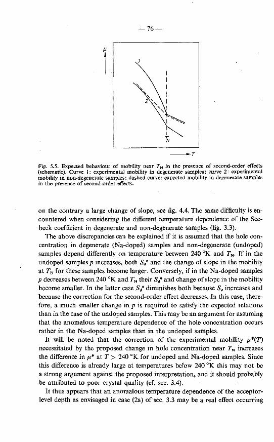
76-
-T
Fig. 5.5. Expected behaviour of mobility near T N in the presence of second-order effects (schematic). Curve 1: experimental mobility in degenerate samples; curve 2: experimental mobility in non-degenerate samples; dasbed curve: expected mobility in degenerate samples in the presence of second-order effects.
on the contrary a large change of slope, see fig. 4.4. The same difficulty is encountered when consirlering the different temperature dependenee of the Seebeck coefficient in degenerate and non-degenerate samples (fig. 3.3).
The above discrepancies can be explained if it is assumed that the hole concentration in degenerate (Na-doped) samples and non-degenerate (undoped) samples depend differently on temperature between 240 °K and TN· If in the undoped samples p increases, both sdo and the change of slope in the mobility at TN forthese samples become larger. Conversely, if in the Na-doped samples p decreases between 240 °K and TNtheir sdo and change of slope in the mobility become smaller. In the latter case Sdo diminishes both because Se increases and because the correction for thesecond-order effect decreases. In this case, therefore, a much smaller change in p is required to satisfy the expected relations than in the case ofthe undoped samples. This may be an argument for assuming that the anomalous temperature dependenee of the hole concentration occurs rather in the Na-doped samples than in the undoped samples.
It will be noted that the correction of the experimental mobility p,*(T) necessitated by the proposed change in hole concentration near TN increases the difference in p,* at T > 240 °K for undoped and Na-doped samples. Sirree this difference is already large at temperatures below 240 oK this may not be a strong argument against the proposed interpretation, and it should probably be atttibuted to poor crystal quality (cf. sec. 3.4).
It thus appears that an anomalous temperature dependenee of the acceptorlevel depth as envisaged in case (2a) of sec. 3.3 may be a real effect occurring

-77
in MnTe. As mentioned in sec. 4.3.2 such an effect is possible ifthe band parameters depend on the sublattice magnetization.
The model of magnetization-dependent band parameters also includes the possibility of a temperature-dependent effective mass (case (2b) of sec. 3.3). A temperature-dependent effective mass cannot contribute much to diminish the discrepancies discussed here, but it can contribute significantly to the temperature dependenee of Se. The proposed model need not, however, lead to a magnon-drag contribution to the Secbeek coefficient smaller than theoretically expected because of the insensitivity of c2/A to variations in effective mass and mobility.
In sec. 4.3 two other modifications in the theory of spin-disorder scattering are mentioned, viz. an interaction between charge carriers and ionic spins different from that assumed by Haas, and the possible importance of magneticpolaron effects at T ~ TN. In the former case the relaxation time determining the mobility is an anisotropic function, as yet unknown, of the wave vector k. It can he easily shown that a possibly temperature-dependent effective *) scattering parameter r cannot account for the different temperature dependenee of the resistivity and Secbeek coefficient in degenerate and non-degenerate samples. The magnetic-polaron model can account for this difference only if it also leads to a different temperature dependenee of the hole concentration in the two types of samples, or if the model includes a mechanism that corresponds to the second-order effect but works out differently.
*) Because of the anisotropy of -r(k) a true scattering parameter r defined by • a: E'- 1 12
may not exist.
-78-
6. CONCLUDING REMARKS
For temperatures below 240 °K the interpretation of the electrical transport properties of p-type MnTe seems to pose no essential problems. From a further study of the Seeheck coefficient and the dominating scattering mechanism it should be possible to obtain the value of the magnon relaxation time and its dependenee on temperature and wave vector.
The origin of the interesting transport properties above 240 oK is less clear. Starting from the simple assumptions of a temperature-independent acceptorlevel depth and effective mass, and assuming an interaction between the charge carriers and ionic spins proportional to s • S 1, as well as the validity of a simple description of magnon drag, it has been shown that the following experimental data cannot he accounted for: (A) the sharp change of slope at TN (307 °K) in the "experimental" mobility
as a function of temperature (see fig. 4.4), (B) the temperature-dependent anisotropy ttu I ft 1 ( see fig. 3.1 0), (C) the larger experimental mobility in degenerate samples than in non-de
generate samples (see fig. 3.8), (D) the different temperature dependenee of the experimental mobility (see
figs 4.4 and 5. 7) and of the Seeheck coefficient (see fig. 3.3) near TN in degenerate and non-degenerate samples,
(E) the larger drag contribution to the Seebeck coefficient at T?; TN in degenerate samples (after correction for second-order effects) than in nondegenerate samples.
Point (C) may he related to imperfect crystal quality. It seems unlikely that this is also the case for the other points listed although, of course, verification by measurements on more perfect crystals would he valuable.
In conneetion with (A) and (B) three possible modifications of the theory of spin-disorder scattering were proposed in sec. 4.3: (1) the interaction between charge carriers and ionic spins giving rise to spin
disorder scattering is of a more complex form than that assumed in eq. (4.3), this complexity being possibly due to spin-orbit coupling of the chat gt: carriers,
(2) the interaction between charge carriers and ionic spins leads not only to scattering, but also to magnetization-dependent band parameters,
(3) at T ?; TN the mean free path of the charge carriers due to the scattering is so small that a magnetic-polaron model is a better starting point for theoretica! explanations.
In case (1) no anomalous temperature dependenee of the hole concentration is expected to occur near TN and the "experimental" mobility detined in sec. 3.4 will he equal to the drift mobility (except for the trivial effect of crystal quality, and the possibility that there is an anomalous con tribution to the Hall coefficient

-79-
at low temperatures). In order to account for the observed anisotropy in the mobility, point (B), the relaxation time must be an anisotropic function, as yet unknown, of the wave vector k. It can be easily shown that point (E) requires the effective scattering parameter to be smaller than Such a change in the value of r cannot, however, account for the different temperature dependenee of the mobility and Seebeck coefficient in degenerate and non-degenerate material, point (D).
If the band parameters depend markedly on the sublattice magnetization (case (2)), the acceptor-level depth, and thus the hole concentration, may change anomalously near TN . .Due to this change the drift mobility is not equal to the "experimental" mobility. The drift mobility might still originate from the interaction (4.3), but account must be taken of temperature dependenee of the effective mass and exchange integrals J, while the mobility will also include terms containing the staggered susceptibility. This model seems to be capable of explaining all items listed, except perhaps (C). Further theoretical work is necessary to determine whether the model does in fact lead to the required temperature dependenee of the drift mobility and its anisotropy, points (A) and (B). The difficulties of points (D) and (E) would be removed if near TN and with rising temperature the hole concentration either increases in the nondegenerale (undoped) samples or decreases in the degenerate (Na-doped) samples. As remarked in sec. 5.4.3, the fact that the mobility and the effective mass may have values different from those assumed in that section need not greatly affect the experimental value of c2/A, the quantity determining the magnitude of the first-order drag effect at temperatures comparable to TN.
In tbe case of magnetic po larons both the theoretical mobility and the Seebeck coefficient have to be reconsidered completely. Point (D) requires tbat tbe model leads to a temperature-dependent acceptor-level deptb, or tbat it includes some mecbanism which corresponds to the second-order drag effect and wbich results perhaps in a polaron effective mass depending on the hole concentration.
According to tbe above considerations tbe evidence of tbe available data strongly suggests that in the case of broad-band conduction tbe transport properties of p-type MnTe are significantly affected by amagnetization-dependent effective mass and acceptor-level deptb (althougb tbe dependenee need not be as large as sbown in tigs 3.6 and 3.7).
Tbe optical data 19 - 21) are not in disagreement with tbis conclusion, but neither do they provide information regarding its validity. For experimental verification of tbe conclusion it would be of interest to find new and independent ways of measuring tbe drift mobility, hole concentration or effective mass at temperatures near TN. Tbe drift mobility could perhaps be obtained from noise measurements 75
) or witb tecbniques using injection pulses 76). In spite of its anomalous behaviour a carefut study of the Hall effect might still give infor-

-80
mation regarding the possible anomalous temperature dependenee of the hole concentration near TN. If these measurements show that points (C) and (D) are real mobility effects, a polaron model with concentration-dependent effective mass deserves serious attention.
Acknowledgement The work described in this thesis was carried out in the Philips' Research
Laboratorles in Eindhoven. I wish to express my sineere gratitude to the Directors of these laboratorles fortheir permission to proceed with this work fora much longer time than orlginally foreseen, and to present its results as a thesis.
The investigation of MnTe was started in the group of Dr H. J. Vink at the suggestion of and in collaboration with Drs C. Haas and W. Albers. The frequent discussions with Dr Haas, now Professor at the University of Groningen, have greatly infiuenced many of the ideas put forward in this work. Without the care devoted by Mr A. M. J. H. Senter to the difficult preparation ofMnTe, the results presented would not have been obtained.
I am greatly indebted to Dr W. F. Knippenberg for bis continuons encouragement durlng the writing of the manuscript. Discussions with many colleagues, in partienlar Drs W. van Haerlngen, F. E. Maranzana and G. Zanmarchi, are gratefully acknowledged. Special thanks are due to Mrs A. Meyer-Huisman for preparation of the manuscript for publication.

-81
REPERENCES 1) C. Herring, inG. T. Rado and H. Suhl (eds), Magnetism, Academie Press Jnc., New
York, 1966, Vol. 4. 2 ) S. Methfessel and D. C. Mattis, inS. Flügge and H. P.J. Wijn (eds), Hb. Phys.,
Vol. 18/1, 1968, p. 389. · 3 ) D. Adler, Solid State Phys. 21, 1, 1968. 4 ) E. Uchida, H. Kondoh and N. Fukuoka, J. phys. Soc. Japan 11, 27, 1956. 5) R. E. Frederick and C. R. Manser, U.S. Patent 2,890,260, !958. 6) R. C. Miller, in R. R. Heikes and R. W. Ure Jr. (eds), Thermoelectricity: science
and engineering, Interscience Publishers, New York, 1961, p. 92. · 7 ) H. Yadaka, T. Harada and E. Hirahara, J. phys. Soc. Japan 17, 875, 1962. 8) E. D. Deviatkova, A. V. Golubkov, E. K. Kudinov and I. A. Smirnov, Soviet
Phys. Solid State 6, 1425, 1964. 9 ) A. J. Panson and W. D. Johnston, J. inorg. nucl. Chem. 26, 705, 1964.
1 ~ W. Albers and C. Haas, Phys. Letters 8, 300, 1964. 11) W. Albers and C. Haas, Proc. int. conf. physics of semiconductors, Dunod, Paris,
1964, p. 1261. 12) W. Albers, G. van Allerand C. Haas, in Propriétés thermodynamiques, physîques
et structurales des dérivés semîmétalliques, Eds CNRS, Paris, 1967, p. 19. · 13) J. D. Wasscher and C. Haas, Phys. Letters 8, 302, 1964. 14) J. D. Wasscher, A. M. J. H. Seuter and C. Haas, Proc. int. conf. physics of semi-
conductors, Dunod, Paris, 1964, p. 1269. 15) M. Bailyn, Phys. Rev. 126, 2040. 1962, 16) F. E. Maranzana, Phys. Rev. 160, 421, 1967. 17) H. J. van Daal and A. J. Bosman, Phys. Rev. 158, 736, 1967. 18) C. Haas, Phys. Rev. 168, 531, 1968. 19) G. Zanmarchî, J. Phys. Chem. Solids 28, 2123, 1967. 20) G. Zanmarchi and C. Haas, J. appl. Phys. 39, 596, 1968. 21) G. Zanmarchi and C. Haas, Philips Res. Repts 22, 389, 1968. 22) A. M. J. H. Seuter, in Propriétés thermodynamiques, physiques et structurales des
dérivés semimétalliques, Eds CNRS, Paris, 1967, p. 459. 23
) J. D. Wasscher, Solid State Comm. 3, 169, 1965. 24) J. D. Was se her, in Propriétés thermodynarniques, physiques et structurales des dérivés
semimétalliques, Eds CNRS, Paris, 1967, p. 465. 25) K. Walther, Solid State Comm. 5, 399, 1967. 26) J. van den Boomgaard, Philips Res. Repts, to be published. 27) N. Kunitomi, Y. Hamaguchi and S. Anzai, J. Phys. Radium 25, 568, 1964. 28) S. Greenwald, Acta cryst. 6, 396, 1953. 29) K. K. Kelley, J. Am. chem. Soc. 61, 203, 1939. 3~ K. Ozawa, S. Anzai and Y. Hamaguchi, Phys. Letters 20, 132, 1966. 31) T. Komatsubara, M. Murakami and E. Hirahara, J. phys. Soc. Japan 18, 356,
1963. 32) N. N. Sirota and G. J. Makovetski, Sov. Phys. Doklady 11, 888, 1967. 33) L. J. van der Pauw, Philips Res. Repts 13, 1, 1958. 34) L. J. van der Pauw, Philips Res. Repts 16, 187, 1961. 35) D. H. Kroon, Laberatory magnets, Centrex, Eindhoven, 1967. 36) T. M. Dauphinee and E. Mooser, Rev. sci. Instr. 26, 660, 1955. 37) L. J. van der Pauw, Rev. sci. Jnstr. 31, 1189, 1960. 38) J. D. Wasscher, Philips Res. Repts 16, 301, 1961. 39) J. Hornstra and L. J. van der Pauw, J. Electron. Control 7, 169, 1959. 40) z. Nehari, Conformat mapping, McGraw-Hill, New York, 1952. 41) P.F. Byrd and M.D. Freedman, Handhook of elliptic integrals, Springer Verlag, 1954. 42) G. Bosch, J. Phys. Chem. Solids 27, 795, 1966. 43) C. Haas, A. M. J. G. van Run, P. F. Bongers and W. Albers, Solid State Comm.
5, 657, 1967. 44) E. H. Putley, The Hall effect and related phenomena, Butterworths, London, 1960. 45) J. S. Blakemore, Semiconductor statistics, Pergamon Press, Oxford, 1962. 46) H. B. G. Casimir, Rev. mod. Phys. 17, 343, 1945. 47) J. D. Wasscher, W. Albers and C. Haas, Solid-State Electronics 6, 261, 1963. 48) C. J. G. F. J anssen, Some properties of MnTe single crystals, Thesis, University of
Utrecht, 1965. 49) J. Kondo, Progr. theoret. Phys. (Kyoto) 27, 772, 1962.

-82
50) E. Callen, Phys. Rev. Letters 20, 1045, 1968. 51 ) A. Taylor, cited by R. R. Heikes in P. H. Egli (ed.), Thermoelectricity, John Wiley
and Sons, New York, 1960, p. 99. 52) T. Kasuya, Progr. theoret. Phys. (Kyoto) 16, 58, 1956. 53) T. Kasuya, Progr. theoret. Phys. (Kyoto) 22, 227, 1959. 54) P. G. de Gennes and J. Friedel, J. Phys. Chem. Solids 4, 71, 1958. 55) T. van Peski-Tinbergen and A. J. Dekker, Physica 29, 917, 1963. 56) P.W. Anderson, inG. T. Rado and H. Suhl (eds), Magnetism, Academie Press lnc.,
New York, 1963, Vol. 1, p. 25. 57) C. Kittel, Quantum theory of solids, John Wiley & Sons, New York, 1963. 58) J. M. Ziman, Electroos and phonons, Ciarendon Press, Oxford, 1963. 59) D. Adler and H. Brooks, Phys. Rev. 155, 826, 1967. 60) P. G. de Gennes, inG. T. Rado and H. Suhl (eds), Magnetism, Academie Press Inc.,
New York, 1963, Vol. 3, p. 115. 61) T. Wolfram and J. Callaway, Phys. Rev. 130, 45, 1963. 62) L. R. Walker, inG. T. Rado and H. Suhl (eds), Magnetisrn, Academie Press Inc.,
New York, 1963, Vol. I, p. 229. 63) W. Shockley, Electroos and holes in semiconductors, Van Nostrand Inc., Princeton,
1950. 64) E. H. Sondheirner, Proc. phys. Soc. 65A, 561, 1952. 65) C. Herring, in Halbleiter und Phosphore, Vieweg & Sohn, Braunschweig, 1954, p. 184. 66) E. H. Sondheirner, Proc. roy. Soc. (London) 234, 391, 1956. 67
) C. Herring, Phys. Rev. 96, 1163, 1954. 68) B. Jacrot and T. Riste, in P.A. Egelstaff(ed.), Thermal neutron scattering, Academie
Press Inc., London, 1965, p. 251. 69) T. Riste, J. appl. Phys. 39, 528, 1968. 70) P. Martel, R. A. Cowley and R. W. H. Stevenson, J. appl. Phys. 39, 1116, 1968. 71) H. Mori and K. Kawasaki, Progr. theoret. Phys. (Kyoto) 27, 529, 1962. 72) P. G. de Gennes, J. Phys. Chern. Solids 4, 223, 1958. 73) J. F. Parrott, Proc. phys. Soc. 70B, 590, 1957. 74) J. Appel, z. Naturf. 13a, 386, 1958. 75) G. A. Ac ket, On the conduction mechanism of some transition-metal oxides, Thesis,
UniversityofUtrecht, 1965. See also R. J. J. Zijlstra, F. J. Leeuwerik and Th. G. M. Kleinpenning, Phys. Letters 23, 185, 1966. .
76) D. J. Gibbons and W. E. Spear, J. Phys. Chem. Solicts 27, 1917, 1966.

83
Summary
MnTe is an antiferromagnetic semiconductor with a Néel temperature TN of 307 °K and an energy gap of 1·2 eV. The electrical properties, Hall coefficient, resistivity and Seebeck coefficient (thermoelectric power) ofp-type MnTe show a marked infiuence of the rapidly changing magnetic ordering occurring near T N·
The investigation and explanation of this infiuence constitutes the main subject of this thesis.
In chapter 1 some general properties of MnTe are discussed. In chapter 2 a description is given of the experimental arrangements used, and of a simple and sensitive method for measuring anisotropies in the resistivity.
The results of the measurements are presented and their interpretation is discussed in chapter 3. It is found that a pronounced anisotropic anomalous contribution to the Hall effect occurs at temperatures above 240 °K. The sign and temperature dependenee of this contribution agrees with the predictions of Maranzana's theory descrihing the anomalous Hall effect in magnetic conductors. However, this theory does not account for the magnitude and the anisotropy of the observed effect.
Important factors for the description of the resistivity and Seebeck effect are spin-disorder scattering and magnon drag. These phenomena are discussed in chapters 4 and 5, respectively.
Disorder in the orientation of the magnetic moments causes scattering of the charge carriers due to the existence of an exchange interaction between a charge carrier and the partially filled shells of the magnetic atoms. Haas recently calculated the mobility of charge carriers in magnetic semiconductors making certain assumptions, among other things as regards the form of the interaction mentioned. It is found that this theoretica! mobility cannot account for the temperature dependenee of the resistivity observed in MnTe near TN, nor for the observed temperature dependenee of the anisotropy of the resistivity.
Three possible extensions ofthe theory of spin-disorder scatteringareindicated: (1) The true form of the interaction between charge carriers and magnetic spins is more complicated than assumed. (2) The interaction causes a mixing of states of different energy bands, the amount of mixing depending on the magnitude of the (sublattice) magnetization. This may lead to a magnetization-dependent effective mass and acceptor-level depth. (3) At temperatures T?::, TN the mobility is so small (of the order of 5 cm2 /V s) that a magneticpolaron model is a better starting point for theoretica! explanations.
In conneetion with the discussion of magnon drag a calculation is given of the mobility in antiferromagnetic semiconductors due to the scattering caused by the creation and annihilation of a magnon. The equation obtained agrees with the corresponding equation of Haas' theory at all temperatures up to TN.
At temperatures above TN the difference between the two results is only small.

-84-
In chapter 5 both fi.rst-order and second-order magnon-drag effects are discussed. The first-order drag effect appears in the Seebeck (and Peltier) effect, and is caused by the mutual drag between currents of charge carriers and magnons resulting from the scattering of charge carriers by magnons. Secoudorder effects become important if the scattering of magnons by charge carriers contributes significantly to restoring equilibrium in the magnon system. This is only the case if the carrier concentration is large. Second-order effects lead to an increased mobility of the carriers and to a decreased drag contribution to the Seebeck effect.
At low temperatures (measurements have been done down to 77 °K) the magnitude and wave-vector dependenee of the magnon relaxation time can he estimated from the drag contri bution to the Seebeck coefficient in samples with different hole concentration. For obtaining more accurate results more information is required regarding the mobility at these temperatures.
If it is assumed that in MnTe the hole concentration and effective mass do not, or do nearly not, depend on temperature, the first-order magnon-drag effect is found to account adequately for the observed Seebeck coefficient at temperatures near and above TN. From the measurements the ditfusion constant of the magnons can be derived. The value obtained is relatively insensitive to variations in the assumed values of effective mass and mobility, and it agrees fairly well with theoretica! expectation.
It is shown that at temperatures close to and above TN second-order effects should be important in highly-Na-doped samples, which have a large hole concentration. From this fact a different temperature dependenee is expected to occur in the resistivity and Seebeck coefficient of undoped and Na-doped samples. The observed difference is, however, opposite to th~t expected. It is concluded that probably the Na-acceptor-level depth depends on the sublattice magnetization. Also a refined magnetic-polaron model may perhaps account for the experimental data.
In the final chapter 6 the main differences between experimental data and the simple theoretica! roodels used are reviewed and compared to the theoretica! refinements proposed in chapter 4. Some suggestions for further experimental workon MnTe are made.

85-
Samenvatting
MnTe is een antiferromagnetische halfgeleider waarvan de elektrische eigenschappen duidelijk beïnvloed worden door de sterk veranderende magnetische ordening die plaats vindt rond de Néel-temperatuur, TN 307 °K. Het voornaamste onderwerp van dit proefschrift is de bestudering en verklaring van deze invloed op de elektrische weerstand, het Hall-effekt en het Seebeck-effekt (thermokracht) in p-type MnTe.
Na een bespreking van enige algemene eigenschappen van MnTe in hoofdstuk I, wordt in hoofdstuk 2 een beschrijving gegeven van de gebruikte meetmethoden. In het bijzonder wordt ingegaan op een methode om op eenvoudige en gevoelige wijze weerstandsanisotropieën te meten.
In hoofdstuk 3 worden de meetresultaten en hun mogelijke interpretaties besproken. In het Hall-effekt blijkt een sterk anisotrope anomale bijdrage op te treden bij temperaturen boven 240 °K. De temperatuurafhankelijkheid van deze bijdrage is in goede overeenstemming met Maranzana's theorie van het anomale of buitengewone Hall-effekt in magnetische geleiders. Deze theorie geeft echter geen verklaring voor de grootte en de anisotropie van het waargenomen effekt.
Belangrijk voor de beschrijving van weerstand en Seebeck-coefficient zijn spinwanorde-strooiing en magnon-drag ("magnon-meesleep-effekt"). Deze verschijnselen worden achtereenvolgens besproken in de hoofdstukken 4 en 5.
Wanorde in de orientatie van de magnetische momenten geeft aanleiding tot strooiing van ladingdragers doordat er een plaatsruil-wisselwerking is tussen een ladingdrager en de gedeeltelijk gevulde schillen van de magnetische atomen. Onder bepaalde veronderstellingen, o.a. wat betreft de vorm van genoemde wisselwerking, heeft Haas een theoretische berekening gegeven van de uit deze strooiing voortvloeiende beweeglijkheid van ladingdragers in magnetische halfgeleiders. Het verloop van deze beweeglijkheid blijkt de bij de Néel-temperatuur waargenomen temperatuurafhankelijkheid van de weerstand in p-type MnTe niet te kunnen verklaren. Ook geeft de theorie geen rekenschap van de gevonden temperatuurafhankelijkheid in de anisotropie van de weerstand.
Drie mogelijke uitbreidingen van de theorievoor spinwanorde-strooiingworden genoemd: (1) De werkelijke vorm van de wisselwerking tussen ladingdragers en magnetische spins kan gecompliceerder zijn dan in Haas' theorie wordt aangenomen. (2) De wisselwerking brengt een menging teweeg van toestanden uit verschillende energiebanden, waarbij de grootte van de menging afhangt van de subrooster-magnetisatie. Dit kan onder meer leiden tot een magnetisatieafhankelijkheid van effektieve massa en acceptordiepte. (3) De beweeglijkheid bij temperaturen T :;_:: TN is zo klein (van de orde van 5 cm2 /V s) dat een magnetisch-polaronmodel een beter uitgangspunt voor theoretische beschouwingen is.

86
In verband met de discussie van magnon-drag-verschijnselen wordt aan het eind van hoofdstuk 4 een berekening gegeven van de beweeglijkheid in antiferromagnetische halfgeleiders verO&rzaakt door strooiing ten gevolge van het creëren en annihileren van een magnon. De verkregen formule stemt in het hele temperatuurgebied totTNovereen met de overeenkomstige formule uit Haas' theorie. Bij temperaturen boven TN zijn de afwijkingen tussen de uitkomsten van de twee berekeningen slechts gering.
Bij de magnon-drag-effekten worden in hoofdstuk 5 zowel de eerste- als de tweede-orde effekten besproken. Het eerste-orde effekt geeft een extra bijdrage tot het Seebeck- (en tot het Peltier-) effekt en wordt veroorzaakt doordat wegens onderlinge botsingen ladingdragers meegesleept worden door een magnonenstroom (en omgekeerd). Tweede-orde effekten zijn van belang wanneer strooiing van magnonen aan ladingdragers een aanzienlijke bijdrage levert tot het in evenwicht komen van het magnonsysteem. Dit is alleen het geval bij grote ladingdragersconcentratie. Tweede-orde effekten leiden tot een vergroting van de beweeglijkheid van de ladingdragers en tot een verkleining van de magnon-drag-bijdrage tot de Seebeck-coefficient.
Bij lage temperaturen (metingen zijn gedaan vanaf 77 tot 350 °K) kan uit de drag-bijdrage aan de Seebeck-coefficient van preparaten met verschillende gatenconcentraties een schatting gemaakt worden van de grootte en golfvektorafhankelijkheid van de relaxatietijd van de magnonen. Voor nauwkeuriger uitkomsten zijn meer gegevens betreffende de beweeglijkheid bij deze temperaturen vereist.
Indien men aanneemt dat in MnTe de gatenconcentratie en de effektieve massa niet of nauwelijks van de temperatuur afhangen, vindt men dat het eerste-orde magnon-drag effekt een goede verklaring geeft voor de waargenomen Seebeck-coefficient bij temperaturen in de buurt van of boven de Néeltemperatuur. Uit de metingen kan de diffusieconstante van de magnonen bepaald worden. De afgeleide waarde is betrekkelijk onafhankelijk van de veronderstellingen aangaande de effektieve massa en de beweeglijkheid, en zij stemt redelijk goed overeen met de theoretisch voorspelde waarde.
Men kan laten zien dat tweede-orde effekten van belang zijn in sterk met natrium verontreinigde preparaten (die een grote gatenconcentratie hebben) bij temperaturen T ~ TN· Hieruit volgt dat de temperatuurafhankelijkheid van de weerstand en van de Seebeck-coefficient verschillend moet zijn voor al dan niet met Na verontreinigde preparaten. Het waargenomen verschil is echter tegengesteld aan het verwachte verschil. Hieruit wordt de gevolgtrekking gemaakt dat waarschijnlijk het Na-acceptorniveau van de subroostermagnetisatie afhangt. Ook een verfijnd magnetisch-polaronmodel zou de waarnemingen misschien kunnen verklaren. '
In het zesde en laatste hoofdstuk worden de voornaamste verschillen tussen de waarnemingen en de gebruikte eenvoudige theoretische modellen nog eens
-87-
kort samengevat en vergeleken met de theoretische verfijningen die in hoofdstuk 4 werden voorgesteld. Tenslotte worden enige voorstellen gedaan betreffende eventueel verder te doen experimenteel onderzoek aan MnTe.
STELLINGEN
bij het proefschrift van J. D. Wasscher,
30 sept. 1969, Technische Hogeschool, Eindhoven

I
Anisotropieën in de soortelijke weerstand kunnen zeer geschikt bepaald worden door de methode van Van der Pauw toe te passen op preparaten van eenvoudige vorm.
Dit proefschrift, hoofdstuk 2.
11
"Xoor een beter begrip van de elektrische geleiding in p-type MnTe rond de Néel-temperatuur zijn metingen gewenst waaruit de beweeglijkheid, gatenconcentratie, of acceptordiepte op onafhankelijke wijze bepaald kan worden.
Dit proefschrift, hoofdstukken 5 en 6.
111
De wijze waarop Abrikosov et al. het existentiegebied van MnTe bepaald hebben is aan bedenking onderhevig.
N. Kh. Abrikosov, K. A. Dyul'dina en V. V. Zhdanova, Inorg. Mat. 4, 1638, 1968.
IV
De argumenten die Adler aanvoert tegen Maranzana's theorie van het anomale Hall-effect, zijn ongegrond.
D. Adler, Solid State Phys. 21, 1, 1968. F. E. Maranzana, Phys, Rev. 160, 421, 1967.
V
De door Putley gegeven toelichting op de invloed die de ontaarding van een elektronengas heeft op de elektronenbeweeglijkheid, kan gemakkelijk aanleiding geven tot onjuiste gevolgtrekkingen.
E. H. Putley, The Hall effect and related phenomena (Butterworths, Londen, 1960), blz. 93 en 94.
VI
Bij hun berekeningen van de maximale "figure of merit" voor extrinsieke halfgeleiders gaan Chasmar en Stratton uit van een materiaalparameter jJ. Het is zinvoller uit te gaan van jJ exp r, waarbij r de op bladzijde 26 van dit proefschrift gedefinieerde strooiingsparameter is.
R.P. Chasmar en R. Stratton, J. Electron. Control, 7, 52, 1959. J. D. Wasscher, W. Albers en C. Haas, Solid-State Electron. 6, 261, 1963.

VII
Uit de optische en elektrische metingen van Austin et al. aan met Li verontreinigd NiO kan afgeleid worden dat de bovengrens voor de hipenergie van vrije gaten in NiO lager is dan die welke door de genoemde auteurs zelf is aangegeven.
I. G. A ustin, B.D. Clay en C. E. Turner, J. Phys. C (Proc. phys. Soc.) Ser.2, 1, 1418, 1968.
VIII
Bij de door Niilisk en Kirs bepaalde drukafhankelijkheid van de relatieve speklrale gevoeligheid van de fotogeleiding in OaSe kunnen de meetresultaten, behalve door oppervakte-effekten, ook door andere verschijnselen beïnvloed zijn.
A. J. Niilisk en J. J. Kirs, Phys. Stat. sol. 31, K91, 1969.
IX
De juistheid van de mening van Harper en Hakki dat de door hen gemeten groene emissie van GaP-diodes bij lage temperatuur door Si(donor)-Zn(acceptor) paarrekombinatie ontstaat, is aan twijfel onderhevig.
F. E. Harperen B. W. Hakki, J. appl. Phys. 40,672, 1969.
x De door Smith et al. verkregen meetresultaten betreffende de zuurstofdoorlaatbaarheid van met CaO gestabiliseerd Zr02, kunnen moeilijk verklaard worden met de veronderstelling dat alle calciumionen acceptoren, en alle zuurstofvakatures donoren zijn.
A.W. Smith, F. W. Meszaros en C. D. Amata, J. Am. ceram Soc. 49, 240, 1966.