electrical urban mass transport - rev final - i part
DESCRIPTION
Electric Transport SystemTRANSCRIPT

Electrical urban mass transport: metro-‐transit systems
Semester 1 -‐ Power systems for sustainable transporta6on
Lecturer: Maria Carmen Falvo
Interna6onal Master In Sustainable Transporta6ons and Electrical Power Systems
Universidad de Oviedo
Outline
} An introduc6on on electrical urban mass transport } Metro-‐transit systems: main features
} Power systems for metro-‐transit: } Supplying architecture, trac6on line and electrical sub-‐sta6ons
} Metro-‐trains
} Energy saving issues in metro-‐transit transport
} Design&sizing basics and some 6ps on simula6on soHware } Metro-‐transit system in Rome: an example of real applica6on
2

Outline
} An introduc<on on electrical urban mass transport } Metro-‐transit systems: main features
} Power systems for metro-‐transit: } Supplying architecture, trac6on line and electrical sub-‐sta6ons
} Metro-‐trains
} Energy saving issues in metro-‐transit transport
} Design&sizing basics and some 6ps on simula6on soHware } Metro-‐transit system in Rome: an example of real applica6on
3
4
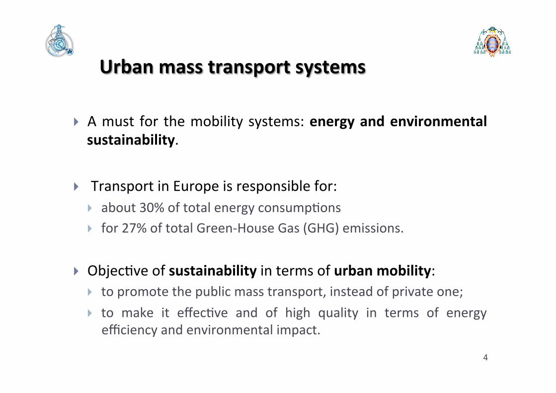
Urban mass transport systems
} A must for the mobility systems: energy and environmental sustainability.
} Transport in Europe is responsible for: } about 30% of total energy consump6ons } for 27% of total Green-‐House Gas (GHG) emissions.
} Objec6ve of sustainability in terms of urban mobility: } to promote the public mass transport, instead of private one; } to make it effec6ve and of high quality in terms of energy efficiency and environmental impact.

Urban mass transport systems: electric solu<ons
} Necessity of more energy-‐efficient and environmental sustainable transport solu<ons: electrical transport revival versus internal combus6on engine (ICE) vehicles.
} Different types of Electric Vehicles (EVs) as solu6on, with diverse quality of service, in terms of poten6al vehicles frequency (fleet size), commercial speed, level of regularity, level of security and safety.
5

Electric urban mass transport systems: common requirements for different solu<ons
} High reliability to guarantee: regularity of service and lower opera6onal costs.
} Good power-‐to-‐weight ra<o to ensure: less wear, lower energy costs, lower maintenance costs, smaller size of power systems.
} Safety to ensure protec6on of passengers from accidents.
} Comfort for passengers.
} Easiness in maintenance to guarantee service’s con6nuity in case of fault.
} Low costs in construc<on and opera<on. 6

Electric urban mass transport systems: classifica<on
} A possible classifica6on of public mobility systems based on
Electric Vehicles (EVs) can be referred to the type of
infrastructure:
} EVs on road: electric cars, electric buses, electric trolley-‐buses.
} EVs by rail: electric trams, electric light rail and electric metro-‐
transit.
} Each transport system has its own par6cular field of using, as a
func6on of the poten<al transporta<on demand and local
condi<ons. 7

Electric urban mass transport systems: classifica<on
Type of mass transport Capacity
[n. of passengers/h per way]
Bus and trolley-‐bus 2.000÷ 4.000
Tram 6.000÷ 15.000
Light rail 6.000÷ 15.000
Automa6c light rail 10.000÷25.000
Tradi<onal metro-‐transit 20.000÷45.000
8
Buses and trolley-‐buses line can have the same transport capacity, measured as number of passengers/h per way. This value can be increased choosing trams, light rails and metro-‐transit systems.
Electric urban mass transport systems: territory, environmental and economic issues
• The choice of the urban mass mobility system is strictly linked to the service to offer and to energy efficiency aspects, the planning is also very influenced by: } level of integra<on of the transport system with the other city’s infrastructures (territory “compa<bility”);
} environmental aspects (air and noise pollu<on);
} economic features.
9

} The “compa<bility” with the territory of a transport solu6on is
strongly related to the infrastructure and supplying system of the
vehicles.
} Buses: on road path in common with private transport.
} Trolley-‐buses: on road path and presence of power systems for
supplying.
} Trams, light rail and tradi<onal metro-‐transit: presence of rails and
power systems for supplying.
Electric urban mass transport systems: territory, environmental and economic issues

Electric urban mass transport systems: territory, environmental and economic issues
} Another important feature in the planning of the public mass transport is the environmental impact, which affects the quality of life of ci6zens, in terms of air pollu<on and noise emission.
} An EV is able to be a zero-‐emission vehicle in terms of local air pollu<on.
} Noise pollu<on is not only responsible for the degrada6on of the urban life quality, but it is also capable of producing physical, psychological and social damage.
Vehicle Type Noise Level [dB] ICE Bus 70-‐80
Trolley-‐bus 60-‐ 78 Tram 78-‐82
Light Rail 70-‐80 Metro-‐transit 75-‐80
Electric urban mass transport systems: territory, environmental and economic issues
} In an economic comparison, the main cost items that have to be considered are: } fixed costs related to construc6on of specific and dedicated infrastructure;
} fixed costs related to the single vehicle and to the fleet; } opera<ng costs related to the energy consump6ons; } opera<ng costs related to the line management (including the drivers salary, insurance charges, vehicles parking);
} opera<ng costs related to maintenance. 12

Electric urban mass transport systems: territory, environmental and economic issues
} An economic comparison is really hard to be simply shown and summarized.
} A good reference with a complete economical assessment for different transport systems is: } P. M. Condon and K. Dow, “A Cost Comparison of Transporta<on Modes” in Founda;onal Research Bulle;n On Sustainability By Design, No. 7, November 2009.
13

Electric urban mass transport systems: territory, environmental and economic issues
} The capital cost of a metro-‐transit system is very high and public financing is usually required: capital investments are oHen financed by taxa6on and by passenger fares.
} Most of the metro-‐transit systems are publicly owned, by local transit authori6es, and operated by a private company through a public service obliga<on.
} The opera<on cost is strongly linked to the energy consump<on.
} Nevertheless metro-‐transit seems to be a good alterna<ve to an extensive road ICE transport system with many motorways: the metro-‐transit systems allow higher capacity with minor use of the territory, less environmental impact and a lower cost for a given transport capacity.
14

Electric urban mass transport systems: metro-‐transit lines
} In the last years, there was a revival of aken6on of the industries and research centres in Europe about the metro-‐transit transport systems.
} Many studies and projects, dealing with proposals on: } upgrading ac6ons,
} new technologies,
} new management techniques.
} Energy efficiency in metro-‐transit systems became a global concern and a key topic.
15

Outline
} An introduc6on on electrical urban mass transport } Metro-‐transit systems: main features
} Power systems for metro-‐transit: } Supplying architecture, trac6on line and electrical sub-‐sta6ons
} Metro-‐trains
} Energy saving issues in metro-‐transit transport
} Design&sizing basics and some 6ps on simula6on soHware } Metro-‐transit system in Rome: an example of real applica6on
16

Metro-‐transit systems: defini<ons
} A metro-‐transit system is a public transport in urban areas with high capacity, high frequency, high speed and separated from other traffic.
} It is unchallenged in its ability to transport large amounts of people quickly over short distances with a limited use of land.
} Metro-‐transit systems typically use electric trains on rail tracks. Only few systems use other systems, like guided rubber tyres or magne<c levita<on.
17
Metro-‐transit systems: defini<ons
} Metro-‐transit and Rapid-‐transit are the most common names.
} Metro-‐transit systems are typically located in underground tunnels or elevated levels above street (viaducts): the use of tunnels inspires names such as subway, underground, while the use of viaducts inspires names such as elevated , sky-‐train or over-‐ground.
18

Metro-‐transit systems: history
} The first metro-‐transit system was the Metropolitan Railway opened in 1863, as part of London Underground. Its oldest sec6ons has been completed 150 years later (January 2013).
} In 1868 New York opened the elevated West Side and Yonkers Patent Railway.
} The technology quickly spread to other ci6es in Europe and the United States with some lines converted from steam to be electric.
} There were 19 systems by 1940 and 66 by 1984.
} On April 2014, there are 168 metro-‐transit systems in 55 countries in the world. 19

Metro-‐transit systems: some worldwide <ps
} The world's largest metro-‐transit system: } by length of routes and number of sta<ons, is New York City Subway;
} by length of lines, are Seoul Metropolitan Subway, Beijing Subway, Shanghai Metro and London Underground;
} by daily and annual ridership, are Tokyo subway system, Seoul Metropolitan Subway and Moscow Metro.
20

Metro-‐transit systems: safety and security
} Compared to other modes of transport, rapid transit has a good safety record, with few accidents.
} Rail transport is subject to severe safety regula6on, with requirements for opera6on and maintenance procedures to minimize risk.
} Head-‐on collisions are rare due to use of double tracks, and low opera6ng speeds reduce the occurrence and severity of rear-‐end collisions and derailments.
} Fire is one of the first dangers (underground environment). 21

Metro-‐transit systems: safety and security
} Rapid transit facili6es are public spaces and may suffer from security problems: peky crimes, such as pickpocke6ng and baggage theH, and more serious violent crimes.
} Rapid transit systems have been subject to terrorism with many casual6es, such as the 1995 Tokyo subway Sarin gas akack and the 2005 terrorist bombings on the London Underground.
} Security measures include video surveillance, security guards, etc. In some countries a metro-‐transit police may be established.
} The security measures are normally integrated with measures to protect revenue by checking that passengers are not travelling without paying.
22

Metro-‐transit systems: tracks and crew
} Metro-‐transit trains are electric vehicles composed by mul6ple units with lengths from three to over ten cars.
} Metro-‐trains generally run on conven<onal steel railway tracks.
} Some metro-‐lines use rubber <res for specific issues (i.e. Montreal Metro and Mexico City Metro and some lines in the Paris Métro): Rubber 6res allow steeper gradients and a soHer ride, but have higher maintenance costs and are less energy efficient. They also miss trac6on when weather condi6ons are wet or icy.
} Crew sizes have decreased throughout history, with some modern systems now running completely unstaffed trains.
23

Outline
} An introduc6on on electrical urban mass transport } Metro-‐transit systems: main features
} Power systems for metro-‐transit: } Supplying architecture, trac<on line and electrical sub-‐sta<ons
} Metro-‐trains
} Energy saving issues in metro-‐transit transport
} Design&sizing basics and some 6ps on simula6on soHware } Metro-‐transit system in Rome: an example of real applica6on
24

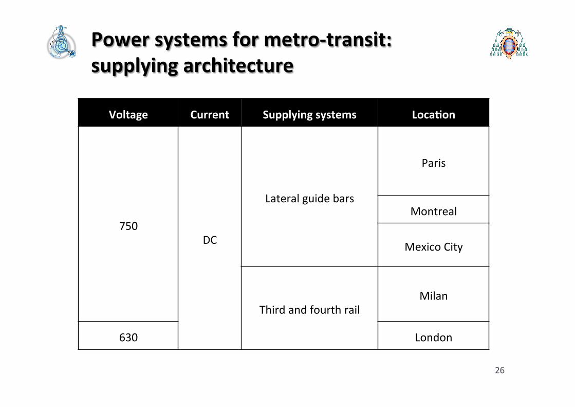
Power systems for metro-‐transit: supplying architecture
} For metro-‐trains, conven6onally running on steel railway tracks, supplying power system at 1.500, 750 or 600 V DC can be achieved with: } Overhead line (trac<on line);
} Third rail.
} In both cases the track rail is used as return circuit for the trac6on current.
} In few cases (London Underground at 630 V, or Milan Metro-‐line 1 at 750 V) a dedicated fourth rail is employed as return circuit.
} Some special system of supplying (lateral guide bars) are employed for metro-‐transit with rubber <res (Paris, Mexico, Montreal).
25
Power systems for metro-‐transit: supplying architecture
26
Voltage Current Supplying systems Loca<on
750 DC
Lateral guide bars
Paris
Montreal
Mexico City
Third and fourth rail Milan
630 London
Power systems for metro-‐transit: supplying architecture
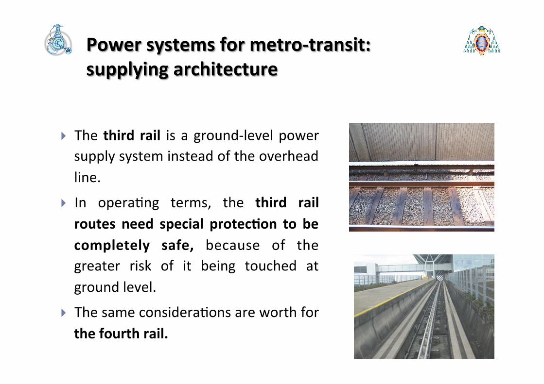
} The third rail is a ground-‐level power supply system instead of the overhead line.
} In opera6ng terms, the third rail routes need special protec<on to be completely safe, because of the greater risk of it being touched at ground level.
} The same considera6ons are worth for the fourth rail.
27

Power systems for metro-‐transit: supplying architecture
} The overhead line (trac<on line) is the most common system for supplying metro-‐trains and is used to transmit electrical energy to metro-‐trains at a distance from the main supply points, that are the trac<on electrical sub-‐sta<ons (ESSs), usually fed from a main electrical grid, operated by the local u6lity.
} Trac<on line is composed by one or more wires situated over rail tracks, raised to a DC voltage by Electrical Sub-‐Sta<ons (ESSs).
28

Power systems for metro-‐transit: supplying architecture
} To achieve good current collec6on from the overhead line, it is necessary to keep the contact wire geometry within defined limits.
} This is usually achieved by suppor6ng the contact wire by a second wire, known as the messenger wire (US & Canada) or catenary (Europe).
} The messenger wire is akached to the contact wire at regular intervals by ver<cal wires, known as droppers or drop wires.
} The messenger wire is supported regularly at structures by pulleys, links and clamps. The whole system is then subjected to a mechanical tension. 29
Power systems for metro-‐transit: supplying architecture
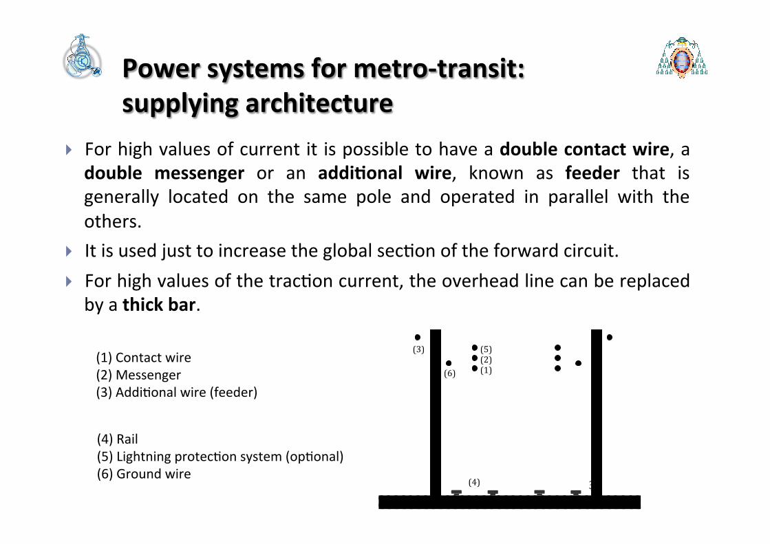
} For high values of current it is possible to have a double contact wire, a double messenger or an addi<onal wire, known as feeder that is generally located on the same pole and operated in parallel with the others.
} It is used just to increase the global sec6on of the forward circuit. } For high values of the trac6on current, the overhead line can be replaced by a thick bar.
30 30
(1) Contact wire (2) Messenger (3) Addi6onal wire (feeder)
(4) Rail (5) Lightning protec6on system (op6onal) (6) Ground wire
(1) (2) (5)
(6)
(3)
(4)

Power systems for metro-‐transit: supplying architecture
} Electric trains use as device to collect power from the overhead line a system named pantograph.
} The current collectors are electrically conduc6ve and allow current to flow through to the train and back to the feeder sta<on through the steel wheels on one or both running rails.
} The device presses against the underside of the lowest wire of the overhead line.
31

Power systems for metro-‐transit: supplying architecture
} A trac<on electrical sub-‐sta<on (ESS) is a system that converts electric power, provided by the public u6lity service, to the appropriate voltage and current type (DC) to supply the trac6on line, for the feeding of metro-‐trains.
} It has to be equipped with all the items necessary to decrease the voltage level (commonly 1.5 kV) and to rec6fy AC into DC.
} The main components are the power transformer and the solid-‐state rec<fier system.
32

alla linea di contatto
alle rotaie
+
-
+
-
SATp Ig gT Sm
R
Rp
Cp Cf
L f Sp Sa JL Sa
Sn
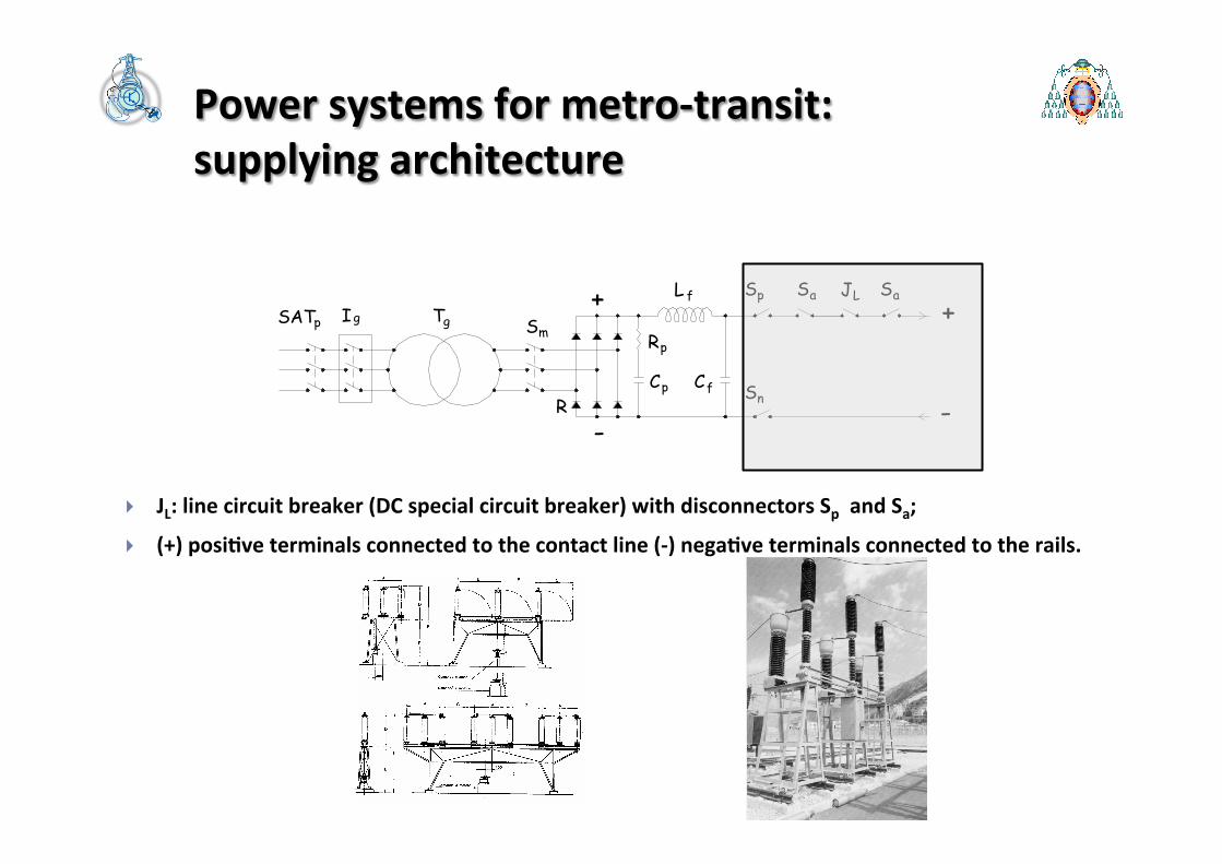
} SATP: disconnector in input on the primary HV or MV line ;
} Ig: circuit breaker for the protec6on of the ESS from overcurrent: compressed air, oil or SF6.
} Transforma6on/rec6fier group, consis6ng of transformer Tg, disconnector Sm, rec6fier R (capacitor Cp and resistance Rp for the protec6on in case of inser6ons/disconnec6on of loads);
} F: filter for harmonics due to rec6fier (inductance Lf and capacitance Cf);
} Sp and Sn: posi6ve and nega6ve disconnectors;
} JL: line circuit breaker (DC special circuit breaker) with disconnectors Sp and Sa;
} (+) posi6ve terminals connected to the contact line (-‐) nega6ve terminals connected to the rails.
Power systems for metro-‐transit: supplying architecture

alla linea di contatto
alle rotaie
+
-
+
-
SATp Ig gT Sm
R
Rp
Cp Cf
L f Sp Sa JL Sa
Sn
} SATP: disconnector in input on the primary HV or MV line ;
} Ig: circuit breaker for the protec<on of the ESS from overcurrent: compressed air, oil or SF6.
Power systems for metro-‐transit: supplying architecture
45

alla linea di contatto
alle rotaie
+
-
+
-
SATp Ig gT Sm
R
Rp
Cp Cf
L f Sp Sa JL Sa
Sn
} Transforma<on/rec<fier group, consis<ng of transformer Tg, disconnector Sm, rec<fier R (capacitor Cp and resistance Rp for the protec<on in case of inser<ons/disconnec<on of loads);
} F: filter for harmonics due to rec<fier (inductance Lf and capacitance Cf).
Power systems for metro-‐transit: supplying architecture
alla linea di contatto
alle rotaie
+
-
+
-
SATp Ig gT Sm
R
Rp
Cp Cf
L f Sp Sa JL Sa
Sn
} JL: line circuit breaker (DC special circuit breaker) with disconnectors Sp and Sa;
} (+) posi<ve terminals connected to the contact line (-‐) nega<ve terminals connected to the rails.
Power systems for metro-‐transit: supplying architecture

Power systems for metro-‐transit: supplying architecture
} For reliability reasons, more than 1 group is present in each ESS.
} Special connec<on of the p o w e r t r a n s f o r m e r secondary windings and power converters are used for reducing harmonics.
37
alla linea di contatto
alle rotaie
+
-
+
-
SATp Ig gT Sm
R
Rp
Cp Cf
L f Sp Sa JL Sa
Sn

Power systems for metro-‐transit: supplying architecture
} Upgrading ac6on on ESS: to make it reversible, for giving them the possibility to give back to the main grid the power recovered during the braking of the metro-‐trains.
} Solu6ons with two converters: an AC/DC (more powerful rec<fier) and a DC/AC (less power inverter).
} Another possibility: storage systems in ESS.
38

Power systems for metro-‐transit: supplying architecture
} Each EES is operated in parallel to the previous and the next one.
} Each branch of trac6on line is supplied by the two ESSs at its terminals: } On each the double-‐end fed sec6on low voltage drops (and so low voltage
fluctua6on on the main grid of the public u6lity) and low power losses (higher efficiency) are guaranteed.
} In addi6on some points of parallel between the two routes are made along the line.
39
Power systems for metro-‐transit: supplying architecture
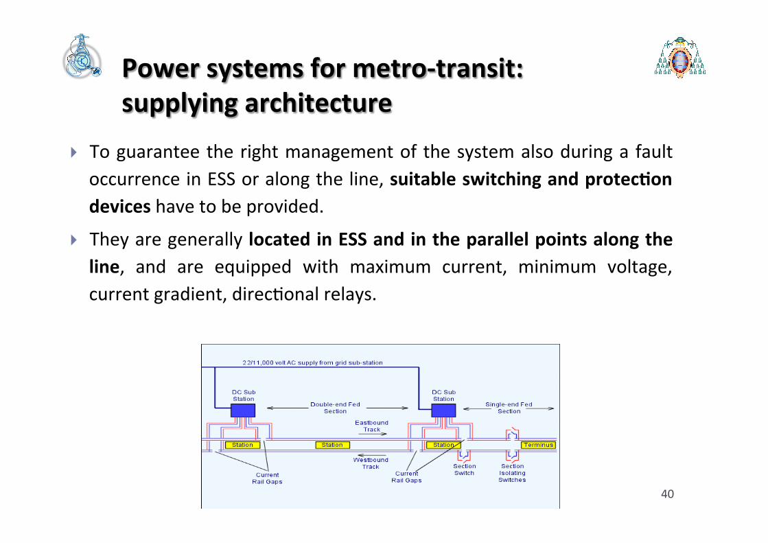
} To guarantee the right management of the system also during a fault occurrence in ESS or along the line, suitable switching and protec<on devices have to be provided.
} They are generally located in ESS and in the parallel points along the line, and are equipped with maximum current, minimum voltage, current gradient, direc6onal relays.
40

Outline
} An introduc6on on electrical urban mass transport } Metro-‐transit systems: main features
} Power systems for metro-‐transit: } Supplying architecture, trac6on line and electrical sub-‐sta6ons
} Metro-‐trains
} Energy saving issues in metro-‐transit transport
} Design&sizing basics and some 6ps on simula6on soHware } Metro-‐transit system in Rome: an example of real applica6on
41

Power systems for metro-‐transit: train features
} Trains for metro-‐lines can be equipped with:
} DC electric drives: DC motors with chopper;
} AC electric drives: AC motors with inverter.
} Electric drives are able to perform a dynamic braking, that means the conversion of kine6c energy into electricity, based on the capacity of electric motors to also act as generators.
} The use of this dynamic braking is widely spread in metro-‐lines, in couple with fric<on braking.
} The main advantages are to not generate wear and tear, dust, smell, heat or sound.
} Another poten6al advantage could be the energy saving in case of reuse of regenerated power from the electric braking.
42
Power systems for metro-‐transit: train features
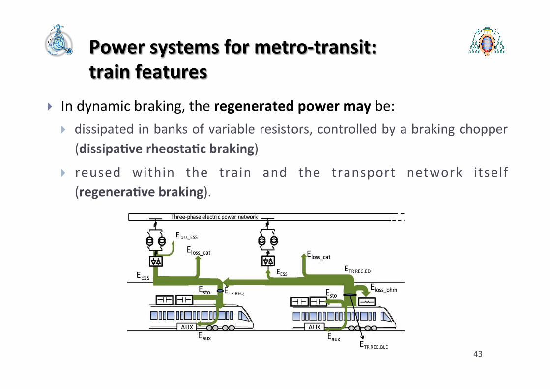
} In dynamic braking, the regenerated power may be: } dissipated in banks of variable resistors, controlled by a braking chopper (dissipa<ve rheosta<c braking)
} reused within the train and the transport network itself (regenera<ve braking).
43
EESS EESS ETR REC.ED
ETR REC.BLE
ETR REQ
Eloss_ESS

Power systems for metro-‐transit: train features
} Dissipa<ve rheosta<c braking is a non-‐efficient way to manage the energy produced by the motors during the braking phase: } The recoverable energy is wasted in heat;
} The heat produc6on is a problem in an underground environment, like most of the metro transit systems: with the aim of guaranteeing a good level of comfort, for metro-‐workers and passengers, it involves an over-‐sizing of the tunnel and sta6on fan plants with a consequent further growth in power consump6ons.
} The presence of the rheostat on board implies an addi<onal weight and costs, and is also a poten<al risk of fire.
44

Power systems for metro-‐transit: train features
} For all these reasons and with current technology, the regenera<ve braking seems to be a beker solu6on, also to reduce energy consump6on in metro-‐transit.
} Typically the recovered energy is primarily used to supply the auxiliary and comfort func<ons of the vehicle itself. Then, the energy surplus may be returned into the power supply line for use of other vehicles within the same line.
45
EESS EESS ETR REC.ED
ETR REC.BLE
ETR REQ
Eloss_ESS

Power systems for metro-‐transit: train features
} However, DC trac<on grids could not be always recep<ve: they are not always able to admit the recovered braking energy. } The recovered energy can be sent back to the supply network only when a simultaneous consump6on takes place, for instance when another train is accelera6ng in the same electric sec6on.
} To dissipate the regenerated energy that cannot be used within the system, vehicles are anyway equipped with on-‐board resistors. So the braking is called rheosta<c-‐regenera<ve.
46

Power systems for metro-‐transit: train features
} This solu6on is implemented in most of the exis<ng metro-‐transit systems all over the world.
} The amount of recovered energy depends on service frequency, train power profiles, electric grid configura<on, track profile and length of feed sec<ons and train auxiliary power.
} Studies have pointed out that up to 40% of the consumed energy could be fed back to catenary during the braking and however, measurements show only 19% is effec<vely recovered.
} The effec6ve line ability to receive the recovered energy cannot be taken for granted.
47

Power systems for metro-‐transit: train features
} A substan6al share of the braking energy to be dissipated in heat by means of on-‐board rheostats has as a first consequence the high reduc6on of the energy system efficiency, with the above said problem of heat produc6on in an underground environment.
} For these reasons, nowadays a lot of new studies and research about efficiency in metro-‐transit systems are focused on the possibility to take a full advantage of the energy regenera<on capability of the trains.
} Many proposals regard the way to manage the trains’ energy available by regenera<ve braking. 48

Outline
} An introduc6on on electrical urban mass transport } Metro-‐transit systems: main features } Power systems for metro-‐transit:
} Supplying architecture, trac6on line and electrical sub-‐sta6ons } Metro-‐trains
} Energy saving issues in metro-‐transit transport } Design&sizing basics and some 6ps on simula6on
soHware } Metro-‐transit system in Rome: an example of real applica6on
49
Energy saving issues in metro-‐transit transport
} A literature review on the topic of energy efficiency in urban metro transit systems points out the existence of different approaches: } approaches based on the op<miza<on in the design and sizing of the electric supplying system (sub-‐sta6on layout, trac6on line, reversible substa6ons, storage systems, etc…);
} approaches based on the traffic control both at the individual train level (e.g. train performance control in terms of speed and accelera6on profiles) and at fleet level (6metables, coordina6on of individual cinema6c profiles), and on-‐line centralized traffic regula6on.
50

Energy saving issues in metro-‐transit transport
} The proposals dealing with the braking energy recovering issue are focus on different possibili6es: } to maximize the use by other trains running on the same line, op6mising
scheduled 6metables so as to synchronise accelera6on and decelera6on of trains as far as possible (ATO systems) ;
} to improve the recep<vity of the line, equipping ESS with DC/ AC inverters (reversible ESS), so that the regenerated energy can be fed back to the distribu6on network, which is naturally recep6ve: special contract with the main grid u6lity;
} to install storage devices in ESS or along the track that could absorb the surplus regenerated energy or delivering it when required by trains’ accelera6on: used for lines with relevant slopes (i.e. Naples, Bilbao, etc.);
} to equip vehicles with energy storage systems that accumulate the excess regenerated energy and release it for the next accelera6on phase.
51

Energy saving issues in metro-‐transit transport
} A. Gonzalez-‐Gil, R. Palacin, P. Baky, “Sustainable urban rail systems: Strategies and technologies for op6mal management of regenera6ve braking energy”, Elsevier Journal on Energy Conversion and Management, Vol. 75, 2013, pp. 374–388.
} C.M. P. Leunga, E: W.M. Lee, “Es6ma6on of electrical power consump6on in subway sta6on design by intelligent approach”, Applied Energy. Vol. 101, January 2013, pp. 634–643.
} M. Domínguez, A. Fernández-‐Cardador, A.P. Cucala, R.R. Pecharromán, "Energy savings in metropolitan railway substa6ons through regenera6ve energy recovery and op6mal design of ATO speed profiles", IEEE Transac;ons on Automa;on Science and Engineering. July 2012, vol. 9, no. 3, pp. 496-‐504.
} W.S. Lin, J.W. Sheu, “Op6miza6on of Train Regula6on and Energy Usage of Metro Lines Using an Adap6ve-‐Op6mal-‐Control Algorithm”, IEEE Transac;ons on Automa;on Science & Engineering 2011, vol. 8, issue 4 pp. 855-‐864.
} M.C. Falvo, R. Lamedica, R. Bartoni, G. Maranzano, “Energy management in metro-‐transit systems: An Innova6ve Proposal Toward an integrated and sustainable urban mobility system including plug-‐in electric vehicles”, Electric Power Systems Research Journal. Volume 81, Issue 12, December 2011, pp. 2127-‐2138.
} M. Miyatake, H. Ko, “Op6miza6on of Train Speed Profile for Minimum Energy Consump6on”, IEEJ Transac;ons on Electrical and Electronic Engineering, 2010 vol. 5 issue 3, pp. 263-‐269.
} F. Ruelland, K. Al-‐Haddad, "Reducing Subway's Energy", Proceedings Electrical Power Conference, 2007. IEEE Canada 25-‐26 October 2007.
52

Energy saving issues in metro-‐transit transport
} To install energy storage devices on the train or at ESS can make the system beker gathering energy saving and comfort requirements.
} In favour of these solu6ons, there is also the technological evolu<on of the energy storage equipment that nowadays are able to guarantee: } higher values of specific energy,
} higher values of specific power, } longer life cycle,
} reduced environmental impact and cost and } beker dynamic performances. 53
Energy saving issues in metro-‐transit transport
} In addi6on, sta<onary storage in ESS could provide further benefits, such as: } to increase the system security, being an external source in
emergency that could supply trains, for reaching the nearest sta6on, in case of failure of the main power supply;
} to shave power peaks with consequent savings in investment costs on the power system;
} to get stable voltage profile on power line, with a consequence decreasing in losses and an improvement in terms of power quality.
} Only one drawback: feeding back the regenera6ve energy to storage devices at ESS leads to addi<onal transmission losses.
54
Energy saving issues in metro-‐transit transport
} These losses are avoided placing the storage device on-‐board vehicles, but the train mass is increased and addi6onal space is needed in the vehicle.
} The storage devices both in sta<onary and on board applica<on can be: } flywheels, which have large dimensions and are usually rejected on-‐board,
} baperies which have a limited number of load cycles,
} super-‐capacitors, preferred due to the dimensions of the storage and easy to be adapted to different voltages, power and energy ranges configuring the number of series or parallel banks. Moreover, their high-‐power density makes them useful only in few cases.
55

Energy saving issues in metro-‐transit transport
} Concluding, the recovering of trains braking energy in storages would allow a global energy saving, as beker as it is a good total consump6ons percentage, with an addi<onal improvement in case of op<miza<on of the same storage systems design.
} Obviously this result depends on the main characteris6c of the metro-‐line: power system layout, metro-‐line path, type of train, traffic scenario, etc...
} In order to have an assessment of the real energy saving guaranteed by the train braking recovering, it is necessary to perform specific analysis with dedicated soqware on the single cases.
56