electrical vehicles – practical solutions for power ... · abstract —this paper presents...
TRANSCRIPT
Abstract—This paper presents various solutions for the
power traction motors of electrical vehicles. Equivalent designs
to those commercially available on the roads are investigated.
Potential simple modifications of the winding configurations
and cooling system are studied: (a) flat wire (hairpin) winding
vs stranded round wire in induction, synchronous permanent
magnet and wound field machine topologies, (b) winding
material grades effect – copper vs aluminum, (c) cooling
systems – water jacket vs spray, fluid properties and flow rate.
Index Terms— Electrical vehicle, AC motors, permanent
magnet motors, induction motors, windings, cooling system
I. INTRODUCTION
HERE is currently wide interest in the research and
development of power traction applications driven by
electrical machines. On-going efforts are fueled by the need
for the new generations of “green” products, such as hybrid
and electric vehicles. There are mandatory emission
reduction targets for new cars in Europe. The target for
2021 (95% vehicles must achieve targets in 2020 and 100%
in 2021) is that all new cars will have maximum 95 grams
of CO2 emission per km fuel consumption of around 4.1
litres/100 km of petrol or 3.6litres /100 km of diesel fuel
[1]. Hence, in the drive train only way to achieve targets are
drive trains with electric motors [1].
Currently, for electrical vehicles there are solutions using
synchronous permanent magnet, synchronous wound field
and induction machines. We note that all power traction
solutions for electrical vehicles that are currently on the
market are of AC type. There are significant research efforts
on solutions with reluctance machines: synchronous (also an
AC machine) or switched.
Battery Electric Vehicles (BEVs)
A battery electric vehicle uses batteries to power an electric
motor to propel the vehicle. The batteries are recharged
M. Popescu, D. A Staton D. Hawkins J. Goss and Y. C. Chong are
with Motor Design Ltd., Ellesmere, U.K. (e-mails:
[email protected], [email protected],
[email protected], [email protected],
A. Boglietti is with Politecnico di Torino, Italy, (e-mail:
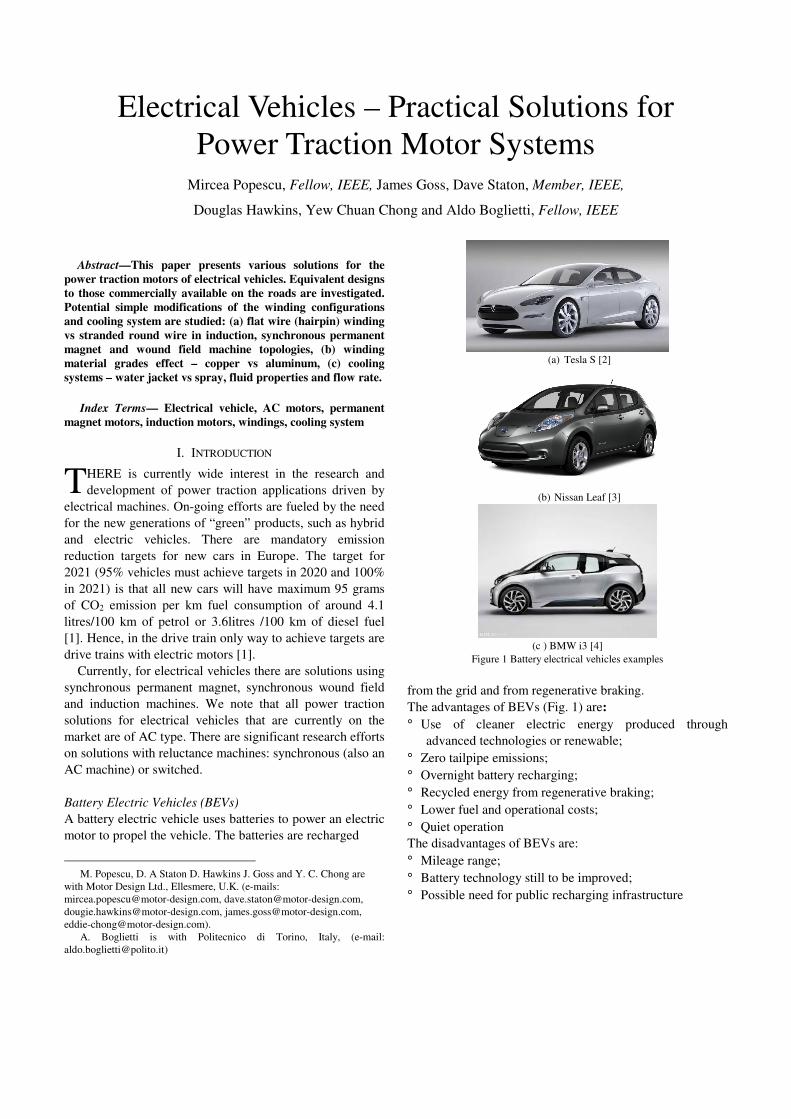
(a) Tesla S [2]
(b) Nissan Leaf [3]
(c ) BMW i3 [4]
Figure 1 Battery electrical vehicles examples
from the grid and from regenerative braking.
The advantages of BEVs (Fig. 1) are:
° Use of cleaner electric energy produced through
advanced technologies or renewable;
° Zero tailpipe emissions;
° Overnight battery recharging;
° Recycled energy from regenerative braking;
° Lower fuel and operational costs;
° Quiet operation
The disadvantages of BEVs are:
° Mileage range;
° Battery technology still to be improved;
° Possible need for public recharging infrastructure
Electrical Vehicles – Practical Solutions for
Power Traction Motor Systems Mircea Popescu, Fellow, IEEE, James Goss, Dave Staton, Member, IEEE,
Douglas Hawkins, Yew Chuan Chong and Aldo Boglietti, Fellow, IEEE
T

(a) GM Chevrolet Volt [5]
(b) Toyota Prius [6]
Figure 2 Hybrid electrical vehicles examples
Hybrid Electric Vehicles (HEVs)
Hybrid electric vehicles (Fig. 2) are powered by both
internal combustion engine and electric motor
independently or jointly, doubling the fuel efficiency
compared with a conventional vehicle.
A 'parallel' hybrid electric vehicle can use either the
electric motor or the internal combustion engine to propel
the vehicle. A 'series’ hybrid electric vehicle uses the
electric motor to provide added power to the internal
combustion engine when it needs it most.
The advantages of HEVs are:
° Optimized fuel efficiency and performance;
° Lower fuelling costs;
° Reduced fuel consumption and tailpipe emissions;
° Recovered energy from regenerative braking;
° Use of existing gas station infrastructure
The disadvantages of HEVs are:
° Higher initial cost;
° Complexity of two power trains;
° Component availability—batteries, power trains, power
electronics
Hybrid electric vehicles can be classified based on the
battery voltage and capacity:
° Micro Hybrid (low voltage 12V): Shuts down engine at
idle to save fuel;
° Mild Hybrid (low to medium voltage 12 to 120V):
Includes stop-start, regeneration braking, and
acceleration assist
° Full Hybrid (high voltage 300V+): All mild HEV
features + EV-mode
° Plug-in Hybrid (high voltage 300V+): Recharge battery
through electrical outlet
This paper is investigating and comparing various solutions
for traction motors in EVs and proposes simple
modifications that can improve the motor performance. For
relevance, initial designs are based on equivalent existing
commercial solutions [2-7]. A comprehensive comparison
between existing solutions on the market along with a
detailed reference list is given in [8]. Three categories of
traction motors are considered, depending on the power
level and vehicle type: battery electrical vehicle, plug-in
hybrid vehicles, mild hybrid vehicles. The performance
improvement or cost reduction can be achieved via various
techniques as: flat wire technology winding, oil spray
cooling, aluminium winding.
II. BATTERY ELECTRICAL VEHICLES SOLUTIONS
Most of the commercial solutions for the power traction
system in BEVs use synchronous permanent magnet motors
with embedded rare-earth magnets and distributed stranded
wire windings [3,4]. One significant exception is Tesla S
that employs an induction motor with copper rotor cage, but
also with distributed stranded wire winding. Based on the
specifications from Table I. it is possible to investigate the
peak and continuous performance of the synchronous PM vs
magnet free motor solutions, i.e. induction and synchronous
wound field motors. For all design variants, we will
consider as alternative the flat wire (hairpin) winding
similarly to the solution implemented in Chevrolet Volt [5].
Due to the manufacturing process and the existing tools
dedicated to the mass production, it not always
recommended or commercially viable to have a completely
new design, even if this may be optimized and lead to
increased efficiency and/or material costs.
This paper proposes simple modifications of existing
solutions, with minimal impact on the production line, that
would achieve increased performance. Such easy to
implement solutions are related to: (i) Flat wire (hairpin)
winding type have not been investigated in magnet-free
traction motors: induction or synchronous wound field; (ii)
Aluminum as an alternative material for the stator winding;
(iii) Efficiency cooling systems with combined water
jackets, shaft groove and oil spray elements.
The control strategy and the theory behind the models in
this paper are fully described in [9], [10], [12], [17].
TABLE I – BEV POWER TRAIN SPECIFICATIONS
Parameter Unit Value
Peak torque Nm 430
Peak power kW 270
DC bus voltage V 366
Maximum speed rpm 15000
Maximum stator current Arms 900
Maximum rotor DC current1) A 30
Axial active length mm 150
Motor outer diameter mm 280
Stator cooling system N/A Water jacket (EGW 50/50)
Rotor cooling system2) N/A Shaft grove jacket (EGW50/50)
1) Wound field motor
2) Induction and wound field motor

A. Induction Motor Solution
The main design parameters of the induction motor
solution are based on an equivalent to Tesla S 60 traction
motor design [2] (see Table II). Fig. 3 shows the radial and
axial view of the the induction motor solution. The winding
pattern consists of a concentric set of 3 coils per pole and
per phase, with a coil pitch of 10-12-14 and turns per coil of
1-2-2. There are two parallel paths in the 3-phase winding
system, so that it is possible to supply the motor, if required,
from one inverter source (3-phase system) or from two
inverter sources (6-phase system). Two winding types are
considered: (a) flat wire – hairpin – with 3 rectangular
conductors (2.45mm X 3.85mm) in hand forming one
turn/coil and (b) stranded round conductors with a wire size
AWG # 19 and 25 parallel strands in hand.
The stator lamination is modified accordingly to
accommodate the flat wire – parallel slot, and round wire –
parallel tooth (Fig. 4). Notice that the wire size and the
number of strands in hand correspond to a slot fill factor
(copper area/ slot area) equal to 0.35. This is imposed by
the automatic procedure of the coils in the stator slots. For a
better illustration, in Fig. 4b is shown the model for slots
with only one coil inserted. There are 12 slots out of 60
where two coils are inserted and phase separators are
required.
The advantage of flat wire winding associated with a
parallel slot configuration is a much higher copper slot fill
factor [15]. Potential high frequency AC losses in the flat
wire conductors can be reduced via twisting/transposition
methods [15, 16]. The twisting for flat wires consists in
different connections at the end-coil region, so that for
example a coil segment placed in a slot opening region is
connected to a coil segment placed in a slot end region. For
simplicity, this study considers straight conductors, so that
AC losses are limited just by the conductors dimensions.
There are two main choices when designing an alternative
solution with flat wire and parallel slot topology compared
to a stranded wire and parallel tooth topology:
(a) Slot area is constant – this helps with considerable
reduction of DC copper losses, but has a drawback in
the increased copper material weight that is used
(b) Copper area is constant – this helps in reducing the
saturation level as the tooth width will increase in flat
wire topology, i.e. same copper can fit in a lower slot
area due to the higher slot fill factor, but has a
disatvantage in increased AC copper losses, while the
DC losses are practically constant.
In chosing the slot dimensions, the overall total area of
the slots is kept approximately constant, so that the volume
and weight of the stator steel is similar in both designs (Fig.
4).
The rotor bars are closed and the rotor cage is built using
pure copper alloy. For consistency, it is assumed that the
rotor cage is die-cast, so that the bars and the end-ring have
the same properties, i.e. an electrical resistivity of 1.724
µΩ-cm at 20 0C.
The cooling system comprises two elements: a spiral
stator water jacket and a spiral shaft groove. Both elements
are using forced convection with water ethylene glycol
mixture (50%-50%) as heat extraction fluid and an inlet
temperature of 50 0C. As per the reference [13,14], an
induction motor for traction application is proposed to have
two cooling systems: one for the stator assembly, one for
the rotor assembly. An iterative calculation is performed to
identify suitable fluid flow rates for both cooling system and
it was considered that a fluid flow rate of 10 liters/min for
the stator water jacket and 2 liters/min for the shaft groove
respectively would be optimal. In addition, the stator end-
winding region is potted with an epoxy type material.
As comparison criteria, the peak and continuous
performance are investigated in Figs. 5 – 7. The induction
motor is controlled using maximum torque/amp control
strategy (MTPA) algorithm with a PWM modulation index
of 0.866. The choice for the modulation index corresponds
to standard linear range sine/triangle PWM signal and
represents the ratio between the peak line-line voltage at the
motor terminals and DC bus voltage, neglecting the voltage
drop in the inverter switching elements.
The peak performance is modelled considering that the
entire motor elements are at a constant temperature of
1000C and peak current 900Arms. Such assumption is
practical, as is can be verified on the test bench.
Consquently, a similar performance for both types of
winding: peak torque of 430Nm achieved up to base speed
of 6500rpm. The peak power is 292.6kW @ 6500rpm and
250kW @ 15000rpm (Figs. 5 and 6). However, the
efficiency loci shows a slight improvement in the hairpin
winding design as the reduction in DC stator copper losses
– from maximum 10500W in stranded winding design to
maximum 6000W in hairpin winding design - exceeds the
increase in high frequency AC stator copper losses – from
maximum 2000W in stranded winding design to 5000W in
hairpin winding design.
For continuous performance, a coupled model
electromagnetic-thermal was used, so that the maximum
stator winding temperature does not exceed 180 0C, which
represents industrial insulation class F, while the rotor
bearings temperature is limited at 150 0C. Such limit value
for the rotor bearings temperature is usually related to the
lubrication and maximum acceptable temperature for the
motor grease, that is polyurea based.
TABLE II – BEV INDUCTION MOTOR DETAILS
Parameter Unit Value
Stator OD mm 254
Stator ID mm 157
Airgap mm 0.5
Stator Slots / 60
Poles / 4
Rotor Bars / 74
Electric steel / M250-35A
Rotor cage / Copper

(a) Radial view (b) Axial view
Figure 3 Induction motor design for BEV
(a) flat conductors
(b) stranded conductors
Figure 4 Conductors distribution in the slot of induction motor
(a) IM 1 - hairpin winding
(b) IM 2 - stranded winding
Figure 5 Peak torque performance for an induction motor BEV
Figure 6 Continuous torque performance for an induction motor BEV
Figure 7 Continuous power performance for an induction motor BEV
The continuous performance presented in Figs. 6 and 7,
shows the benefits of the flat wire - hairpin winding over the
standard round wire winding. When hairpin winding
configuration is used and the same slot area maintained, the
maximum starting continuous torque increases by 44% from
180Nm to 260Nm, while the maximum continuous power
sees an increase of 17% from 135kW to 158kW.
For all operation speed range, the limiting thermal factor
is the stator winding maximum temperature, i.e. imposed to
be 1800C, related to the corresponding insulation class H.
Within the speed range 0 – 8000rpm, when output power
is increasing, the DC copper stator winding loss is the most
significant loss component. At higher speed, above
8000rpm, the AC copper stator winding loss increases to a
level that leads to a more rapid decrease of the torque for
hairpin winding design.
B. Synchronous Interior Permanent Magnet (IPM) Motor
Solution
The main design parameters of the synchronous
permanent motor solution, are based on a scaled-up
equivalent topology to Nissan Leaf traction motor [3, 8]
design (see Table III). Fig. 8 shows the radial and axial
view of the the synchronous IPM motor solution. The
winding pattern consists of a distributed lap set of 1 coil per
pole and per phase, with a coil pitch of 5 and turns per coil
of 6, see Fig. 9. There are four parallel paths in the 3-phase
winding system, so that it is possible to supply the motor if
required from one inverter source (3-phase system) or from
two inverter sources (6-phase system) or four inverter
sources (12-phase system).
Two winding types are considered: (a) flat wire – hairpin
– with one rectangular conductor (3.00mm X 4.00mm) in
hand forming one turn/coil and (b) stranded round
conductors with a wire size 0.71mm and 30 parallel strands
in hand. The stator lamination is modified accordingly to
accommodate the flat wire – parallel slot and round wire –
parallel tooth. In chosing the slot dimensions, the same the
copper area is maintained, so that the volume and weight of
the copper winding is similar in both designs.

The cooling system comprises one element: a spiral stator
water jacket using forced convection with water ethylene
glycol mixture (50%-50%) as heat extraction fluid and an
inlet temperature of 65 0C. It is assumed a fluid flow rate of
6.5 liters/min. As comparison criteria, the peak and
continuous performance are investigated in Figs. 10 – 12.
The IPM motor is controlled using the same parameters as
for the induction motor. The choice for the modulation
index corresponds to standard linear range sine/triangle
PWM signal and represents the ratio between the peak line-
line voltage at the motor terminals and DC bus voltage,
neglecting the voltage drop in the inverter switching
elements.
For continuous performance, a coupled model
electromagnetic-thermal was used, so that the maximum
stator winding temperature does not exceed 180 0C. The
magnets temperature is limited at 140 0C, corresponding to
an operation range recommended by the manufacturers, so
that the irreversible demagnetization of the magnet blocks is
avoided.
The peak performance at 1000C and peak current
900Arms, is similar for both types of winding: peak torque
of 430Nm is achieved up to base speed of 5800rpm. The
peak power is 279kW @ 6500rpm and 260kW @
15000rpm.
(a) Radial view (b) Axial view
Figure 8 Synchronous IPM for BEV
(a) flat conductors - hairpin (c) stranded round
conductors
Figure 9 Conductors distribution in the slot of synchronous IPM motor for
single layer pattern
TABLE III – BEV SYNCHRONOUS PM MOTOR DETAILS
Parameter Unit Value
Stator OD mm 220
Stator ID mm 146.67
Airgap mm 1.0
Slots / 48
Poles / 8
Electric steel / 30 DH
Magnet / N35UH
(a) IPM 1 – hairpin winding
(b) IPM 2 – stranded winding
Figure 10 Peak torque performance for a synchronous IPM motor BEV
Figure 11 Continuous torque performance for a synchronous IPM motor
BEV
Figure 12 Continuous power performance for a synchronous IPM motor
BEV
However, the efficiency loci shows a lower performance
in the hairpin winding design as the DC stator copper
losses are practically the same, while the increase in high
frequency AC stator copper losses – from maximum 1920W
in stranded winding design to 10000W in hairpin winding
design.
The continuous performance presented in Figs. 11 and
12, shows that if the same volume of copper is used, there
are performance benefits if using a flat wire, hairpin
winding over the standard round wire winding only at low
speed region, i.e. starting torque increases by 7.4% from
270Nm to 290Nm. However, when hairpin winding
configuration is used and keeping the same copper cross-
section area with reference to an equivalent stranded wire
design, the maximum continuous power sees a decrease of
21% from 182kW to 150kW.
The rapid decrease of torque and power at high speed
range for the hairpin winding is due to the higher AC losses
in the stator winding.
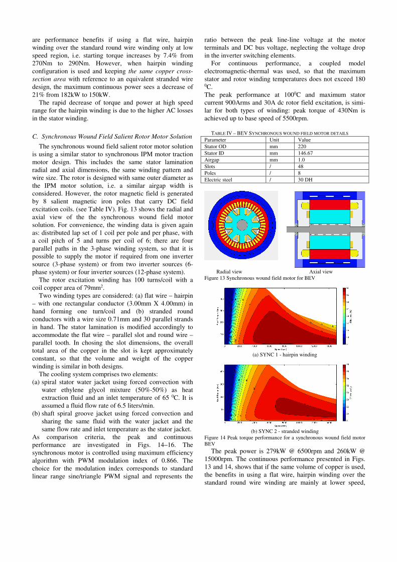
C. Synchronous Wound Field Salient Rotor Motor Solution
The synchronous wound field salient rotor motor solution
is using a similar stator to synchronous IPM motor traction
motor design. This includes the same stator lamination
radial and axial dimensions, the same winding pattern and
wire size. The rotor is designed with same outer diameter as
the IPM motor solution, i.e. a similar airgap width is
considered. However, the rotor magnetic field is generated
by 8 salient magnetic iron poles that carry DC field
excitation coils. (see Table IV). Fig. 13 shows the radial and
axial view of the the synchronous wound field motor
solution. For convenience, the winding data is given again
as: distributed lap set of 1 coil per pole and per phase, with
a coil pitch of 5 and turns per coil of 6; there are four
parallel paths in the 3-phase winding system, so that it is
possible to supply the motor if required from one inverter
source (3-phase system) or from two inverter sources (6-
phase system) or four inverter sources (12-phase system).
The rotor excitation winding has 100 turns/coil with a
coil copper area of 79mm2.
Two winding types are considered: (a) flat wire – hairpin
– with one rectangular conductor (3.00mm X 4.00mm) in
hand forming one turn/coil and (b) stranded round
conductors with a wire size 0.71mm and 30 parallel strands
in hand. The stator lamination is modified accordingly to
accommodate the flat wire – parallel slot and round wire –
parallel tooth. In chosing the slot dimensions, the overall
total area of the copper in the slot is kept approximately
constant, so that the volume and weight of the copper
winding is similar in both designs.
The cooling system comprises two elements:
(a) spiral stator water jacket using forced convection with
water ethylene glycol mixture (50%-50%) as heat
extraction fluid and an inlet temperature of 65 0C. It is
assumed a fluid flow rate of 6.5 liters/min.
(b) shaft spiral groove jacket using forced convection and
sharing the same fluid with the water jacket and the
same flow rate and inlet temperature as the stator jacket.
As comparison criteria, the peak and continuous
performance are investigated in Figs. 14–16. The
synchronous motor is controlled using maximum efficiency
algorithm with PWM modulation index of 0.866. The
choice for the modulation index corresponds to standard
linear range sine/triangle PWM signal and represents the
ratio between the peak line-line voltage at the motor
terminals and DC bus voltage, neglecting the voltage drop
in the inverter switching elements.
For continuous performance, a coupled model
electromagnetic-thermal was used, so that the maximum
stator and rotor winding temperatures does not exceed 180 0C.
The peak performance at 1000C and maximum stator
current 900Arms and 30A dc rotor field excitation, is simi-
lar for both types of winding: peak torque of 430Nm is
achieved up to base speed of 5500rpm.
TABLE IV – BEV SYNCHRONOUS WOUND FIELD MOTOR DETAILS
Parameter Unit Value
Stator OD mm 220
Stator ID mm 146.67
Airgap mm 1.0
Slots / 48
Poles / 8
Electric steel / 30 DH
Radial view Axial view
Figure 13 Synchronous wound field motor for BEV
(a) SYNC 1 - hairpin winding
(b) SYNC 2 - stranded winding
Figure 14 Peak torque performance for a synchronous wound field motor
BEV
The peak power is 279kW @ 6500rpm and 260kW @
15000rpm. The continuous performance presented in Figs.
13 and 14, shows that if the same volume of copper is used,
the benefits in using a flat wire, hairpin winding over the
standard round wire winding are mainly at lower speed,
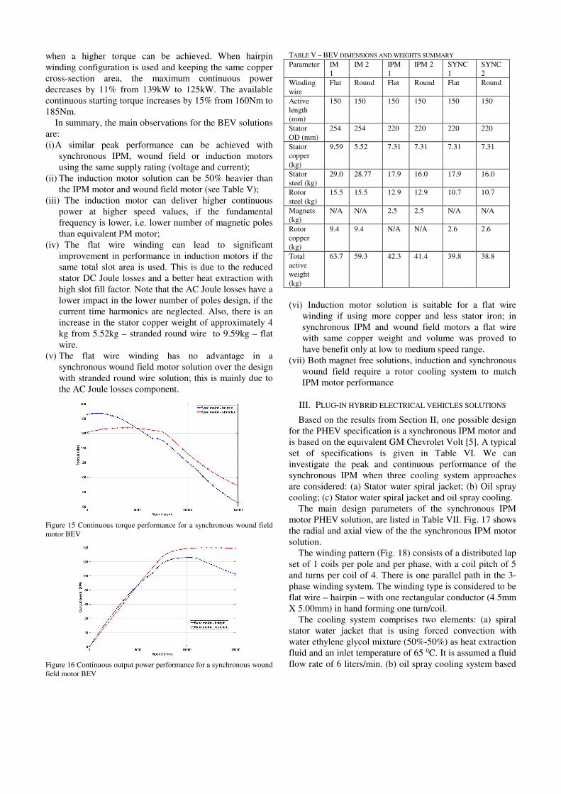
when a higher torque can be achieved. When hairpin
winding configuration is used and keeping the same copper
cross-section area, the maximum continuous power
decreases by 11% from 139kW to 125kW. The available
continuous starting torque increases by 15% from 160Nm to
185Nm.
In summary, the main observations for the BEV solutions
are:
(i) A similar peak performance can be achieved with
synchronous IPM, wound field or induction motors
using the same supply rating (voltage and current);
(ii) The induction motor solution can be 50% heavier than
the IPM motor and wound field motor (see Table V);
(iii) The induction motor can deliver higher continuous
power at higher speed values, if the fundamental
frequency is lower, i.e. lower number of magnetic poles
than equivalent PM motor;
(iv) The flat wire winding can lead to significant
improvement in performance in induction motors if the
same total slot area is used. This is due to the reduced
stator DC Joule losses and a better heat extraction with
high slot fill factor. Note that the AC Joule losses have a
lower impact in the lower number of poles design, if the
current time harmonics are neglected. Also, there is an
increase in the stator copper weight of approximately 4
kg from 5.52kg – stranded round wire to 9.59kg – flat
wire.
(v) The flat wire winding has no advantage in a
synchronous wound field motor solution over the design
with stranded round wire solution; this is mainly due to
the AC Joule losses component.
Figure 15 Continuous torque performance for a synchronous wound field
motor BEV
Figure 16 Continuous output power performance for a synchronous wound
field motor BEV
TABLE V – BEV DIMENSIONS AND WEIGHTS SUMMARY
Parameter IM
1
IM 2 IPM
1
IPM 2 SYNC
1
SYNC
2
Winding
wire
Flat Round Flat Round Flat Round
Active
length
(mm)
150 150 150 150 150 150
Stator
OD (mm)
254 254 220 220 220 220
Stator
copper
(kg)
9.59 5.52 7.31 7.31 7.31 7.31
Stator
steel (kg)
29.0 28.77 17.9 16.0 17.9 16.0
Rotor
steel (kg)
15.5 15.5 12.9 12.9 10.7 10.7
Magnets
(kg)
N/A N/A 2.5 2.5 N/A N/A
Rotor
copper
(kg)
9.4 9.4 N/A N/A 2.6 2.6
Total
active
weight
(kg)
63.7 59.3 42.3 41.4 39.8 38.8
(vi) Induction motor solution is suitable for a flat wire
winding if using more copper and less stator iron; in
synchronous IPM and wound field motors a flat wire
with same copper weight and volume was proved to
have benefit only at low to medium speed range.
(vii) Both magnet free solutions, induction and synchronous
wound field require a rotor cooling system to match
IPM motor performance
III. PLUG-IN HYBRID ELECTRICAL VEHICLES SOLUTIONS
Based on the results from Section II, one possible design
for the PHEV specification is a synchronous IPM motor and
is based on the equivalent GM Chevrolet Volt [5]. A typical
set of specifications is given in Table VI. We can
investigate the peak and continuous performance of the
synchronous IPM when three cooling system approaches
are considered: (a) Stator water spiral jacket; (b) Oil spray
cooling; (c) Stator water spiral jacket and oil spray cooling.
The main design parameters of the synchronous IPM
motor PHEV solution, are listed in Table VII. Fig. 17 shows
the radial and axial view of the the synchronous IPM motor
solution.
The winding pattern (Fig. 18) consists of a distributed lap
set of 1 coils per pole and per phase, with a coil pitch of 5
and turns per coil of 4. There is one parallel path in the 3-
phase winding system. The winding type is considered to be
flat wire – hairpin – with one rectangular conductor (4.5mm
X 5.00mm) in hand forming one turn/coil.
The cooling system comprises two elements: (a) spiral
stator water jacket that is using forced convection with
water ethylene glycol mixture (50%-50%) as heat extraction
fluid and an inlet temperature of 65 0C. It is assumed a fluid
flow rate of 6 liters/min. (b) oil spray cooling system based

on that one used by Honda Accord [6] with tubes having 12
nozzles on each side of the motor.
TABLE VI – PHEV POWER TRAIN SPECIFICATIONS
Parameter Unit Value
Peak torque Nm 398
Peak power kW 110
DC bus voltage V 366
Maximum speed rpm 8000
Maximum current Arms 420
Axial active length mm ~42.5
Cooling system N/A Water jacket (EGW)/Oil spray
TABLE VII – PHEV SYNCHRONOUS IPM MOTOR DETAILS
Parameter Unit Value
Stator OD mm 340
Stator ID mm 260
Airgap mm 1.0
Slots / 72
Poles / 12
Electric steel / M270-35A
Magnet / N35UH
(a) Radial view (b) Axial view
Figure 17 Synchronous IPM for PHEV
Figure 18 Conductors distribution in the slot of synchronous IPM motor,
single layer winding pattern
The oil drips on the end-winding of the motor with a flow
rate of 2 liters/min and an inlet temperature of 90 0C.
As comparison criteria, the peak and continuous
performance are investigated in Figs. 19–20. The IPM
motor is controlled using MTPA algorithm with PWM
modulation index of 0.95. The choice for the modulation
index corresponds to a linear range sine/triangle PWM
signal with 3rd harmonic injection and represents the ratio
between the peak line-line voltage at the motor terminals
and DC bus voltage, considering also 5% voltage drop in
the inverter switching elements.
For continuous performance, a coupled model
electromagnetic-thermal was used, so that the maximum
stator winding temperature does not exceed 180 0C, while
the magnets temperature is limited at 140 0C.
The peak performance with all the motor elements at
1000C and maximum current 420Arms, is similar for all
cooling systems: peak torque of 398Nm achieved up to base
speed of 3000rpm. The peak power is 125kW @ 3000rpm
and 105kW @ 8000rpm (Fig. 19).
The continuous performance presented in Fig. 20, shows
the great advantage of the oil spray cooling over a stator
spiral water jacket.
(a) Peak torque
(b) Peak power
Figure 19 Peak performance for a synchronous IPM motor PHEV
(a) Continuous torque comparison
(b) Continuous power comparison
Figure 20 Continuous performance for a synchronous IPM motor PHEV
The latter system has good but limited capability of heat
extraction on its own and is recommended to be used in
conjunction with the oil spray cooling systems. When both

cooling elements are active, the maximum continuous
torque increases from 185Nm to 315Nm, while the
maximum continuous power sees an increase from 68kW to
98kW.
IV. MILD HYBRID ELECTRICAL VEHICLES SOLUTIONS
One possible design for the MHEV specification is a
synchronous PM motor and is based on the equivalent
Honda Accord motor [6]. Considering the specifications
from Table VIII, we can investigate the peak and
continuous performance of the synchronous PM, when two
materials are used for the stator winding: (a) copper; (b)
pressed aluminium coils. The pressed aluminium winding is
a technology that would allow packing more material in a
pre-formed coil and hence reducing the resistance of the
coil, while increasing the thermal conductivity through a
better contact between wires [7, 17]
The main design parameters of the synchronous
permanent motor MHEV solution are listed in Table IX. TABLE VIII – MHEV POWER TRAIN SPECIFICATIONS
Parameter Unit Value
Peak torque Nm 125
Peak power kW 25
DC bus voltage V 144
Maximum speed rpm 6000
Maximum current Arms 180
Axial active length mm ~40
Cooling system N/A Water jacket (EGW)
TABLE IX – MHEV SYNCHRONOUS PM MOTOR DETAILS
Parameter Unit Value
Stator OD mm 315.5
Stator ID mm 232
Airgap mm 1.0
Slots / 24
Poles / 16
Electric steel / M270-35A
Magnet / N30UH
TABLE X – LOSS/WEIGHT COMPARISON IN MHEV SOLUTION AT: (A) 75NM
AND 2000RPM; (B) 40NM AND 6000RPM
Winding material Copper Pressed Aluminum
DC Joule loss (W) (A) 372.5 543.4
DC Joule loss (W) (B) 982 1418
AC Joule loss (W) (A) 15.58 12.67
AC Joule loss (W) (B) 325 264
Weight (kg) 3.12 1.10
(a) Radial view (b) Axial view
Figure 21 Synchronous PM for MHEV
Figure 22 Winding pattern (16 poles, double layer) for synchronous PM
motor
(a) Copper winding
(b) Aluminum winding
Figure 23 Peak torque performance for a synchronous PM motor MHEV
(a) Copper winding
Figure 24 Peak power performance for a synchronous PM motor MHEV

Fig. 21 shows the radial and axial view of the the
synchronous PM motor solution. The winding pattern (Fig.
20) consists of a concentrated set of tooth wound coils per
pole and per phase, with 52 turns per coil. There are 8
parallel paths in the 3-phase winding system. Two winding
types are considered: one with stranded round copper wire,
size 1.5mm and slot fill factor 0.40; one with pressed
aluminium wire, size 1.6mm and slot fill factor 0.46.
The cooling system comprises one elements: spiral stator
water jacket that is using forced convection with water
ethylene glycol mixture (50%-50%) as heat extraction fluid
and an inlet temperature of 65 0C. It is assumed a fluid flow
rate of 6 liters/min.
The results comparison in Figs. 23 and 24 shows that the
peak performance at 1000C overall temperature, is achieved
in a similar mode regardless of the winding material.
Figure 25 Continuous torque performance for a synchronous PM motor
MHEV
Figure 26 Continuous power performance for a synchronous PM motor
MHEV
The difference in performance appears as for the
previously analyzed cases (BEV and PHEV) at continuous
operation (Figs. 25 and 26). The thermal limits and the
efficiency of the cooling system in extracting the heat
generated by losses will determine the maximum continuous
torque and power values.
In this proposed MHEV design, as expected the copper
winding will lead to higher continuous operation limit as
compared to an aluminum winding case, i.e. 89Nm and
20kW vs 78Nm and 18kW. However, considering the cost
reduction and weight saving in winding (Table X), 3.12kg
stator copper vs 1.10kg stator aluminum, the decrease in
performance may be acceptable.
V. CONCLUSIONS
A review of various solutions for power traction motors
in electrical and hybrid vehicles is presented. Based on
equivalent designs to actual vehicles like Tesla S, Nissan
Leaf, Chevrolet Volt and Honda Accord, this paper
investigates the effect of various winding topologies in a
battery electrical vehicle, cooling system in plug-in hybrid
electric vehicle, and winding material in mild hybrid
electric vehicle.
The magnet free electrical motors – induction and
synchronous wound field – represent viable alternatives to
rare-earth magnet motors in power traction applications. A
novel solution to improve the performance of these
machines is the usage of flat wire – hairpin – windings.
Such solution was successfully implemented in brushless
permanent magnet machines, but not with induction or
synchronous wound field machines that are used in existing
power traction systems. It is shown that when moving from
a stranded wire winding design to one with flat wire –
hairpin – winding, it is preferable to keep the same slot area
and not the copper area. Only then, the reduction the DC
copper losses will overcome the increase in AC losses, such
that the motor overall performance will be improved.
Oil spray cooling systems are cheaper to implement and
could improve significantly the performance of a traction
motors if used as a secondary mode to extract the heat. As a
standalone cooling system, the oil spray cooling shows very
good potential in a how much heat can be dissipated from
the system.
A cheap alternative in reducing the weight and cost for
traction motors, can be the usage of pressed aluminum
winding coils. Even if the performance at thermal steady-
state is reduced in comparison with copper winding coils,
the cost and weight reduction may lead to preferred solution
for lower power, lower end traction applications, e.g. small
transportation vehicles or electric bikes.
VI. REFERENCES
[1] “The roadmap for transforming the EU into a competitive, low-carbon
economy by 2050” (ec.europa.eu/clima/sites/clima/)
[2] K-C Kim, “Driving Characteristic Analysis of Traction Motors for
Electric Vehicle by using FEM”, Ansys Users Conference, Seoul,
Korea, October 2014
[3] Y. Sato et al, “Development of High Response Motor and Inverter
System for the Nissan LEAF Electric Vehicle”, International World
Congress and Exhibition, Detroit, April 2011
[4] BMW documentation (bmw.com/com/en/newvehicles/i/i3/2013)
[5] S. Jurkovic, K. Rahman, B. Bae, N. Patel and P. Savagian, "Next
generation Chevy Volt electric machines; design, optimization and
control for performance and rare-earth mitigation," IEEE ECCE
Montreal, 2015, pp. 5219-5226.
[6] T. Burress et al, “Benchmarking of Competitive Technologies”, Oak
Ridge National Laboratory, May 2012.
[7] J.D. Widmer, R. Martin, and M. Kimiabeigi “Electric vehicle traction
motors without rare earth magnets” Sustainable Materials and
Technologies, No 3, 2015, pp.7-13.
[8] E.A. Grunditz, T. Thiringer, “Performance Analysis of Current BEVs
Based on a Comprehensive Review of Specifications”, IEEE Trans.
On Transportation Electrification, Vol. Vol. 2, No. 3, Sept. 2016, pp.
270-289
[9] J. Goss, R. Wrobel, P. Mellor, and D. Staton, “The Design of AC
Permanent Magnet Motors for Electric Vehicles: A Design
Methodology”, in IEEE IEMDC, Chicago, May 2013
[10] J. Goss, P. H. Mellor, R. Wrobel, D. A. Staton, and M.Popescu, “The
design of AC permanent magnet motors for electric vehicles: a
computationally efficient model of the operational envelope,” in 6th IET
International Conference on Power Electronics, Machines and Drives
(PEMD 2012), 2012, pp. B21–B21.
[11] A. Mahmoudi, W. L. Soong, G. Pellegrino, and E. Armando,
“Efficiency maps of electrical machines,” in 2015 IEEE Energy
Conversion Congress and Exposition (ECCE), 2015, pp. 2791–2799.
[12] J. Goss, M. Popescu, D. Staton, P. H. Mellor, R. Wrobel, and J. Yon,
“A Comparison between Maximum Torque/Ampere and Maximum
Efficiency Control Strategies in IPM Synchronous Machines,” in IEEE
Energy Conversion Congress and Exposition (ECCE), 2014.
[13] S.H. Swales et al, “Oil cooled motor/generator for an automotive
powertrain”, US patent application #US 8169110 B2
[14] L. Fedoseyev and E.M. Pearce Jr.“Rotor assembly with heat pipe
cooling system”, US patent application # 2014/0368064 A1
[15] Cai, W. and Fulton, D. and Congdon, C.L. “Multi-set rectangular
copper hairpin windings for electric machines”, US patent #
6,894,417, 2005
[16] Guercioni, S. “Methods for twisting rotor and stator ends”, US patent
# 8,215,000, 2012
[17] M. Popescu, D. A. Staton, A. Boglietti, A. Cavagnino, D. Hawkins
and J. Goss, "Modern Heat Extraction Systems for Power Traction
Machines—A Review," in IEEE Transactions on Industry
Applications, vol. 52, no. 3, pp. 2167-2175, May-June 2016.doi:
10.1109/TIA.2016.2518132
[18] J. Goss, M. Popescu, D. Staton, D. Hawkins, A. Boglietti, “Electrical
vehicles - practical solutions for power traction drive systems,” 2017
IEEE Workshop on Elec. Machines Design, Control and Diag.
(WEMDCD), Nottingham, U.K., pp. 80 – 88