electrically operated on/off 2 way upvc ball … · upvc is ideal for conveying potable water as it...
TRANSCRIPT

SIZE A B C D F G H W ACT.1/2 167 147 63 46 84 64 256 104 J2-203/4 167 147 63 46 108 64 256 104 J2-201 167 147 73 56 124 86 276 104 J2-20
1 1/4 167 147 73 56 142 86 276 104 J2-201 1/2 167 147 85 74 167 116 306 104 J2-20
2 167 147 85 74 198 121 306 104 J2-202 1/2 167 195 121 108 323 174 424 106 J2-55
3 167 195 121 108 269 179 424 106 J2-554 (RB) 167 195 121 108 269 179 424 106 J2-55
Specifications:
Valve body uPVC
Valve ball uPVC
Ball seats PTFE
Stem seals EPDM (Viton option)
Valve pressure range 16 b uti 2”, 10b rest*
Valve temp. limits -20C to +80C **
Supply voltage to actuator 24DC, 24, 110 or 240V AC
ELECTRICALLY OPERATED ON/OFF 2 WAY uPVC BALL VALVE
Features: > Full bore for maximum flow rate > Compact assembly > Corrosion resistant materials > Valve rated at 16 bar uti 2” at 20˚C > J2 Smart Redbox electric actuator > Local & remote visual position indication > Quick and easy to install > Economically priced
General: uPVC is ideal for conveying potable water as it is odourless and tasteless, and for conveying food products. It has excellent chemical resistance. The J2 Smart Redbox electric actuator offers multi-voltage capability, electronic torque limiter, anti-condensation heater, local and remote position confirmation and manual override. Same wiring connection for AC & DC power supplies, with external DIN plug connections, eliminating the need to remove the actuator’s cover to connect.
Applications: Water, oil, air & most non-corrosive media, subject to compatibility with wetted parts in contact with media. Pressure ratings shown are at 20˚C * Actuators sized using max differential of 6 bar wet service – if this is to be exceeded, call to check actuator sizing. ** Actuator temperature limit = +70C. For applications above this temperature, see Type 3713
Installation: Can be mounted in any orientation although valve hori-zontal with actuator vertical is preferred.. Valve ends are imperial or metric solvent weld, or BSP (Specify on order)
Dimensions:
On/Off, stays put on power failure: Type 3703
Wiring Diagram (AC or DC):
TYP
E 3
703
0203/3/105 We reserve the right to amend specifications. Uncontrolled copy not subject to automatic updates.
2 = CLOSE 3 = OPEN Items below dotted line: Customer to supply
VOLT FREE POWER
L
1 2
3
1 2
3
E E
A.C. D.C.
N - ve
+ ve
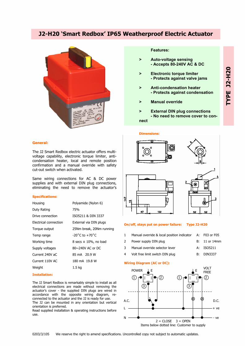
1 Manual override & local position indicator
2 Power supply DIN plug
3 Manual override selector lever
4 Volt free limit switch DIN plug
Specifications:
Housing Polyamide (Nylon 6)
Duty Rating 75%
Drive connection ISO5211 & DIN 3337
Electrical connection External via DIN plugs
Torque output 25Nm break, 20Nm running
Temp range -20˚C to +70˚C
Working time 8 secs ± 10%, no load
Supply voltages 80~240V AC or DC
Current 240V aC 85 mA 20.9 W
Current 110V AC 180 mA 19.8 W
Weight 1.5 kg
J2-H20 ‘Smart Redbox’ IP65 Weatherproof Electric Actuator
Features: > Auto-voltage sensing - Accepts 80-240V AC & DC > Electronic torque limiter - Protects against valve jams > Anti-condensation heater - Protects against condensation > Manual override > External DIN plug connections - No need to remove cover to con-nect
General: The J2 Smart Redbox electric actuator offers multi-voltage capability, electronic torque limiter, anti-condensation heater, local and remote position confirmation and a manual override with safety cut-out switch when activated. Same wiring connections for AC & DC power supplies and with external DIN plug connections, eliminating the need to remove the actuator’s
Installation: The J2 Smart Redbox is remarkably simple to install as all electrical connections are made without removing the actuator’s cover - the supplied DIN plugs are wired in accordance with the opposite wiring diagram, re-connected to the actuator and the J2 is ready for use. The J2 can be mounted in any orientation but vertical orientation is preferred. Read supplied installation & operating instructions before use.
Dimensions:
On/off, stays put on power failure: Type J2-H20 TY
PE
J2-
H20
0203/3/105 We reserve the right to amend specifications. Uncontrolled copy not subject to automatic updates.
Wiring Diagram (AC or DC):
A: F03 or F05
B: 11 or 14mm
A: ISO5211
B: DIN3337
2 = CLOSE 3 = OPEN Items below dotted line: Customer to supply
VOLT FREE POWER
L
1 2
3
1 2
3
E E
A.C. D.C.
N - ve
+ ve

GENERAL
VALVE TYPE FULL BORE 1/4 TURN BALL VALVE VALVE MODEL BV-A73 OPERATOR HAND OPERATED WITH LEVER, OR BY ACTUATOR DESIGN STANDARDS MANUFACTURERS OWN, BASED ON EN-1452-2 & EN-1452-3 FACE TO FACE DIMS MANUFACTURERS OWN TESTING STANDARDS MANUFACTURERS OWN CERTIFICATION CERTIFICATE OF CONFORMITY ONLY -MASS PRODUCED ITEM ACTUATOR MOUNTING MOUNTS WITH MOUNTING KIT SIZE RANGE 3/8” TO 4” PRESSURE RATING PN16 UTI 2”, ABOVE 2” = PN10 TEMPERATURE LIMITS WORKING PRESSURE BASED AT 20C
MATERIALS
BODY PVC-U BALL PVC-U STEM(BLOW-OUT PROOF) PVC-U SEATS PTFE SEALS EPDM OR VITON END CONNECTIONS SOLVENT SOCKET OR BSPP
FEATURES
ANTI-STATIC DEVICE NO FIRE SAFE NO PRIMARY STEM SEAL RUBBER O RING SECONDARY STEM SEAL RUBBER O RING STEM SEAL ADJUSTMENT NO IN-LINE MAINTAINABLE NO OTHER WRAS Listed for use on potable
water.
FULL BORE uPVC BALL VALVE
TYP
E B
V-A
73
0804/1 We reserve the right to amend specifications. Uncontrolled copy not subject to automatic updates.
> Full bore gives maximum flow > Actuators mount via kit > PN16 Rated UTI 2” > Imperial or metric sockets > Blow-out proof ball > Low torque > WRAS listed (Potable Water)


J2 SMART REDBOX – INSTALLATION, OPERATION & MAINTENANCE INSTRUCTIONS Read these instructions BEFORE attempting to use the actuator as damage caused by non-compliance will invalidate any warranty. If in any doubt, ask your supplier BEFORE using it.
STANDARD FEATURES:
AVS (Auto Voltage Sensing)
The J2 actuator has multi-voltage capability – it can accept a range of AC or DC power supply voltages. The J2-L series can accept from 16V to 48V AC or DC, the J2-H series from 80 to 240V AC or DC.
PES (Protected Electrical Supply)
The J2 is protected against erroneous electrical connection – if the open live and closed live terminals are inadvertently connected, whilst the actuator will not operate, no internal damage should be caused. There are no fuses. Damage will only be caused by applying a voltage in excess of 48V AC or DC to the ‘L’ series actuators.
ETL (Electronic Torque Limiter)
An electronic torque limiter is fitted to all J2 actuators. The ETL constantly monitors the motor load and immediately cuts the motor power supply if the ‘set point’ is exceeded. An internal LED, in models 20 & 55, visible through the actuator’s housing, provides constant status indication: constantly lit LED = actuator working normally, flashing LED = fault warning, the torque in the valve has exceeded the ‘set point’. This advises operators that a problem has arisen with the valve (eg: blockage). A flashing LED indicates a fault with the valve, not the actuator. The ETL automatically ‘backs off’ when activated to relax the gears, allowing the manual override to be used to assist in clearing the blockage. Once the cause of the excess torque has been cleared, the J2 will automatically reset, the LED will change to being constantly lit, and the actuator will start operating again. See instructions overleaf.
ATC (Auto Temperature Control)
An inbuilt thermostat and heater maintains the internal temperature at around 30°C to prevent the possibility of condensation forming within the housing. This system does not require a separate power supply, it is fed from the main power supply. The power supply must remain on at all times for the heater to operate.
MO (Manual Override)
All J2 actuators have a manual override facility to allow manual operation in the event of power failure. Selection of manual ( ‘MAN’ ) operation operates an internal switch which cuts the motor power – the actuator will not operate electrically whilst in manual.
VFC (Volt Free Contacts)
All J2 actuators have an additional pair of volt free mechanical micro-switch contacts which are typically used for remote position confirmation. These switches are NOT to be used for actuator motor control.
Plus: IP65 weatherproof housing, but not suitable for submersion, flooding, hose down or pressure washing. 75% duty cycle. Corrosion resistant housing with stainless cover fixings. All external electrical connection via DIN plugs, eliminating the need to remove the cover to connect. ISO5211 and DIN3337 mounting. Local visual position indicator, CE marked, ISO9002 manufactured. Serial numbered and traceable.
QUICK AND EASY TO INSTALL These user friendly actuators are designed to be fully connected WITHOUT REMOVING THE ACTUATOR COVER via externally supplied DIN plugs, simply wire the plugs and they are ready for use ! A wiring diagram label showing how to wire the plugs is affixed to the side of the actuator. Standard wiring (3 wire) for either AC or DC power supply is identical with a common, and a live switch between open and close. However, for DC power supplies, the actuators will also operate on a 2 wire system with a user supplied voltage polarity switch, used to reverse the motor, if this wiring configuration is preferred.
PEACE OF MIND
The J2 actuators are fully guaranteed against manufacturing and/ or material defects, for 12 calendar months from the date
of despatch from our works.
------------------------- Thank you for purchasing the J2 Smart RedBox. We trust that you will find them very user friendly and that if installed and operated in accordance with the following instructions, they will give you reliable and trouble free performance. E&OE 12-02 Rev 3

INSTALLATION, OPERATION & MAINTENANCE INSTRUCTIONS
STANDARD J2 ELECTRIC ACTUATORS (POWER OPEN, POWER CLOSE) INSTALLATION INSTRUCTIONS J2 actuators operate using live electricity and we strongly recommend that only qualified electricians/ electrical engineers be
employed to make electrical connections. They are quick and easy to connect without removing the cover, do not remove the cover without our authorisation or the warranty may be invalidated:
I.1 Check that the voltage being applied matches the voltage shown on the actuator’s identification label and connect the power
supply cables to the DIN plug(s) as per the wiring diagram affixed to the side of the actuator. Removing any label will invalidate the warranty. Wiring can be the same for AC or DC (3 wire), or 2 wire DC with a customer supplied voltage polarity switch, which is needed to reverse the motor. If in doubt, ASK BEFORE CONNECTING. Ensure that the rubber seal is refitted between the Din plug and base to maintain the IP65 seal. Do not over-tighten the plug securing screw.
I.2 Do not connect a power supply voltage in excess of 48V to the low voltage (J2-L) series as irreparable damage will be caused and any warranty invalidated.
I.3 If the volt free plug is not being used, leave the plug fitted to the actuator to maintain its IP65 weatherproof rating. Take care not to knock the DIN plugs as this may pull the DIN plug base away from the actuator which in turn will break the body seal and permit water to access the housing. Damage of this nature invalidates any warranty.
I.4 All J2 actuators are supplied with volt free position confirmation switches (limit switches) that require a separate power supply to operate (rated 240V 5A) The suggested wiring as per the wiring diagram affixed to the side of the actuator shows the same voltage for the actuator being used as the power source for these switches – this is a suggestion only and any standard control voltage can be used (eg: 24VDC).
I.5 Whilst the J2 actuators can be fitted in any orientation we recommend installing the actuator vertically wherever possible. Be aware of applications where elevated temperatures could be present and allow for the possibility of heat rising – in these cases use an extended mounting kit to help dissipate the heat, and mount the actuator horizontally.
OPERATING INSTRUCTIONS These actuators work with the use of cams which operate limit switches which control the starting, stopping, and direction of rotation of an electric motor. These cams are factory set at 0 and 90 degrees and whilst they are adjustable, should not normally require any user adjustment.
O.1 Supply a continuous (not pulse) live signal (either open live, or close live) to operate the actuator. The actuator will rotate until
the cams operate the micro switch and cut the power to the motor. The actuator will stay in this position until a further continuous live signal is received to send it to its opposite position. The in-built heater uses this mains supply and therefore the power supply voltage should remain on at all times.
O.2 The rest positions are as per the moulded open and closed logos, indicated by a local visual position indicator. NEVER move the set position of this indicator or a false position will be indicated.
O.3 In the case of mains power failure, the actuator will stay in the position it saw at the moment of power interruption. Should the actuator need to be operated under these circumstances, use the manual override facility, but remember to reset the selector lever in the AUTO position when the movement is completed as selection of ‘MAN’ cuts the power to the motor.
O.4 All J2 actuators have an electronic torque limiter which cuts the motor power if the applied torque exceeds the actuators rated output. Visual status indication is provided in models 20 & 55 by an internal LED which remains continuously lit when working normally, but flashes when the limiter is activated. A flashing LED indicates a problem with the valve, not the actuator. (Cut the power, clear the cause of the excess torque eg: valve jammed, turn power back on and the limiter will reset allowing normal operation)
MANUAL OVERRIDE
1.1 All J2 actuators have a manual override facility, operated by a selector lever which disengages the motor drive when moved from AUTO to MAN (Manual). The gearbox contains planetary gears and it may be necessary to ‘wiggle’ the selector lever whilst gently moving the manual override handle to ensure the gears disengage and re-engage. When resetting into AUTO – a positive ‘click’ will be felt when the gears have correctly re-engaged. A safety cut out switch activated by the manual override selector lever, which cuts the power to the motor when in the MAN position. When MAN is selected, the actuator will not operate electrically.
1.2 NEVER remove the selector lever retaining screw as this will allow the operating mechanism to become free and will cause irreparable damage to the actuator’s gearbox. Removing this screw will invalidate any warranty.
1.3 When in AUTO mode, the manual override operating handle rotates on models 20 & 55 – restricting this rotation may activate the ETL. In these circumstances, switch off the power, leave a few seconds and turn back on – the ETL will automatically reset
1.4 When in MAN mode, avoid rotating the actuator beyond the open and closed logos moulded on the top of the actuator. There are no mechanical stops fitted to the actuator (to allow rotations of 120 and 180 degrees) and it is therefore possible to over rotate the actuator. Over rotation will position the internal cams beyond their micro switches which will result in abnormal first following operation of the actuator when reset into AUTO mode (the actuator may rotate up to 450 degrees until the cam resets in the correct position).
A yellow indicator identifies the open and closed logos:
MAINTENANCE M.1 These actuators are designed to be maintenance free, the gearbox is factory lubricated for life and there are no internal parts
that require maintenance. E&OE 12-02 Rev 3
OPEN CLOSED
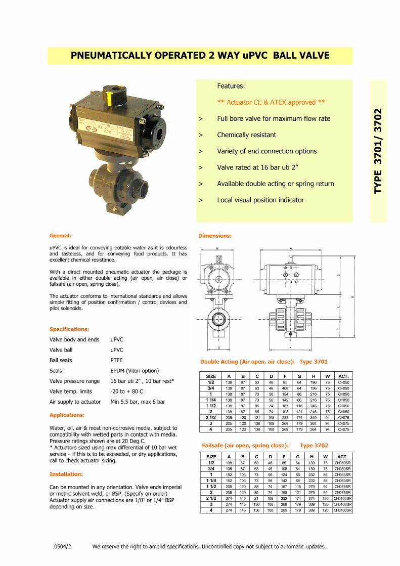
PNEUMATICALLY OPERATED 2 WAY uPVC BALL VALVE
Features: ** Actuator CE & ATEX approved ** > Full bore valve for maximum flow rate > Chemically resistant > Variety of end connection options > Valve rated at 16 bar uti 2” > Available double acting or spring return > Local visual position indicator
General: uPVC is ideal for conveying potable water as it is odourless and tasteless, and for conveying food products. It has excellent chemical resistance. With a direct mounted pneumatic actuator the package is available in either double acting (air open, air close) or failsafe (air open, spring close). The actuator conforms to international standards and allows simple fitting of position confirmation / control devices and pilot solenoids.
Specifications:
Valve body and ends uPVC
Valve ball uPVC
Ball seats PTFE
Seals EPDM (Viton option)
Valve pressure range 16 bar uti 2” , 10 bar rest*
Valve temp. limits -20 to + 80 C
Air supply to actuator Min 5.5 bar, max 8 bar
Applications: Water, oil, air & most non-corrosive media, subject to compatibility with wetted parts in contact with media. Pressure ratings shown are at 20 Deg C. * Actuators sized using max differential of 10 bar wet service – if this is to be exceeded, or dry applications, call to check actuator sizing.
Installation: Can be mounted in any orientation. Valve ends imperial or metric solvent weld, or BSP. (Specify on order) Actuator supply air connections are 1/8” or 1/4” BSP depending on size.
Dimensions:
Double Acting (Air open, air close): Type 3701
Failsafe (air open, spring close): Type 3702
TYP
E 3
701/
37
02
0504/2 We reserve the right to amend specifications. Uncontrolled copy not subject to automatic updates.
SIZE A B C D F G H W ACT.1/2 138 87 63 46 85 64 139 75 CH050SR3/4 138 87 63 46 108 64 139 75 CH050SR1 152 103 73 56 124 86 232 86 CH063SR
1 1/4 152 103 73 56 142 86 232 86 CH063SR1 1/2 205 120 85 74 167 116 279 94 CH075SR
2 205 120 85 74 198 121 279 94 CH075SR2 1/2 274 145 21 108 232 174 374 120 CH0100SR
3 274 145 136 108 269 179 389 120 CH0100SR4 274 145 136 108 269 179 389 120 CH0100SR
SIZE A B C D F G H W ACT.1/2 138 87 63 46 85 64 196 75 CH0503/4 138 87 63 46 408 64 196 75 CH0501 138 87 73 56 124 86 216 75 CH050
1 1/4 138 87 73 56 142 86 216 75 CH0501 1/2 138 87 85 74 167 116 246 75 CH050
2 138 87 85 74 198 121 246 75 CH0502 1/2 205 120 121 108 232 174 349 94 CH075
3 205 120 136 108 269 179 364 94 CH0754 205 120 136 108 269 179 364 94 CH075

GENERAL
VALVE TYPE FULL BORE 1/4 TURN BALL VALVE VALVE MODEL BV-A73 OPERATOR HAND OPERATED WITH LEVER, OR BY ACTUATOR DESIGN STANDARDS MANUFACTURERS OWN, BASED ON EN-1452-2 & EN-1452-3 FACE TO FACE DIMS MANUFACTURERS OWN TESTING STANDARDS MANUFACTURERS OWN CERTIFICATION CERTIFICATE OF CONFORMITY ONLY -MASS PRODUCED ITEM ACTUATOR MOUNTING MOUNTS WITH MOUNTING KIT SIZE RANGE 3/8” TO 4” PRESSURE RATING PN16 UTI 2”, ABOVE 2” = PN10 TEMPERATURE LIMITS WORKING PRESSURE BASED AT 20C
MATERIALS
BODY PVC-U BALL PVC-U STEM(BLOW-OUT PROOF) PVC-U SEATS PTFE SEALS EPDM OR VITON END CONNECTIONS SOLVENT SOCKET OR BSPP
FEATURES
ANTI-STATIC DEVICE NO FIRE SAFE NO PRIMARY STEM SEAL RUBBER O RING SECONDARY STEM SEAL RUBBER O RING STEM SEAL ADJUSTMENT NO IN-LINE MAINTAINABLE NO OTHER WRAS Listed for use on potable
water.
FULL BORE uPVC BALL VALVE
TYP
E B
V-A
73
0804/1 We reserve the right to amend specifications. Uncontrolled copy not subject to automatic updates.
> Full bore gives maximum flow > Actuators mount via kit > PN16 Rated UTI 2” > Imperial or metric sockets > Blow-out proof ball > Low torque > WRAS listed (Potable Water)

CH-air CE/ ATEX APPROVED PNEUMATIC ACTUATORS
> Full bore valve for maximum flow rate > Chemically resistant > Variety of end connection options > Valve rated at 16 bar uti 2” > Available double acting or spring return > Local visual position indicator > Robust & reliable > Economically priced
Body: Aluminium alloy, extruded acc. to ASTM 6063, anodised acc. To UNI 4522
Ends: Die-cast in aluminium alloy acc. To ASTM B179, epoxy-polyester coated
Pistons: Die-cast in aluminium alloy acc. To ASTM B179
Pinion: Nickel-plated steel
Slideways: Acetal resin (LAT LUB 731320T)
Fasteners: AISI 304 Stainless steel
Springs: Epoxy coated steel, pre-compressed (de-energise before end cap bolts are removed)
Seals: NBR Nitrile rubber (Viton or EPDM on request)
Lubricant: MoS2
Materials of construction:
Installation : Can be mounted in any orientation. Actuator supply air connections are 1/8” or 1/4” BSP depending on size. Use filtered compressed air min 1 bar, max 8 bar. Maintenance: Maintenance free during normal use . Full spare seal kits available.
Features: ** CE & ATEX approved ** > High quality components & assembly > Durable in service - fit & forget > Fully compliant with all actuator standards > Available double acting or spring return > Local visual position indicator > Fully balanced air and spring strokes > Body coating options C
H-a
ir P
neu
mat
ic A
ctu
ator
s
General: CE Marked in acc with EC Machinery Directive 98/37/CEE ATEX approved EX II 2 GD Tmax=95˚C (ATEX 94/9/CEE Cert: EX9 04 04 52727 001) Actuator bore machined to Ra 0.4~0.6 to minimise friction and maximise the life of the actuator. Sliding parts made of low friction coefficient avoid metal to metal contact extending working life. Running test and 100% seal test using electronic equipment on every actuator. Valve mounting drilling to ISO5211—dual drilled on most sizes for maximum flexibility. Output drive to ISO5211/DIN3337 in double square form (star) for maximum mounting flexibility. Air connections according to NAMUR standard. Position control and monitoring connections according to NAMUR standard. Factory lubrication is guaranteed for 1,000,000 manoeuvres. Visual position indicator Adjustable end of travel stops in both directions. Working temperature limits: -20˚C to +80˚C
Dimensions: See separate sheet Torques: See separate sheet
0405/1 We reserve the right to amend specifications. Uncontrolled copy not subject to automatic updates

The manufacturer declares that the entire range of CH-air pneumatic rack & pinion actuators in aluminium alloy are engineered and manufactured in accordance with the CE directive ATEX—94/9/CEE
DECLARATION OF CONFORMITY: CH-air PNEUMATIC ACTUATORS
ATEX - 94/9/CEE
In accordance with: EN1127-1 & EN13463-1 Machinery Directive 98/37/CEE
Other standards: ISO5211, DIN3337, VDI/VDE3845 UNI EN ISO 9001:2000
Certificate No: EX9 04 04 52727 001
CE Directive PED—97/23/CEE states: Actuators are not considered to be ‘recipients under pressure’ or ‘safety accessories’. To respect the directive, and also as a general safety norm, switching on the machine where the de-vice will be assembled, is forbidden before the machine is declared to conform to the directive.
SAFETY INSTRUCTIONS In compliance with ATEX 94/9/CEE Directive -Rev 01/01/2004
1 DESCRIPTION & IDENTIFICATION: The application filed of the present documentation is represented by Rack & Pinion actuators (APR) in aluminium alloy: SERIES AP (90˚ rotation) SERIES APY (120˚ rotation) SERIES APX (180˚ rotation) The identification nameplate shows: MODEL: CH xx (xx = size) SERIAL NO: xx yy zzzzz (xx = year of manufactur, yy = month of manufacture, zzzzz = progressive serial number) Rack and pinion (APR) actuators in aluminium alloy are engineered and manufactured according to ATEX 94/9/CEE directive and EN1127-1 and EN13463-1 standards as components to be used in explosive atmospheres. They can be used in the following dangerous zones: 1 and 2 (gas) & 21 and 22 (dust) 2 TECHNICAL FEATURES: The identification nameplate shows: Ambient temperature –Low temperature -40 to +80 C Ambient temperature –Standard -20 to +80 C Ambient temperature –High temperature -20 to +150 C Maximum supply pressure for continuous operation: 8 BAR WARNING: Maximum supply pressure: 10 BAR Motion fluid: dry or lubricated compressed air, inert gases, water, or non-dangerous fluids. 3 MARKING: Rack and pinion (APR) actuators in aluminium alloy are classified according to the following type of protection: Group of Devices II (surface) - Category 2 (surface excluding mines) G (gas) and D (dust) Low temperature: -40 to +80 II 2GD Tmax = 95C Standard: -20 to +80 II 2GD Tmax = 95C High temperature: -20 to +150C II 2GD Tmax = 165C 4 WARNINGS AND NOTES FOR USE: • Before installation, read our ‘Instruction Manual for Use and Maintenance’ carefully. • Follow the expected use. • Follow the indications of maximum temperature/ environment stated on the nameplate. • Do not supply any flammable or explosive media to drive the actuator (oxygen, acetylene etc). • Avoid the penetration of explosive atmospheres inside the actuator. • Do not allow the external parts of the actuator to be struck by metallic objects as this may create a spark. • Do not force the actuator manually over its maximum output torque. • Avoid the accumulation of combustible dusts on the external surfaces of the actuator. • Avoid the accumulation of electrostatic charges on insulating surfaces of the actuator by grounding (eg: fixing bolts to valve). • All components and accessories installed on the actuator for position monitoring and control purposes must be suitable for use in
accordance with the danger classification of the area in which they are being installed and used. • Maintenance of the actuator must be in accordance with the applicable standards (eg: EN50281 or E 60079 etc) and with the dan-
ger classification of the area in which the maintenance is to be performed. • Do not carry out maintenance in areas with potentially explosive atmospheres. • Verify the functionality of the springs every 100,000 (one hundred thousand) cycles and replace only with complete CH-air spring
cartridges when necessary—do no try to disassemble the spring cartridges. • Verify all rubber sealing elements (‘O’ rings and gaskets) and all plastic anti-friction pads every 300,000 (three hundred thousand)
cycles, replace only with CH-air spare seal kits when necessary. • It is the user’s responsibility to ensure that the CH-air actuators are used only in complete compliance with the ‘Instruction Man-
ual for Use and Maintenance’ and the above instructions as, non compliant use may cause danger to persons and property, and any non compliant use invalidates any warranty from the manufacturer or any legal obligation from, or claim on the manufacturer.

CH- air® RACK & PINION 1/4 TURN PNEUMATIC ACTUATORS FEATURES & BENEFITS FEATURE BENEFITS THE CH-air RANGE OF PNEUMATIC ACTUATORS OFFER SIMPLE INSTALLATION AND USE & ARE DESIGNED TO BE DURABLE IN SERVICE. FIT & FORGET. MANUFACTURED IN ACC. WITH ISO9001 1. INDEPENDANTLY ASSESSED PROCEDURES TO PRODUCE A QUALITY PRODUCT.
CE MARKED 1. CONFORMS TO REQUIREMENTS OF EC MACHINERY DIRECTIVE
ATEX APPROVED 1. CONFORMS TO REQUIREMENTS FOR ATEX- HAZARDOUS AREA APPROVAL
DURABLE IN SERVICE - GUARANTEED FOR 1 MILLION CYCLES 1. HIGHLY ACCURATE MACHINING OF INTERNALS PRODUCES AN ASSEMBLED ACTUATOR WITH LOW FRICTION CHARACTERISTICS IMPROVING RELAIBILITY & DURABILITY IN SERVICE 2. FACTORY LUBRICATED FOR LIFE
FULLY SUPPORTED PINION WITH TEFLON BEARINGS 1. MAINTAINS CONCENTRICITY OF PINION 2. REDUCES RISK OF METAL TO METAL CONTACT WITH BODY
CONFORMS TO ISO5211/ DIN3337 1. SIMPLE MOUNTING TO COMPLIANT VALVES AND MOUNTING KITS 2. STAR OUTPUT DRIVES ALLOWS MOUNTING TO IN-LINE VALVE STEMS OR STEMS AT 45 DEGREES. MORE FLEXIBLE THAN SINGLE SQUARE DRIVE.
CONFORMS TO NAMUR/ VDI-VDE3845 1. SIMPLE FITTING OF POSITION CONTROL & MONITORING DEVICES: EG; PILOT OLENOIDS, SWITCH BOXES, POSITIONERS
RACK & PINION DESIGN 1. INDUSTRY STANDARD, PROVEN IN SERVICE 2. HIGHER MID-POSITION TORQUE OUTPUT COMPARED TO SCOTCH YOKE,
HARD ANODISED ALUMINIUM BODY, EPOXY COATED END CAPS 1. EXCELLENT RESISTANCE FROM CORROSION IN NORMAL ATMOSPHERES
BALANCED SPRING RETURN VERSION 1. AIR STROKE OUTPUT = SPRNG STROKE OUTPUT 2. SAME LOAD ON VALVE STEM IN BOTH DIRECTIONS 3. EASIER TO SIZE – NO JUGGLING WITH AIR STROKE Vs SPRING STROKE
ADJUSTABLE OPEN AND CLOSED POSITION 1. OPEN POSITION ADJUSTABLE EXTRNALLY VIA END CAPS 2. CLOSED ADJUSTMENT INTERNAL. PROTECTS AGAINST MAL-ADJUSTMENT
LOCAL VISUAL POSITION INDICATOR 1. AT A GLANCE LOCAL VISUAL POSITION INDICATION WITH BRIGHT YELLOW INDICATORS. IN-LINE MAINTAINABLE WITHOUT SPECIALIST TOOLS 1. NO NEED TO RETURN TO SUPPLIER FOR OVERHAUL
2. SPRING RETURN VERSIONS HAVE PRE-COMPRESSED SPRING CARTRIDGES THAT FULLY RELAX BEFORE THE END CAP SECURING SCREWS ARE REMOVED 3. SOFT SEAL KITS AVAILABLE FOR ALL SIZES
OPTIONAL BODY COATINGS 1. ENP (ELECTROLESS NICKEL PLATING) GIVES STAINLESS LIKE APPEARANCE, IDEAL FOR FOOD AND PHARMACEUTICAL APPLICATIONS 2 TEFLON COATING SUPERCEDES FORMER EPOXY COATING
SERIAL NUMBERED NAMEPLATE 1. SHOWS MODEL NUMBER, DA OR SR VERSION & SERIAL NUMBER 2. SERIAL NUMBER DATE CODED
SPECIAL CONFIGURATIONS 1. DIRECTION OF ROTATION CAN BE CHANGED BY REVERSING PISTONS 2. 120 AND 180 DEGREE VERSIONS AVAILABLE IN SOME MODELS 3. ELEVATED TEMPERATURE VERSION (SEAL & GREASE CHANGE)

J3 Status light functions:
The LED flashes on/ off
When the actuator senses an impending valve jam, the elec-tronic torque limiter is acti-vated and on activation,
repeatedly flashes the LED on and off.
Constantly lit LED
If the actuator is operating correctly with no faults, the LED shows a constantly lit
light.
The LED flashes with 2 blinks
If the actuator has been left in ‘manual’ mode, the actuator’s motor runs but doesn’t drive the output shaft. After a pre-set time, the actuator knows that as the torque limiter has not activated and that the motor is running, it must be in manual.
Jan 2008
Doc: J3-Cat/01
The effect of condensation is eliminated by an internal ther-mostatic anti-condensation heater that does not require a separate independent power supply.
Standard function for the
J3 is power open, power close, stays put on power
failure.
New to the J3 are plug and play accessories –the function can be changed to either failsafe or modulating by fitting the new plug and play conversion kits. The modulating kit has the new digital positioner that offers auto-calibrating and self reset-ting functionality.
These conversion kits are avail-able as optional extras.
The J3 is a very smart red box!
Feature rich J+J multi-voltage actuator with LED status light and plug & play accessories.
New in 2008, the J3 range of electric actuators takes its highly successful predecessor, the J2 range, to the next level.
With an all new, rugged weath-erproof and anti-corrosive Polyamide housing, the J3 offers more user-friendly fea-tures than the J2, and intro-duces a highly visible LED status light. This visual indicator shows whether the actuator is operat-ing correctly, or has tripped out either by its electronic torque limiter, or has been left in ‘manual’ mode.
Site operators are no longer left with the ‘valve or actuator?’ question when an actuator doesn’t respond to a signal.
The J3 is quick and easy to install, with IS0:5211 multi- flange mounting and a double square drive, allowing fast
mounting to ISO:5211 valves. There is no need to remove the cover to connect the J3 elec-trically, saving installation time.
Using the external DIN plugs and external wiring diagrams supplied with the actuator, installations can be pre-wired.
Protection against valve jams is provided by an electronic torque limiter, which auto-relaxes the gearbox when acti-vated, allowing the manual override to be selected to assist in clearing the jam.
Quick guide to the J3’s standard features :
Multi-voltage with auto-voltage sensing. ‘L’ 12 ~ 24V AC or DC . ‘H’ 110 ~ 240V AC or DC
LED Status light to indicate operational status of actuator
Electronic over-torque protec-tion against valve jams
Thermostatic anti-condensation heater
Manual override for emergency hand operation
2 Volt free end of travel confir-mation switches
IP65 weatherproof anti-corrosive and UV protected Polyamide housing
Local visual position indicator
ISO5211 multi-flange mounting with double square drive
All external electrical connec-tions via supplied DIN plugs
CE marked
IS0 9000 manufacturer
Failsafe and digital positioner plug & play kits available.
Model J3

Specifications:
Optional extras:
J3 Full model listing
Model 20 Model 35 Model 55
J3 -L20 J3 -H20 J3 -L35 J3 -H35 J3 -L55 J3 -H55 J3 -L85 J3 -H85
Voltage AC (1ph) or DC 12 -
24
85 -
240
12 -
24
85 -
240
12 -
24
85 -
240
12 -
24
85 -
240
Working time - secs
0-90° (no load) ±10%
15
15
11 11 11 11 13 13
Max run toque Nm 20 20 35 35 55 55 85 85
Max break torque Nm 25 25 38 38 60 60 93.5 93.5
Duty rating % 75 75 75 75 75 75 75 75
IP rating IEC 60529 IP65 IP65 IP65 IP65 IP65 IP65 IP65 IP65
Working angle Std° 90 90 90 90 90 90 90 90
Temp range °C -20 to
+60
-20 to
+60
-20 to
+60
-20 to
+60
-20 to
+60
-20 to
+60
-20 to
+60
-20 to
+60
Motor switch 2 x V3 2 x V3 2 x V3 2 x V3 2 x V3 2 x V3 2 x V3 2 x V3
Volt free end of travel
confirmation
2 x V3 2 x V3 2 x V3 2 x V3 2 x V3 2 x V3 2 x V3 2 x V3
Anti-condensation Heater (W) 4 4 4 4 4 4 4 4
Current (full load) 12VDC
24VDC
24V/1ph
110V/1ph
240V/1ph
1.03A
0.48A
0.98A
0.19A
0.12A
1.13A
0.48A
0.98A
0.24A
0.13A
1.96A
0.77A
1.75A
0.31A
0.19A
2.88A
1.03A
1.96A
0.38A
0.21A
Weight Kg 1.5 1.5 1.8 1.8 2.0 2.0 2.0 2.0
ISO:5211 F03,04
& F05
F03,04
& F05
F03,04
& F05
F03,04
& F05
F05 &
F07
F05 &
F07
F05 &
F07
F05 &
F07
DIN:3337 Double Square drive 14 14 14 14 17 17 17 17
Model 85
Failsafe (BSR) Standard on/off version can be converted to failsafe using a plug & play conversion kit. Failsafe achieved with the use of
industrial re-chargeable batteries which are supplied with the BSR conversion kit.
Modulating (DPS) Standard on/off actuator can be converted to modulating using a plug and play conversion kit. The modulating function
is achieved with a self calibrating digital positioner (either 0-10V or 4-20mA I/O) supplied with the DPS conversion kit.
Failsafe & Modulating (BSR+DPS) Install both kits !
BSR kit DPS kit

Dimensions:
Type J3
J3 -20
J3 –35
J3 –55
110 mm
3.32”
110 mm
3.32”
110 mm
3.32”
177 mm
6.97”
177 mm
6.97”
177 mm
6.97”
149 mm
5.87”
171 mm
6.73”
196 mm
7.72”
196 mm
7.72”
J3
J3 – 85
128 mm
5.04”
177 mm
6.97”
Type J3 J3
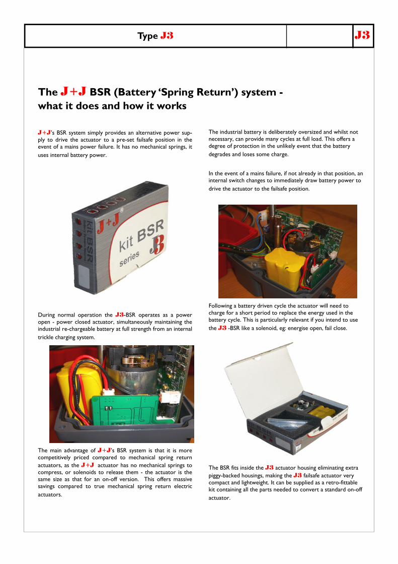
J+J’s BSR system simply provides an alternative power sup-ply to drive the actuator to a pre-set failsafe position in the event of a mains power failure. It has no mechanical springs, it uses internal battery power.
During normal operation the J3-BSR operates as a power open - power closed actuator, simultaneously maintaining the industrial re-chargeable battery at full strength from an internal trickle charging system.
The main advantage of J+J’s BSR system is that it is more competitively priced compared to mechanical spring return actuators, as the J+J actuator has no mechanical springs to compress, or solenoids to release them - the actuator is the same size as that for an on-off version. This offers massive savings compared to true mechanical spring return electric actuators.
The J+J BSR (Battery ‘Spring Return’) system - what it does and how it works
The industrial battery is deliberately oversized and whilst not necessary, can provide many cycles at full load. This offers a degree of protection in the unlikely event that the battery degrades and loses some charge.
In the event of a mains failure, if not already in that position, an internal switch changes to immediately draw battery power to drive the actuator to the failsafe position.
Following a battery driven cycle the actuator will need to charge for a short period to replace the energy used in the battery cycle. This is particularly relevant if you intend to use the J3 -BSR like a solenoid, eg: energise open, fail close.
The BSR fits inside the J3 actuator housing eliminating extra piggy-backed housings, making the J3 failsafe actuator very compact and lightweight. It can be supplied as a retro-fittable kit containing all the parts needed to convert a standard on-off actuator.

Type J3 J3
The J+J DPS (Digital Positioning System) - what it does and how it works
J+J’s DPS system provides accurate modulating function whereby the movement of the actuator is controlled by either a 4-20mA or a 0-10VDC con-trol signal. Any change in the control input signal results in a corresponding and proportional change in the position of the actuator.
This is achieved with the use of an internal digital positioning system designed and developed by J+J.
The main advantages of J+J’s DPS system are that the system is retro-fittable to the standard J3 on-off actuator, it is self-calibrating, provides an output signal as standard, and virtually eliminates ‘hunting’.
Digital control ensures high sensitivity and repetivity, with all the usual positioner characteristics coming in at under 1% (hysteresis, linearity & precision).
The DPS is self calibrating, and on initial start-up or on restoration following a power cut, will go through a short automatic set-up sequence.
In situations where the actuator is used in manual mode (eg: commissioning) and put back into auto-matic mode with the actuator out of it’s normal operating quadrant, the DPS will auto-adjust itself back into the correct quadrant, re-set itself, and be ready for use.
The DPS can be supplied as a retro-fittable kit con-taining all the parts required to convert a standard on-off actuator to a modulating unit, and can be used in conjunction with the J+J BSR kit to produce failsafe modulating functionality.
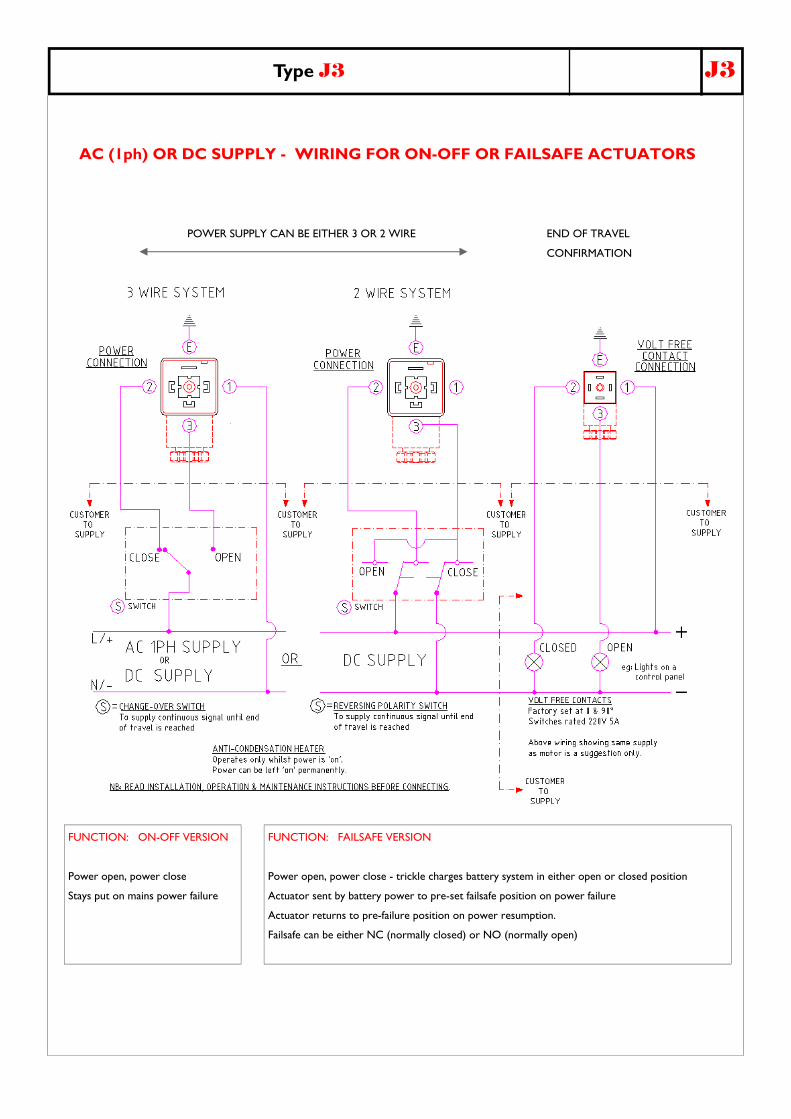
FUNCTION: FAILSAFE VERSION
Power open, power close - trickle charges battery system in either open or closed position
Actuator sent by battery power to pre-set failsafe position on power failure
Actuator returns to pre-failure position on power resumption.
Failsafe can be either NC (normally closed) or NO (normally open)
FUNCTION: ON-OFF VERSION
Power open, power close
Stays put on mains power failure
END OF TRAVEL
CONFIRMATION
POWER SUPPLY CAN BE EITHER 3 OR 2 WIRE
AC (1ph) OR DC SUPPLY - WIRING FOR ON-OFF OR FAILSAFE ACTUATORS
Type J3 J3

Type J3 J3
AC (1ph) OR DC SUPPLY - WIRING FOR MODULATING ACTUATORS
CONNECTING PLUG:
END OF TRAVEL
CONFIRMATION
FUNCTION: MODULATING VERSION
Power open, power close - actuator movement controlled by input signal (4-20mA or 0-10VDC)
Standard operation: 4mA or 0V = actuator closed, 20mA or 10V = actuator open (can be reversed)
Standard operation: Actuator closes on loss of control signal, stays put on loss of mains power
Output signal (in same format as supply signal) provided as standard.
AC (1ph) or
DC SUPPLY
CONNECTING PLUG:
POWER SUPPLY
CONNECTING PLUG:
4-20mA or 0-10VDC
CONTROL SIGNALS
(INPUT & OUTPUT)
N / -
+
-