electrically released brake er-825, er-1225 with pin drive
TRANSCRIPT

Electrically Released Brake ER-825, ER-1225 with Pin Drive Armatures for KONE Inc.
Installation & Operating InstructionsP-230-WE819-0466
An Altra Industrial Motion Company
2 Warner Electric • 800-825-9050 P-230-WE • 819-0466
ContentsIntroduction . . . . . . . . . . . . . . . . . . . . . . . . . . . . . 3Installation for ER-825 & 1225 Brakes with Pin Drive . . . . . . . . . . . . . . . . . . . . . . . . . 4Installation for ER-825 Brake with Outside Armature Hub . . . . . . . . . . . . . . . . . . . . . . . . 5Installation for ER-825 Brake with inside Armature Hub & taperlock Bushing . . . . . . . . 8Installation for ER-825 Brake with Inside Armature Hub & no Taperlock Bushing . . . . 11Installation for ER-1225 Brake with Inside Armature Hub . . . . . . . . . . . . . . . . . . . . . . . 14Maintenance Instructions . . . . . . . . . . . . . . . . . . 17Warranty . . . . . . . . . . . . . . . . . . . . . . . Back Page
Failure to follow these instructions may result in product damage, equipment damage, and serious or fatal injury to personnel .
General Information
This service manual tells how to install, adjust, and maintain your Warner Electric brake .
Warner Electric Electrically Released Brakes are high performance, high torque units . To obtain the required performance and life, the brake must be installed exactly in accordance with the instructions of this service manual . After carefully reading these instructions, no assembly or installation difficulties should be encountered .
The Warner Electric warranty does not apply to any unit which is not installed, used, operated and maintained in accordance with Warner Electric’s instructions .
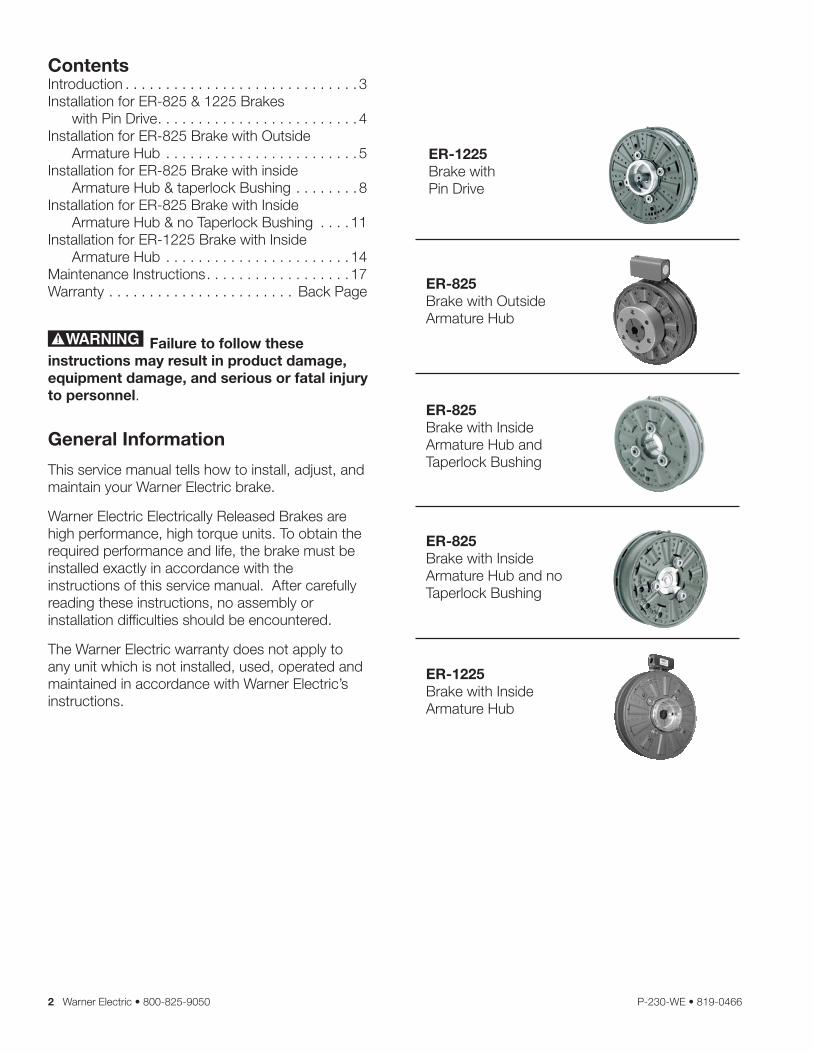
ER-1225Brake withPin Drive
ER-825Brake with OutsideArmature Hub
ER-825Brake with InsideArmature Hub andTaperlock Bushing
ER-825Brake with InsideArmature Hub and no Taperlock Bushing
ER-1225Brake with InsideArmature Hub

Warner Electric • 800-825-9050 P-230-WE • 819-0466 3
Introduction
Warner Electric Electrically Released Brakes function on the same principle of “response to magnetic attraction” that operates other Warner Electric brakes and clutches . Braking torque in the Electrically Released Brake depends on permanent magnets rather than electromagnets . With the power off, the unit produces full braking torque . The brake is released by reversing the direction of flux flow in an electromagnetic coil, thus opposing the field produced by the permanent magnets .
The cancellation of electromagnetic force which releases the brake occurs at one nominal value of ampere turns .
This ampere turn value can vary among brakes because of allowable manufacturing tolerances . Release voltage varies mainly because of the coil tolerance and Autogap® spring variations . Properly adjusting the power supply voltage is important so the autogap springs will separate the magnet and armature, causing full release . If the release voltage is not set properly, the armature will rub against the magnet . This rubbing action can cause the brake and other components in the system to fail . Warner Electric Electrically Released Brakes are burnished at the factory to assure rated torque shortly after initial application . Very little additional wear-in is required .
The same principle of “response to magnetic attraction” used in this FB-650 operates the larger ER-825 and ER-1225 Electrically Released Brakes described in this manual
Autogap®Assembly
Poles
FrictionMaterial
Armature
Coil
PermanentMagnets
Magnet Shell

4 Warner Electric • 800-825-9050 P-230-WE • 819-0466
Installation Instructions for ER-825 &ER-1225 BRAKES With Pin drive
Important: Please read the following cautionary notes before starting installation . The permanent magnets used in this brake which determine its unique features and operation also demand special consideration when installing and operating it . Read the following carefully:
The brake consists of an armature and magnet. The magnet includes permanent magnets which will strongly attract any magnetic material toward it. Keep the magnet at least 1/2 inch away from any magnetic material, including a steel workbench. If the magnet must come closer than 1/2 inch to any magnetic material, keep all body parts clear of the possible contact area to avoid injury. Magnetic attraction can be overcome by applying approximately 90 volts DC to the size 1225 magnet.
To prevent accidents, follow the proper KONE Inc. instructions to lock the escalator in place when installing or replacing a brake.
Each brake is preburnished at the factory & shipped with its mated components. Do not exchange armature or magnet with any other brake as the non-mated components may produce less than rated torque and may cause the escalator to fail. When either component is replaced, the complete brake must be replaced.
If the magnet mounting surface is magnetic material, the magnet must be isolated approximately 1/4 inch from that surface with a plate or spacers of non-magnetic material. This helps to reduce stray magnetic force (flux) which may impair the brake’s operation.
In order to minimize stray flux, the brake should be as exposed as possible or, if enclosed, it must be placed in a housing of non-magnetic material such as 302-304 stainless steel or aluminum .
The mounting pilot diameter must be concentric to the shaft within .010” T .I .R The magnet mounting surface must be square with the shaft within .006” T .I .R ., measured at the bolt circle . The spacer or mounting adapter used in installation of the brake must be machined to tolerances specified above .
New armatures shipped from the factory are flat to within 0.005 inches and must stay flat within this tolerance to maintain full torque. Any attempt to pry the armature loose from the magnet will distort the armature. When adjusting the armature position, apply any required force only to the hub, not to the outer edge of the armature. Moreover, be careful not to drop the armature for this may also cause distortion.
For proper operation of the brake, apply only DC voltages. If AC power is ever applied to the brake, the magnets will set partially demagnetized and the brake will have to be replaced.
The positive & negative of the power lead must be connected to positive & negative lead wires or terminals of the brake, respectively .
Heat: Excessive heat and high operating temperatures are causes of rapid wear . Air should circulate around the unit as freely as possible, especially if the application requires fast, repetitive cycling .
If a choice of armature shaft material exists, it should be non-magnetic . Materials such as type 302-304 stainless have been used very successfully .
Please follow these instructions carefully to ensure proper operation. Failure to comply with these instructions can result in damage to property and injury or even death to personnel.
Warner Electric • 800-825-9050 P-230-WE • 819-0466 5
Tools required (not included)
- 1/4” Hex key wrench for taper lock bushing set screws - ER-1225 .
- 3/16” Hex key wrench for taper lock bushing set screws - ER-825 .
- 7/32” Hex key wrench for mounting screws .- Loctite grade 242 .- Snap ring pliers, external .- Torque wrench minimum 200 lb .ft . reading -
ER-825 .- Torque wrench minimum 400 lb .ft . reading -
ER-1225 .- 3 steel shims, equal thickness, not less than
1/16”, not greater than 1/8” .- Small hammer (approximately 8 ounce) .- Brass Drift .- Flat blade screwdriver .
INSTALLATION FOR ER-825BRAKE WITH OUTSIDEARMATURE HUB
Technical Information:
Static Torque: . . . . . . . . . . . . . . . . . . . . . 125 lb .ft .Max RPM: . . . . . . . . . . . . . . . . . . . . . . . . . . . 3600Voltage: . . . . . . . . . . . . . . . . . . . . . . . . . . .90 VDCTotal weight: . . . . . . . . . . . . . . . . . . . . . . . 15 .6 lb .Current draw - Nominal: . . .0 .295 amp @ 90 VoltsResistance at 20 degrees C: . . 0 .305 ohms ±10%
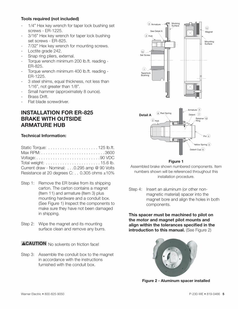
Step 1: Remove the ER brake from its shipping carton . The carton contains a magnet (Item 11) and armature (Item 3) plus mounting hardware and a conduit box . (See Figure 1) Inspect the components to make sure they have not been damaged in shipping .
Step 2: Wipe the magnet and its mounting surface clean and remove any burrs .
No solvents on friction face!
Step 3: Assemble the conduit box to the magnet in accordance with the instructions furnished with the conduit box .
Step 4: Insert an aluminum (or other non-magnetic material) spacer into the magnet bore and align the holes in both components .
This spacer must be machined to pilot on the motor and magnet pilot mounts and align within the tolerances specified in the introduction to this manual. (See Figure 2)
Detail A
Hub
6
Red Spring
RetainerRing
Pin
Armature
Yellow Spring
Detent
Detent Cup
8
10
4
3
5
2
7
Magnet
11
1
Set Screw12
See Detail A
Hub
Armature3
2
TaperlockBushing
WorkingSurface
MountingSurface
Figure 1Assembled brake shown numbered components . Item
numbers shown will be referenced throughout this installation procedure .
Figure 2 - Aluminum spacer installed

6 Warner Electric • 800-825-9050 P-230-WE • 819-0466
Step 5: Position the aluminum spacer/magnet assembly on the motor pilots and align the holes in the spacer with the holes in the motor and magnet . Following the manufacturer’s instructions, apply grade 242 Loctite to the threads of each furnished cap screw, add a lock washer, and fasten the spacer/brake assembly on the motor . Tighten these screws to 25 to 28 lb .ft . torque with a torque wrench .
Make the electrical connection . The positive and negative of the power lead must be connected to the positive and negative lead wires or terminals of the brake, respectively . Follow KONE Inc .instructions to set the release voltage of the brake . Step 6: Place the armature hub assembly on a flat
surface with the armature’s working face up . Push down on each detent cup (Item 6) with your fingers, sliding the armature down until the armature will move no further . (See Figure 3)
Armatureworkingsurface
Figure 3 - Positioning detent cups in armature.
Step 7: Insert the taperlock bushing (item 1) into the hub (Item 2) . Align the two half-drilled holes in the taperlock bushing with the two half-threaded holes in the hub . Insert two set screws (Item 12) into the aligned holes and screw them in loosely to maintain alignment during assembly . (See Figure 1)
During Steps 8, 9, and 10, handle the armature/hub assembly by the hub (Item 2) only, making sure the armature (Item 3) is as close to the hub (Item 2) as possible. Any movement of the armature on the pins (Item 4) will reduce available armature travel and may cause improper air gap setting.
Keep fingers clear of the area between the magnet (Item 11) and the armature (Item 3) because the armature will be pulled sharply toward the magnet after the gap is closed to approximately 1/8 inch. Injury can result if fingers are pinched between the armature and the magnet.
Step 8: Insert the key into the motor shaft key way .
Step 9: Make sure no power is applied to the brake . Place three steel shims 120 degrees apart on the magnet as shown in Figure 4 .
0.062 inch shims are recommended. Do not use shims thicker than 0.125 inch or you will shorten the brake life by reducing available armature travel.
Slip the armature hub assembly onto the motor shaft until the armature makes contact with the shims . (See Figure 4) Using a drift, lightly tap on the taperlock bushing at several points around the circumference with a small hammer until it will not slide further onto the shaft . (See Figure 5)
Figure 4 - Installing armature with shims in place.
Keep fingers away from this area
Shims
Warner Electric • 800-825-9050 P-230-WE • 819-0466 7
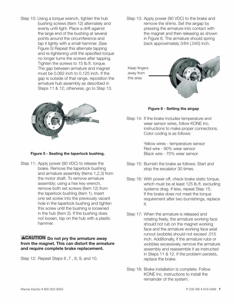
Step 10: Using a torque wrench, tighten the hub bushing screws (Item 12) alternately and evenly until tight . Place a drift against the large end of the bushing at several points around the circumference and tap it lightly with a small hammer . (See Figure 5) Repeat this alternate tapping and re-tightening until the specified torque no longer turns the screws after tapping . Tighten the screws to 15 lb .ft . torque . The gap between armature and magnet must be 0 .062 inch to 0 .125 inch . If the gap is outside of that range, reposition the armature hub assembly as described in Steps 11 & 12; otherwise, go to Step 13 .
Figure 5 - Seating the taperlock bushing.
Step 11: Apply power (90 VDC) to release the brake . Remove the taperlock bushing and armature assembly (Items 1,2,3) from the motor shaft . To remove armature assembly; using a hex key wrench, remove both set screws (Item 12) from the taperlock bushing (Item 1) . Insert one set screw into the previously vacant hole in the taperlock bushing and tighten this screw until the bushing is loosened in the hub (Item 2) . If the bushing does not loosen, tap on the hub with a plastic hammer .
Do not pry the armature away from the magnet. This can distort the armature and require complete brake replacement.
Step 12: Repeat Steps 6 ,7 , 8, 9, and 10 .
Step 13: Apply power (90 VDC) to the brake and remove the shims . Set the airgap by pressing the armature into contact with the magnet and then releasing as shown in Figure 6 . The armature should spring back approximately 3/64 ( .045) inch .
Keep fingers away from this area
Figure 6 - Setting the airgap
Step 14: If the brake includes temperature and wear sensor wires, follow KONE Inc . instructions to make proper connections . Color coding is as follows:
Yellow wires - temperature sensor Red wire - 90% wear sensor Black wire - 70% wear sensor
Step 15: Burnish the brake as follows: Start and stop the escalator 30 times .
Step 16: With power off, check brake static torque, which must be at least 125 lb .ft . excluding systems drag . If less, repeat Step 15 . If the brake does not meet the torque requirement after two burnishings, replace it .
Step 17: When the armature is released and rotating freely, the armature working face should not rub on the magnet working face and the armature working face axial runout (wobble) should not exceed .015 inch . Additionally, if the armature rubs or wobbles excessively, remove the armature assembly and reassemble it as instructed in Steps 11 & 12 . If the problem persists, replace the brake .
Step 18: Brake installation is complete . Follow KONE Inc . instructions to install the remainder of the system .
8 Warner Electric • 800-825-9050 P-230-WE • 819-0466
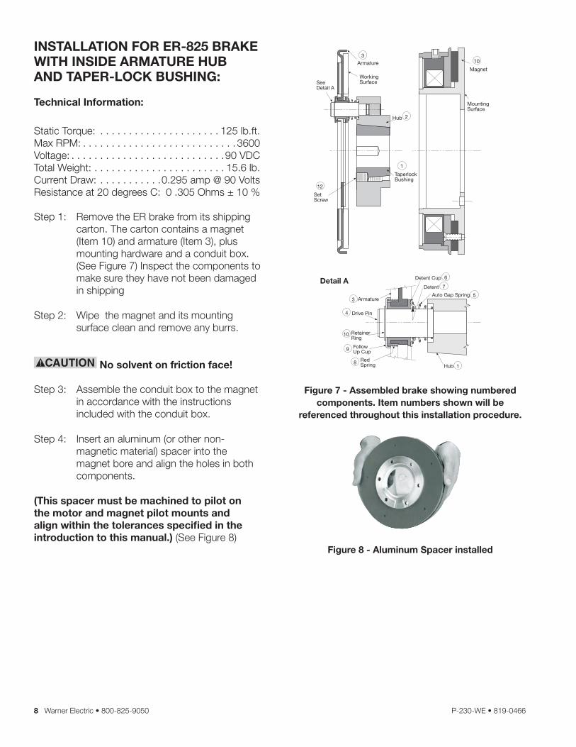
INSTALLATION FOR ER-825 BRAKEWITH INSIDE ARMATURE HUB AND TAPER-LOCK BUSHING:
Technical Information:
Static Torque: . . . . . . . . . . . . . . . . . . . . . 125 lb .ft .Max RPM: . . . . . . . . . . . . . . . . . . . . . . . . . . . 3600Voltage: . . . . . . . . . . . . . . . . . . . . . . . . . . .90 VDCTotal Weight: . . . . . . . . . . . . . . . . . . . . . . . 15 .6 lb .Current Draw: . . . . . . . . . . .0 .295 amp @ 90 VoltsResistance at 20 degrees C: 0 .305 Ohms ± 10 %
Step 1: Remove the ER brake from its shipping carton . The carton contains a magnet (Item 10) and armature (Item 3), plus mounting hardware and a conduit box . (See Figure 7) Inspect the components to make sure they have not been damaged in shipping
Step 2: Wipe the magnet and its mounting surface clean and remove any burrs .
No solvent on friction face!
Step 3: Assemble the conduit box to the magnet in accordance with the instructions included with the conduit box .
Step 4: Insert an aluminum (or other non-magnetic material) spacer into the magnet bore and align the holes in both components .
(This spacer must be machined to pilot on the motor and magnet pilot mounts and align within the tolerances specified in the introduction to this manual.) (See Figure 8)
Figure 7 - Assembled brake showing numbered components. Item numbers shown will be
referenced throughout this installation procedure.
Figure 8 - Aluminum Spacer installed
Detail A
FollowUp Cup
RetainerRing
Drive Pin
ArmatureAuto Gap Spring
Detent
Detent Cup
10
9
4
35
6
7
Hub 1RedSpring8
Magnet
10
See Detail A
Armature
SetScrew
TaperlockBushing
3
12
Hub 2
1
WorkingSurface
MountingSurface
Warner Electric • 800-825-9050 P-230-WE • 819-0466 9
Step 5: Position the magnet/spacer assembly on the motor pilot and align the holes in the magnet with the spacer and mounting surface holes . Following the manufacturer’s instructions, apply grade 242 Loctite to the threads of each furnished cap screw, add a lock washer, and fasten the spacer/magnet assembly on the motor . Tighten these screws to 25 to 28 lb .ft . torque with a torque wrench .
Make the electrical connection . The positive and negative of the power lead must be connected to the positive and negative lead wires or terminals of the brake, respectively . Follow KONE Inc .instructions to set the release voltage of the brake .
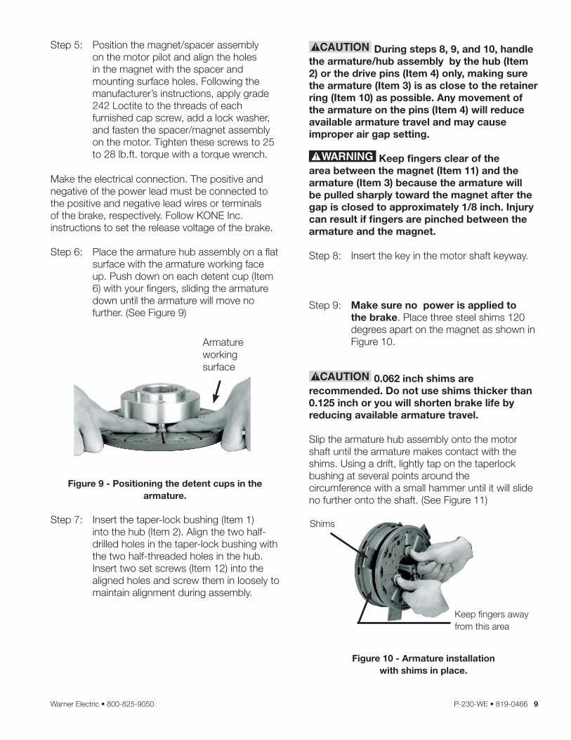
Step 6: Place the armature hub assembly on a flat surface with the armature working face up . Push down on each detent cup (Item 6) with your fingers, sliding the armature down until the armature will move no further . (See Figure 9)
Armature working surface
Figure 9 - Positioning the detent cups in the armature.
Step 7: Insert the taper-lock bushing (Item 1) into the hub (Item 2) . Align the two half-drilled holes in the taper-lock bushing with the two half-threaded holes in the hub . Insert two set screws (Item 12) into the aligned holes and screw them in loosely to maintain alignment during assembly .
During steps 8, 9, and 10, handle the armature/hub assembly by the hub (Item 2) or the drive pins (Item 4) only, making sure the armature (Item 3) is as close to the retainer ring (Item 10) as possible. Any movement of the armature on the pins (Item 4) will reduce available armature travel and may cause improper air gap setting.
Keep fingers clear of the area between the magnet (Item 11) and the armature (Item 3) because the armature will be pulled sharply toward the magnet after the gap is closed to approximately 1/8 inch. Injury can result if fingers are pinched between the armature and the magnet.
Step 8: Insert the key in the motor shaft keyway .
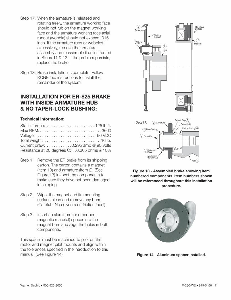
Step 9: Make sure no power is applied to the brake . Place three steel shims 120 degrees apart on the magnet as shown in Figure 10 .
0.062 inch shims are recommended. Do not use shims thicker than 0.125 inch or you will shorten brake life by reducing available armature travel.
Slip the armature hub assembly onto the motor shaft until the armature makes contact with the shims . Using a drift, lightly tap on the taperlock bushing at several points around the circumference with a small hammer until it will slide no further onto the shaft . (See Figure 11)
Figure 10 - Armature installation with shims in place.
Keep fingers awayfrom this area
Shims

10 Warner Electric • 800-825-9050 P-230-WE • 819-0466
Step 10: Using a torque wrench, tighten the hub bushing screws (Item 12) alternately and evenly until tight . Place a drift against the large end of the bushing at several points around the circunference and tap it lightly with a small hammer . (See Figure 11) Repeat this alternate tapping and re-tightening until the specified torque no longer turns the screws after tapping . Tigh ten the screws to 15 lb .ft . torque . The gap between armature and magnet must be 0 .062” to 0 .125 inch . If the gap is outside of that range, reposition the armature hub assembly as described in Steps 11 & 12; otherwise, go to Step 13 .
Figure 11 - Seating the taperlock bushing.
Step 11: Apply power (90 VDC) to release the brake . Remove the taperlock bushing and armature assembly (Items 1,2,3) from the motor . With a hex key wrench, remove both set screws (Item 12) from the taperlock bushing (Item 1) . Insert one set screw into the previously vacant hole in the taperlock bushing and tighten this screw until the bushing is loosened in the hub (Item 2) . If the bushing does not loosen, tap on the hub with a drift and small hammer .
Do not pry the armature away from the magnet. This can distort the armature and require complete brake replacement.
Step 12: Repeat Steps 6, 7, 8, 9, &10 .
Step 13: Make the electrical connections . Apply power (90VDC) to the brake and remove the shims . Set the airgap by pressing the armature into contact with the magnet and then releasing as shown in Figure 12 . The armature should spring back approximately 3/64 ( .045) inch when power is applied to the magnet .
Keep fingers awayfrom this area
Figure 12 - Setting the airgap.
Step 14: If the brake includes temperature and wear sensor wires, follow KONE Inc . instructions to make proper connections . Color coding is as follows:
Yellow wires - temperature sensor Red wire - 90% wear sensor Black wire - 70% wear sensor
Step 15: Burnish the brake as follows: Start and stop the escalator 30 times . Allow 5-10 seconds delay between each start and stop .
Step 16: With power off, check brake static torque, which must be at least 125 lb .ft . If less, repeat Step 15 . If the brake does not meet the torque requirement after two burnishings, replace it .
Warner Electric • 800-825-9050 P-230-WE • 819-0466 11
Step 17: When the armature is released and rotating freely, the armature working face should not rub on the magnet working face and the armature working face axial runout (wobble) should not exceed .015 inch . If the armature rubs or wobbles excessively, remove the armature assembly and reassemble it as instructed in Steps 11 & 12 . If the problem persists, replace the brake .
Step 18: Brake installation is complete . Follow KONE Inc . instructions to install the remainder of the system .
INSTALLATION FOR ER-825 BRAKE WITH INSIDE ARMATURE HUB& NO TAPER-LOCK BUSHING:
Technical Information:
Static Torque: . . . . . . . . . . . . . . . . . . . . . 125 lb .ft .Max RPM: . . . . . . . . . . . . . . . . . . . . . . . . . . . 3600Voltage: . . . . . . . . . . . . . . . . . . . . . . . . . . .90 VDCTotal weight: . . . . . . . . . . . . . . . . . . . . . . . . 16 lb .Current draw: . . . . . . . . . . .0 .295 amp @ 90 VoltsResistance at 20 degrees C: . . 0 .305 ohms ± 10%
Step 1: Remove the ER brake from its shipping carton . The carton contains a magnet (Item 10) and armature (Item 2) . (See Figure 13) Inspect the components to make sure they have not been damaged in shipping
Step 2: Wipe the magnet and its mounting surface clean and remove any burrs . (Careful - No solvents on friction face!)
Step 3: Insert an aluminum (or other non-magnetic material) spacer into the magnet bore and align the holes in both components .
This spacer must be machined to pilot on the motor and magnet pilot mounts and align within the tolerances specified in the introduction to this manual . (See Figure 14)
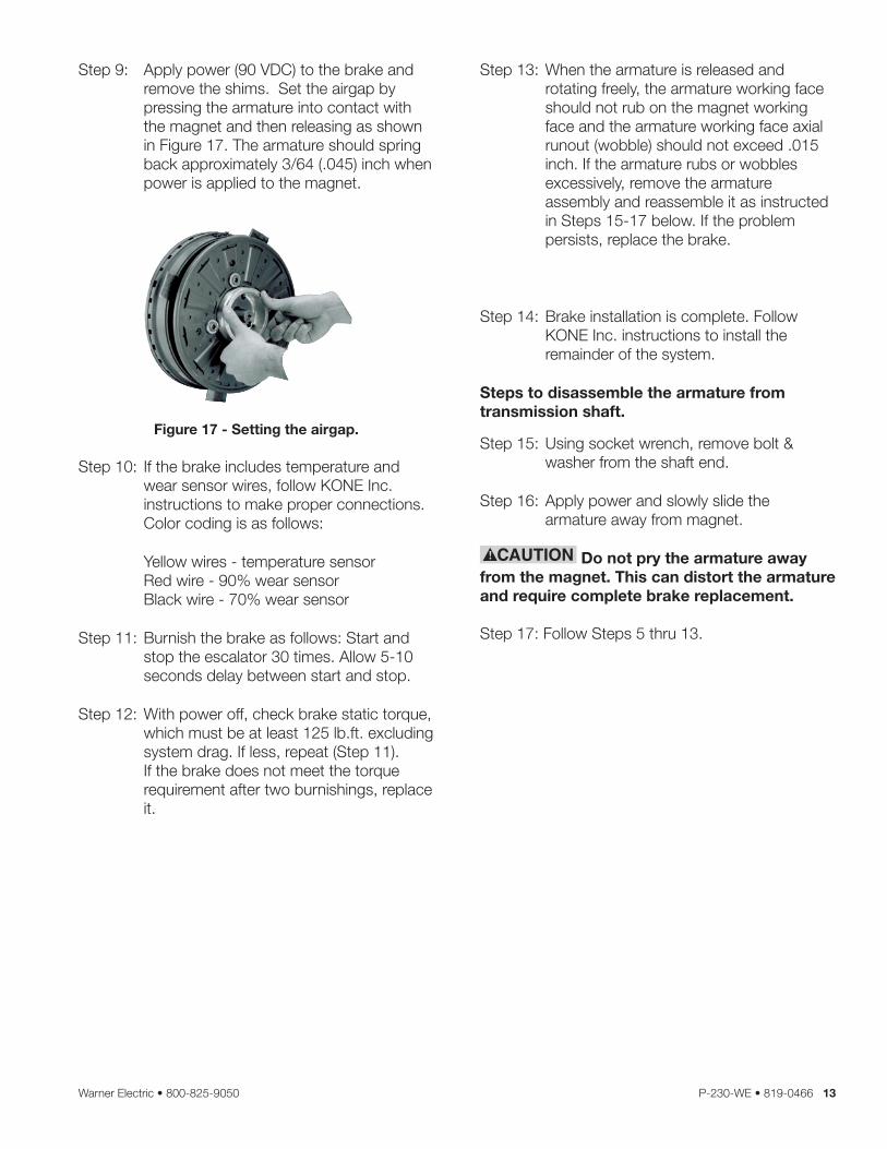
Figure 13 - Assembled brake showing item numbered components. Item numbers shown will be referenced throughout this installation
procedure.
Figure 14 - Aluminum spacer installed.
2
7
56
4
1
10
2
3
Armature
Blue Spring
Drive Pin
RetainerRing
FollowUp Cup
Hub
Yellow Spring
Detent
Detent Cup
Magnet
MountingSurface
WorkingSurface
Armature
SeeDetail A
Detail A
1
9
8
Hub

12 Warner Electric • 800-825-9050 P-230-WE • 819-0466
Step 4: Position the magnet/spacer assembly on the transmission pilot and align the holes in the magnet with the spacer and mounting surface holes . Following the manufacturer’s instructions, apply grade 242 Loctite to the threads of each furnished cap screw, add a lock washer, and fasten the magnet on the transmission . Tighten these screws to 25 to 28 lb .ft . torque with a torque wrench .
Make the elecrical connection . The positive and negative of the power lead must be connected to the positive and negative lead wires or terminals of the brake, respectively . follow KONE Inc .instructions to set the release voltage of the brake .
Step 5: Place the armature hub assembly on a flat surface with the armature working face up . Push down on each detent cup (Item 5) with your fingers, pushing the armature down until the armature will not move down any further . (See Figure 15)
Figure 15 - Positioning the detent cups in the armature.
During steps 7 and 8, handle the armature/hub assembly by the hub (Item 1) only, making sure the armature (Item 2) is as close to the retainer ring (Item 9) as possible. Any movement of the armature on the pins (Item 3) will reduce available armature travel and may cause improper air gap setting.
Keep fingers clear of the area between the magnet (Item 10) and the armature (Item 2) because the armature will be pulled sharply toward the magnet after the gap is closed to approximately 1/8 inch. Injury can result if fingers are pinched between the armature and the magnet.
Step 6: Insert the key in the motor shaft key way .
Step 7: Make sure no power is applied to the brake . Place three steel shims 120 degrees apart on the magnet as shown in Figure 16 .
.062 inch shims are recommended. Do not use shims thicker than .125 inch or you will shorten brake life by reducing available armature travel.
Slip the armature/hub assembly onto the transmission shaft until the armature hub bottoms out on the shims . (See Figure 16) The gap between the armature & magnet must be no more than .125 inch . If the gap is larger than .125 inch, push on the hub to achieve .125 inch gap .
Shims
Figure 16 - Armature installation with shims in place.
Step 8: Insert the washer and bolt into the threaded hole in the end of the shaft . Tighten the bolt to the torque specified by KONE Inc .
Warner Electric • 800-825-9050 P-230-WE • 819-0466 13
Step 9: Apply power (90 VDC) to the brake and remove the shims . Set the airgap by pressing the armature into contact with the magnet and then releasing as shown in Figure 17 . The armature should spring back approximately 3/64 ( .045) inch when power is applied to the magnet .
Figure 17 - Setting the airgap.
Step 10: If the brake includes temperature and wear sensor wires, follow KONE Inc . instructions to make proper connections . Color coding is as follows:
Yellow wires - temperature sensor Red wire - 90% wear sensor Black wire - 70% wear sensor
Step 11: Burnish the brake as follows: Start and stop the escalator 30 times . Allow 5-10 seconds delay between start and stop .
Step 12: With power off, check brake static torque, which must be at least 125 lb .ft . excluding system drag . If less, repeat (Step 11) . If the brake does not meet the torque requirement after two burnishings, replace it .
Step 13: When the armature is released and rotating freely, the armature working face should not rub on the magnet working face and the armature working face axial runout (wobble) should not exceed .015 inch . If the armature rubs or wobbles excessively, remove the armature assembly and reassemble it as instructed in Steps 15-17 below . If the problem persists, replace the brake .
Step 14: Brake installation is complete . Follow KONE Inc . instructions to install the remainder of the system .
Steps to disassemble the armature from transmission shaft.
Step 15: Using socket wrench, remove bolt & washer from the shaft end .
Step 16: Apply power and slowly slide the armature away from magnet .
Do not pry the armature away from the magnet. This can distort the armature and require complete brake replacement.
Step 17: Follow Steps 5 thru 13 .
14 Warner Electric • 800-825-9050 P-230-WE • 819-0466
INSTALLATION FOR ER-1225BRAKE WITH INSIDE ARMATURE HUB
Technical Information:
Static Torque: . . . . . . . . . . . . . . . . . . . . . 400 lb .ft .Max RPM: . . . . . . . . . . . . . . . . . . . . . . . . . . . 3600Voltage: . . . . . . . . . . . . . . . . . . . . . . . . 45-70 VDCTotal weight: . . . . . . . . . . . . . . . . . . . . . . . . 60 lb .Current draw: . . . . . . . . . . . 0 .256 amp @ 60 voltsResistance at 20 degrees C . . . 0 .235 ohms ± 10%
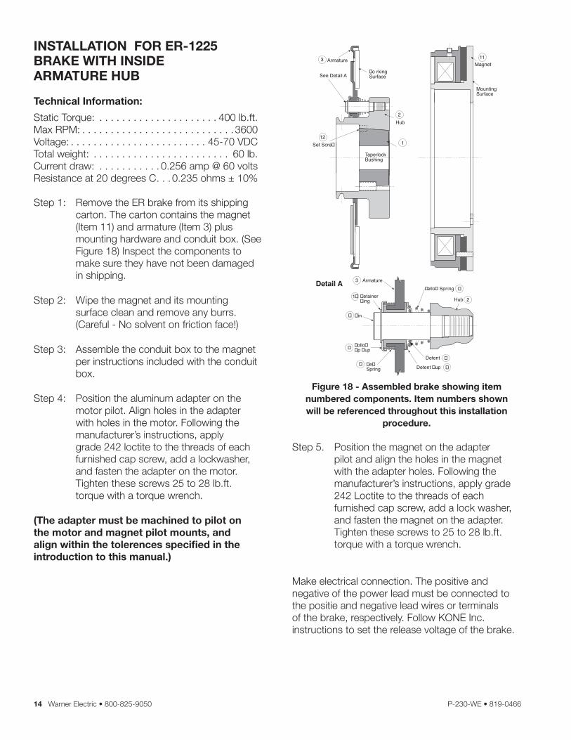
Step 1: Remove the ER brake from its shipping carton . The carton contains the magnet (Item 11) and armature (Item 3) plus mounting hardware and conduit box . (See Figure 18) Inspect the components to make sure they have not been damaged in shipping .
Step 2: Wipe the magnet and its mounting surface clean and remove any burrs . (Careful - No solvent on friction face!)
Step 3: Assemble the conduit box to the magnet per instructions included with the conduit box .
Step 4: Position the aluminum adapter on the motor pilot . Align holes in the adapter with holes in the motor . Following the manufacturer’s instructions, apply grade 242 loctite to the threads of each furnished cap screw, add a lockwasher, and fasten the adapter on the motor . Tighten these screws 25 to 28 lb .ft . torque with a torque wrench .
(The adapter must be machined to pilot on the motor and magnet pilot mounts, and align within the tolerences specified in the introduction to this manual.)
Figure 18 - Assembled brake showing item numbered components. Item numbers shown will be referenced throughout this installation
procedure.
Step 5 . Position the magnet on the adapter pilot and align the holes in the magnet with the adapter holes . Following the manufacturer’s instructions, apply grade 242 Loctite to the threads of each furnished cap screw, add a lock washer, and fasten the magnet on the adapter . Tighten these screws to 25 to 28 lb .ft . torque with a torque wrench .
Make electrical connection . The positive and negative of the power lead must be connected to the positie and negative lead wires or terminals of the brake, respectively . Follow KONE Inc .instructions to set the release voltage of the brake .
Magnet11
MountingSurface
TaperlockBushing
See Detail A
Hub
Armature3
2
Set Scre�12
1
�o rkingSurface
Detail A
�ollo��p �up
�e�Spring
�etainer�ing
�in
Armature�ello� Spr ing
Hub
Detent
Detent �up
�
�
1�
�
3
�
2
�
�
Warner Electric • 800-825-9050 P-230-WE • 819-0466 15
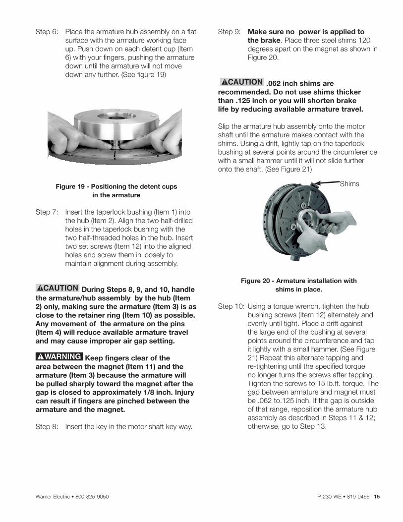
Step 6: Place the armature hub assembly on a flat surface with the armature working face up . Push down on each detent cup (Item 6) with your fingers, pushing the armature down until the armature will not move down any further . (See figure 19)
Figure 19 - Positioning the detent cups in the armature
Step 7: Insert the taperlock bushing (Item 1) into the hub (Item 2) . Align the two half-drilled holes in the taperlock bushing with the two half-threaded holes in the hub . Insert two set screws (Item 12) into the aligned holes and screw them in loosely to maintain alignment during assembly .
During Steps 8, 9, and 10, handle the armature/hub assembly by the hub (Item 2) only, making sure the armature (Item 3) is as close to the retainer ring (Item 10) as possible. Any movement of the armature on the pins (Item 4) will reduce available armature travel and may cause improper air gap setting.
Keep fingers clear of the area between the magnet (Item 11) and the armature (Item 3) because the armature will be pulled sharply toward the magnet after the gap is closed to approximately 1/8 inch. Injury can result if fingers are pinched between the armature and the magnet.
Step 8: Insert the key in the motor shaft key way .
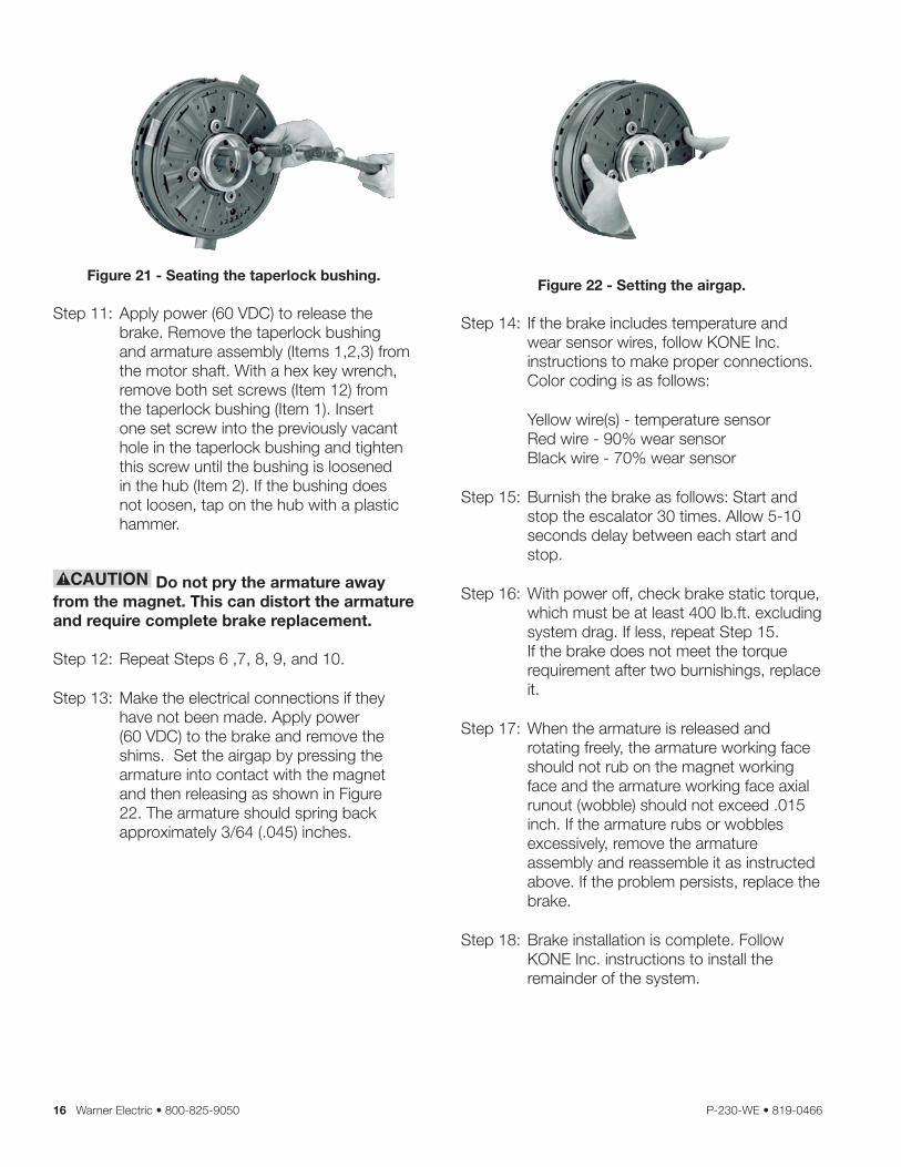
Step 9: Make sure no power is applied to the brake . Place three steel shims 120 degrees apart on the magnet as shown in Figure 20 .
.062 inch shims are recommended. Do not use shims thicker than .125 inch or you will shorten brake life by reducing available armature travel.
Slip the armature hub assembly onto the motor shaft until the armature makes contact with the shims . Using a drift, lightly tap on the taperlock bushing at several points around the circumference with a small hammer until it will not slide further onto the shaft . (See Figure 21)
Shims
Figure 20 - Armature installation with shims in place.
Step 10: Using a torque wrench, tighten the hub bushing screws (Item 12) alternately and evenly until tight . Place a drift against the large end of the bushing at several points around the circumference and tap it lightly with a small hammer . (See Figure 21) Repeat this alternate tapping and re-tightening until the specified torque no longer turns the screws after tapping . Tighten the screws to 15 lb .ft . torque . The gap between armature and magnet must be .062 to .125 inch . If the gap is outside of that range, reposition the armature hub assembly as described in Steps 11 & 12; otherwise, go to Step 13 .
16 Warner Electric • 800-825-9050 P-230-WE • 819-0466
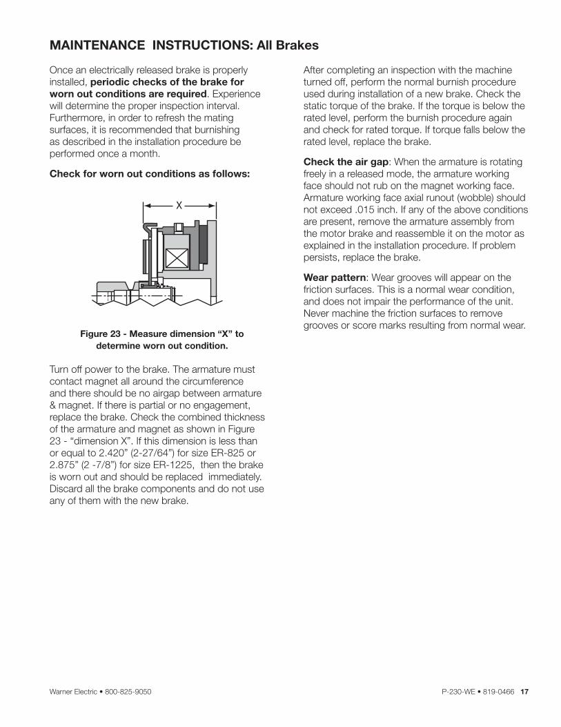
Figure 21 - Seating the taperlock bushing.
Step 11: Apply power (60 VDC) to release the brake . Remove the taperlock bushing and armature assembly (Items 1,2,3) from the motor shaft . With a hex key wrench, remove both set screws (Item 12) from the taperlock bushing (Item 1) . Insert one set screw into the previously vacant hole in the taperlock bushing and tighten this screw until the bushing is loosened in the hub (Item 2) . If the bushing does not loosen, tap on the hub with a plastic hammer .
Do not pry the armature away from the magnet. This can distort the armature and require complete brake replacement.
Step 12: Repeat Steps 6 ,7, 8, 9, and 10 .
Step 13: Make the electrical connections if they have not been made . Apply power (60 VDC) to the brake and remove the shims . Set the airgap by pressing the armature into contact with the magnet and then releasing as shown in Figure 22 . The armature should spring back approximately 3/64 ( .045) inches .
Figure 22 - Setting the airgap.
Step 14: If the brake includes temperature and wear sensor wires, follow KONE Inc . instructions to make proper connections . Color coding is as follows:
Yellow wire(s) - temperature sensor Red wire - 90% wear sensor Black wire - 70% wear sensor
Step 15: Burnish the brake as follows: Start and stop the escalator 30 times . Allow 5-10 seconds delay between each start and stop .
Step 16: With power off, check brake static torque, which must be at least 400 lb .ft . excluding system drag . If less, repeat Step 15 . If the brake does not meet the torque requirement after two burnishings, replace it .
Step 17: When the armature is released and rotating freely, the armature working face should not rub on the magnet working face and the armature working face axial runout (wobble) should not exceed .015 inch . If the armature rubs or wobbles excessively, remove the armature assembly and reassemble it as instructed above . If the problem persists, replace the brake .
Step 18: Brake installation is complete . Follow KONE Inc . instructions to install the remainder of the system .
Warner Electric • 800-825-9050 P-230-WE • 819-0466 17
MAINTENANCE INSTRUCTIONS: All Brakes
Once an electrically released brake is properly installed, periodic checks of the brake for worn out conditions are required . Experience will determine the proper inspection interval . Furthermore, in order to refresh the mating surfaces, it is recommended that burnishing as described in the installation procedure be performed once a month .
Check for worn out conditions as follows:
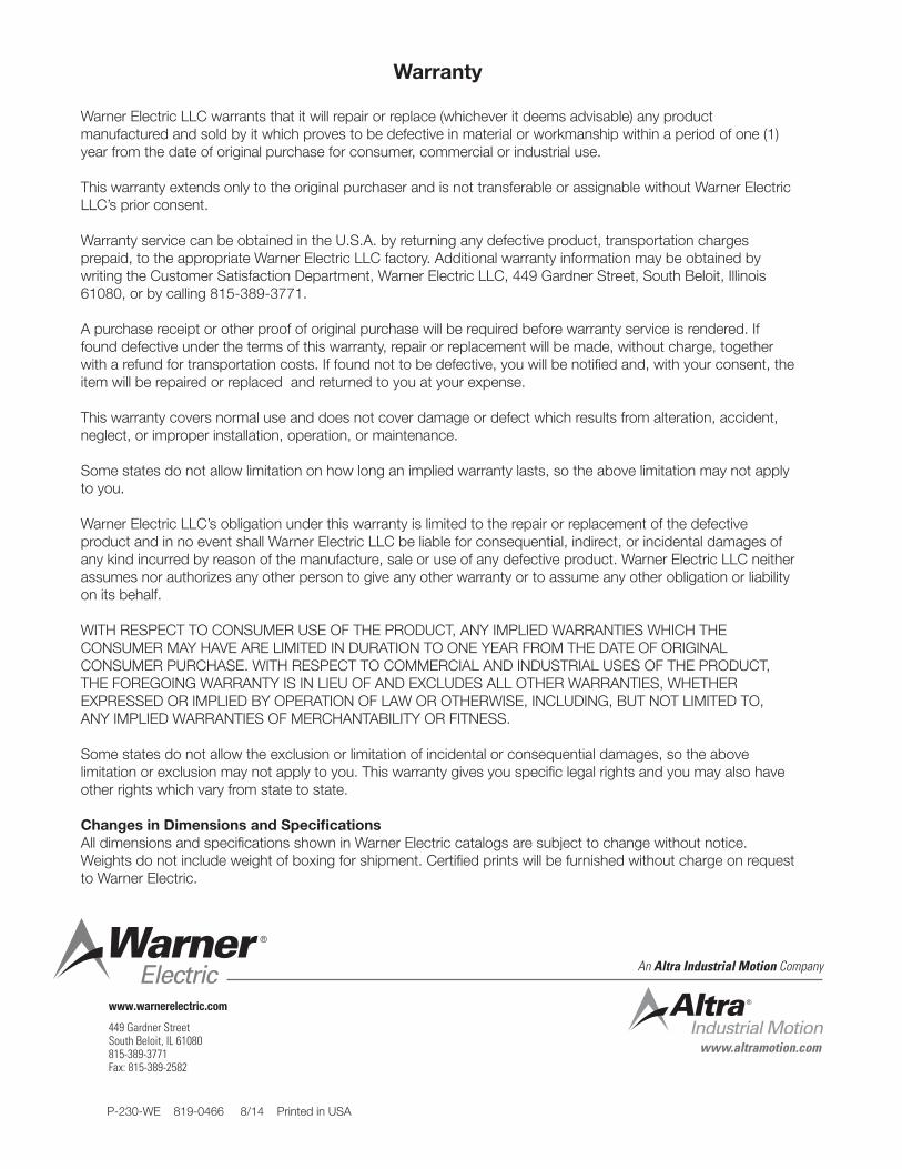
Figure 23 - Measure dimension “X’’ todetermine worn out condition.
Turn off power to the brake . The armature must contact magnet all around the circumference and there should be no airgap between armature & magnet . If there is partial or no engagement, replace the brake . Check the combined thickness of the armature and magnet as shown in Figure 23 - “dimension X” . If this dimension is less than or equal to 2 .420” (2-27/64”) for size ER-825 or 2 .875” (2 -7/8”) for size ER-1225, then the brake is worn out and should be replaced immediately . Discard all the brake components and do not use any of them with the new brake .
After completing an inspection with the machine turned off, perform the normal burnish procedure used during installation of a new brake . Check the static torque of the brake . If the torque is below the rated level, perform the burnish procedure again and check for rated torque . If torque falls below the rated level, replace the brake .
Check the air gap: When the armature is rotating freely in a released mode, the armature working face should not rub on the magnet working face . Armature working face axial runout (wobble) should not exceed .015 inch . If any of the above conditions are present, remove the armature assembly from the motor brake and reassemble it on the motor as explained in the installation procedure . If problem persists, replace the brake .
Wear pattern: Wear grooves will appear on the friction surfaces . This is a normal wear condition, and does not impair the performance of the unit . Never machine the friction surfaces to remove grooves or score marks resulting from normal wear .

18 Warner Electric • 800-825-9050 P-230-WE • 819-0466
NOTES

Warner Electric • 800-825-9050 P-230-WE • 819-0466 19
NOTES
Warranty
Warner Electric LLC warrants that it will repair or replace (whichever it deems advisable) any product manufactured and sold by it which proves to be defective in material or workmanship within a period of one (1) year from the date of original purchase for consumer, commercial or industrial use .
This warranty extends only to the original purchaser and is not transferable or assignable without Warner Electric LLC’s prior consent .
Warranty service can be obtained in the U .S .A . by returning any defective product, transportation charges prepaid, to the appropriate Warner Electric LLC factory . Additional warranty information may be obtained by writing the Customer Satisfaction Department, Warner Electric LLC, 449 Gardner Street, South Beloit, Illinois 61080, or by calling 815-389-3771 .
A purchase receipt or other proof of original purchase will be required before warranty service is rendered . If found defective under the terms of this warranty, repair or replacement will be made, without charge, together with a refund for transportation costs . If found not to be defective, you will be notified and, with your consent, the item will be repaired or replaced and returned to you at your expense .
This warranty covers normal use and does not cover damage or defect which results from alteration, accident, neglect, or improper installation, operation, or maintenance .
Some states do not allow limitation on how long an implied warranty lasts, so the above limitation may not apply to you .
Warner Electric LLC’s obligation under this warranty is limited to the repair or replacement of the defective product and in no event shall Warner Electric LLC be liable for consequential, indirect, or incidental damages of any kind incurred by reason of the manufacture, sale or use of any defective product . Warner Electric LLC neither assumes nor authorizes any other person to give any other warranty or to assume any other obligation or liability on its behalf .
WITH RESPECT TO CONSUMER USE OF THE PRODUCT, ANY IMPLIED WARRANTIES WHICH THE CONSUMER MAY HAVE ARE LIMITED IN DURATION TO ONE YEAR FROM THE DATE OF ORIGINAL CONSUMER PURCHASE . WITH RESPECT TO COMMERCIAL AND INDUSTRIAL USES OF THE PRODUCT, THE FOREGOING WARRANTY IS IN LIEU OF AND EXCLUDES ALL OTHER WARRANTIES, WHETHER EXPRESSED OR IMPLIED BY OPERATION OF LAW OR OTHERWISE, INCLUDING, BUT NOT LIMITED TO, ANY IMPLIED WARRANTIES OF MERCHANTABILITY OR FITNESS .
Some states do not allow the exclusion or limitation of incidental or consequential damages, so the above limitation or exclusion may not apply to you . This warranty gives you specific legal rights and you may also have other rights which vary from state to state .
Changes in Dimensions and SpecificationsAll dimensions and specifications shown in Warner Electric catalogs are subject to change without notice . Weights do not include weight of boxing for shipment . Certified prints will be furnished without charge on request to Warner Electric .
www.altramotion.com
An Altra Industrial Motion Company
P-230-WE 819-0466 8/14 Printed in USA
www.warnerelectric.com
449 Gardner StreetSouth Beloit, IL 61080815-389-3771Fax: 815-389-2582