electrification of diesel-hydraulic off-road machine1165923/fulltext01.pdf · electrification of...
TRANSCRIPT
Electrification of Diesel-Hydraulic Off-road Machine
DHRUV PHADKE
Master of Science Thesis
Stockholm, Sweden 2017

Acknowledgements
I would like to thank Skogforsk and the Forestry Thesis School for providing
the excellent opportunity of working on this thesis.
Without the instrumental support and guidance from my thesis supervisor
Ulf Sellgren of KTH Machine Design department as well as from Olle
Gelin and Fredrik Henriksen of Skogfork, this Thesis would not have been
possible.
Dhruv Phadke
Stockholm, June 2017

Master of Science Thesis MMK 2017:186 MKN 204
Electrification of a diesel-hydraulic off-road machine
Dhruv Phadke
Approved
2017-11-30
Examiner
Ulf Sellgren
Supervisor
Ulf Sellgren
Commissioner
Skogforsk
Contact person
Olle Gelin
Abstract This report is for the Master of Science thesis project undertaken for KTH Royal Institute of
Technology in collaboration with the Forestry Research Institute of Sweden (Skogforsk) for
the Forestry Master Thesis School.
The aim of this project was to theoretically explore the possibility of replacing the hydraulic
driveline with an electric series driveline and to understand the differences between using one
or the other so that it can be convincingly concluded if a Diesel-electric driveline in Forestry
forwarders is a worthwhile endeavour or not.
In this report, the current status of the XT28 driveline is explored as well as improvements in
terms of energy storage, energy recovery and controls are suggested. These two concepts are
quantified and compared against a theoretical Diesel-Electric driveline, with details about its
different parts from Power source to Motors and Gearboxes discussed at length. These three
concepts are compared against each other in terms of Physical characteristics like mass,
Performance characteristics like efficiency, energy recovery, energy storage capacity, etc. and
Practical characteristics like cost. According to the results of the multiple weighted Pugh
matrix comparisons, the theorized Diesel-Electric Driveline holds an edge over even the
improved/idealised version of the current XT28 driveline, despite being hampered by the
cost.
In conclusion, electrification of XT28 is definitely a possibility for the future, only major
concern being the high cost associated with it. The efficiency improvements possible through
use of hybrid electric driveline are significant, with mass difference between the two concepts
much lower than initially expected. However, since most of the performance will depend
heavily on control systems and practical losses, the only way to concretely prove the
efficiency advantage is through detailed computer modelling or manufacturing prototype.
Keywords: driveline control, efficiency, energy storage, XT28

Examensarbete MMK 2017:186 MKN 204
Elektrifiering av en diesel-hydraulisk terrängmaskin
Dhruv Phadke
Godkänd
2017-11-30
Examinator
Ulf Sellgren
Handledare
Ulf Sellgren
Uppdragsgivare
Skogforsk
Kontaktperson
Olle Gelin
Sammanfattning Denna avhandling är resultatet av ett examensarbete för en masterexamen i
maskinkonstruktion vid KTH Kungliga Tekniska Högskolan. Examensarbetet har bedrivits
på uppdrag av det svenska skogsbrukets forskningsinstitut Skogforsk.
Syftet med detta projekt var att teoretiskt undersöka möjligheten att ersätta den hydrauliska
drivlinan i fullskaleprototypen XT28 med en diesel-elektrisk och för att förstå fördelarna och
nackdelarna med att använda den ena, samt att försöka värdera möjligheterna och nyttan med
diesel-elektriska drivlinor i skogsmaskiner. I denna rapport undersöks status för nuvarande
drivlina. Vidare, föreslås potentiella förbättringar när det gäller energilagring,
energiåtervinning och reglering. Dessa egenskaper kvantifieras och jämförs med en teoretisk
diesel-electrisk drivlina, med dess viktigaste komponenter från kraftkälla till motorer och
växellådor. De tre egenskaperna jämförs med varandra med avseende på fysiska egenskaper
som massa, samt prestandaegenskaper, som effektivitet, energiåtervinning,
energilagringskapacitet etc., och även andra egenskaper som kostnad.
Resultaten av de multipelviktade Pugh-matrisjämförelserna visar att den teoretiska diesel-
elektriska drivelinan är något bättre än en förbättrad / idealiserad version av den nuvarande
drivlinan, trots den högre kostnaden. Sammanfattningsvis är elektrifiering av XT28 definitivt
en framtida möjlighet, med den höga kostnaden som en hämmande faktor.
Effektiviseringsförbättringar genom användning av hybrid-elektrisk drivlina är potentiellt
signifikanta, med en betydligt mindre skillnad i totalvikt än vad som förväntades.
Eftersom prestandan starkt beror på styrsystemet och de verkliga förlusterna är det enda sättet
att konkret påvisa de förväntade effektivitetsfördelarna genom mera detaljerade
modellsimuleringar och/eller tillverkning och prov med en fullskaleprototyp.
Nyckelord: drivlina, energilagring, reglering, XT28, verkningsgrad
Contents
1 Introduction 1
1.1 Background . . . . . . . . . . . . . . . . . . . . . . . . . . . . . . . . 1
1.2 Project Aim . . . . . . . . . . . . . . . . . . . . . . . . . . . . . . . . 2
1.3 Scope . . . . . . . . . . . . . . . . . . . . . . . . . . . . . . . . . . . 3
1.4 Methodology . . . . . . . . . . . . . . . . . . . . . . . . . . . . . . . 4
1.5 Outline . . . . . . . . . . . . . . . . . . . . . . . . . . . . . . . . . . . 5
2 XT28 Prototype Driveline 6
2.1 XT28 system description . . . . . . . . . . . . . . . . . . . . . . . . . 6
2.2 XT28 Driveline . . . . . . . . . . . . . . . . . . . . . . . . . . . . . . 8
2.2.1 Power source: Engine . . . . . . . . . . . . . . . . . . . . . . . 8
2.2.2 Inaccessible Power . . . . . . . . . . . . . . . . . . . . . . . . 9
2.2.3 Gear-Boxes . . . . . . . . . . . . . . . . . . . . . . . . . . . . 10
2.2.4 Hydraulic Loops . . . . . . . . . . . . . . . . . . . . . . . . . 10
2.2.4.1 Hydraulic Fluid . . . . . . . . . . . . . . . . . . . . . 11
2.2.4.2 Hydraulic Lines . . . . . . . . . . . . . . . . . . . . . 11
2.2.4.3 Hydraulic Pumps . . . . . . . . . . . . . . . . . . . . 11
2.2.4.4 Hydraulic Motors . . . . . . . . . . . . . . . . . . . . 12
2.2.5 Wheels and Tyres . . . . . . . . . . . . . . . . . . . . . . . . . 12
2.2.6 Controllers . . . . . . . . . . . . . . . . . . . . . . . . . . . . . 12
2.2.7 Cooling Package . . . . . . . . . . . . . . . . . . . . . . . . . . 13
2.2.8 Analysis of XT28 Driveline . . . . . . . . . . . . . . . . . . . . 13
2.2.8.1 Physical Characteristics . . . . . . . . . . . . . . . . 13
2.2.8.2 Practicality Characteristics . . . . . . . . . . . . . . 15
3 Improved Diesel-Hydraulic Concept 17
3.1 Possible improvements in XT28 . . . . . . . . . . . . . . . . . . . . . 17
3.1.1 Accumulator . . . . . . . . . . . . . . . . . . . . . . . . . . . . 17
iii
3.1.1.1 Accumulator Selection . . . . . . . . . . . . . . . . . 18
3.1.1.2 Alternative control algorithm with engine shut-off . . 20
3.1.2 Control Algorithms . . . . . . . . . . . . . . . . . . . . . . . . 21
3.1.2.1 Secondary Control . . . . . . . . . . . . . . . . . . . 21
3.1.2.2 Pressure Control . . . . . . . . . . . . . . . . . . . . 21
3.1.2.3 Speed Control . . . . . . . . . . . . . . . . . . . . . . 22
3.1.2.4 Torque Control . . . . . . . . . . . . . . . . . . . . . 22
3.1.2.5 Flow Limiter . . . . . . . . . . . . . . . . . . . . . . 22
3.1.2.6 Wheel Turn-off . . . . . . . . . . . . . . . . . . . . . 23
3.1.3 Brake Regeneration . . . . . . . . . . . . . . . . . . . . . . . . 23
3.1.4 Concept Architectures . . . . . . . . . . . . . . . . . . . . . . 24
3.2 Analysis of Improved Diesel-Hydraulic Concept . . . . . . . . . . . . 24
3.2.1 Physical Characteristics . . . . . . . . . . . . . . . . . . . . . 24
3.2.2 Performance Characteristics . . . . . . . . . . . . . . . . . . . 26
3.2.3 Practicality Characteristics . . . . . . . . . . . . . . . . . . . . 27
4 Diesel-Electric Concept 28
4.1 Concept Definition . . . . . . . . . . . . . . . . . . . . . . . . . . . . 28
4.1.1 Morphological Chart . . . . . . . . . . . . . . . . . . . . . . . 28
4.1.2 Possible Architectures . . . . . . . . . . . . . . . . . . . . . . 29
4.1.2.1 Series Hybrid . . . . . . . . . . . . . . . . . . . . . . 29
4.1.2.2 Parallel Hybrid . . . . . . . . . . . . . . . . . . . . . 30
4.1.2.3 Series-Parallel Hybrid . . . . . . . . . . . . . . . . . 30
4.1.3 Component Selection . . . . . . . . . . . . . . . . . . . . . . . 31
4.1.3.1 Power Source . . . . . . . . . . . . . . . . . . . . . . 31
4.1.3.2 Power Electronic Converter . . . . . . . . . . . . . . 31
4.1.3.3 Energy Transfer . . . . . . . . . . . . . . . . . . . . 32
4.1.3.4 Energy Storage Device . . . . . . . . . . . . . . . . . 32
4.1.3.5 Inverter . . . . . . . . . . . . . . . . . . . . . . . . . 35
4.1.3.6 Electric Motors . . . . . . . . . . . . . . . . . . . . . 35
4.1.3.7 Gearbox . . . . . . . . . . . . . . . . . . . . . . . . . 36
4.1.4 Final Architecture . . . . . . . . . . . . . . . . . . . . . . . . 37
4.2 Analysis of Diesel-Electric Concept . . . . . . . . . . . . . . . . . . . 39
4.2.1 Physical Characteristics . . . . . . . . . . . . . . . . . . . . . 39
4.2.2 Performance Characteristics . . . . . . . . . . . . . . . . . . . 40
4.2.3 Practicality Characteristics . . . . . . . . . . . . . . . . . . . . 41
iv

5 Concept comparison and discussion 42
5.1 Comparison Method . . . . . . . . . . . . . . . . . . . . . . . . . . . 42
5.1.1 Weighted-Pugh Matrix Selection . . . . . . . . . . . . . . . . . 42
5.1.2 Criteria of Comparison . . . . . . . . . . . . . . . . . . . . . . 43
5.2 Weighted-Pugh Matrix analysis . . . . . . . . . . . . . . . . . . . . . 46
5.2.1 Matrix Creation: First run . . . . . . . . . . . . . . . . . . . . 46
5.2.2 Reasoning and Discussion . . . . . . . . . . . . . . . . . . . . 46
5.2.3 Matrix Creation: Confirmation run . . . . . . . . . . . . . . . 47
5.2.4 Reasoning and Discussion . . . . . . . . . . . . . . . . . . . . 48
5.2.5 Results of Comparison . . . . . . . . . . . . . . . . . . . . . . 49
6 Conclusion 50
6.1 Conclusion . . . . . . . . . . . . . . . . . . . . . . . . . . . . . . . . . 50
6.2 Future Work . . . . . . . . . . . . . . . . . . . . . . . . . . . . . . . . 51
A Component Details 52
A.1 Engine . . . . . . . . . . . . . . . . . . . . . . . . . . . . . . . . . . . 52
A.2 Pump and Motors . . . . . . . . . . . . . . . . . . . . . . . . . . . . . 53
A.2.1 Pump . . . . . . . . . . . . . . . . . . . . . . . . . . . . . . . 53
A.2.2 Motor . . . . . . . . . . . . . . . . . . . . . . . . . . . . . . . 53
A.3 Accumulator Calculations . . . . . . . . . . . . . . . . . . . . . . . . 55
A.3.1 Introduction to Accumulators . . . . . . . . . . . . . . . . . . 55
A.3.2 Nomenclature . . . . . . . . . . . . . . . . . . . . . . . . . . . 56
A.3.3 Relevant Formulae and Calculations . . . . . . . . . . . . . . . 56
B Mass distribution 60
B.1 XT28 Mass distribution . . . . . . . . . . . . . . . . . . . . . . . . . 60
B.2 Improved XT28 mass distribution . . . . . . . . . . . . . . . . . . . . 60
B.3 Diesel-Electric Driveline mass distribution . . . . . . . . . . . . . . . 63
B.4 Mass comparison . . . . . . . . . . . . . . . . . . . . . . . . . . . . . 64
Bibliography 66
v
List of Figures
1.1 Harvester and Forwarder . . . . . . . . . . . . . . . . . . . . . . . . . 2
1.2 Skogforsk XT28 Forwarder . . . . . . . . . . . . . . . . . . . . . . . . 3
1.3 The criteria to compare concepts against . . . . . . . . . . . . . . . . 4
2.1 Skogforsk XT28 Forwarder . . . . . . . . . . . . . . . . . . . . . . . . 6
2.2 Frames/Bodies and Active Suspension . . . . . . . . . . . . . . . . . 7
2.3 XT28 driveline architecture . . . . . . . . . . . . . . . . . . . . . . . 7
2.4 SisuDiesel Citius 84 CTA-4V Engine . . . . . . . . . . . . . . . . . . 9
2.5 Simplified hydraulic circuit for XT28 driveline . . . . . . . . . . . . . 10
2.6 Hydraulic Fluid Viscosity versus Temperature graph . . . . . . . . . . 11
2.7 Displacement Settings and speed with respect to time . . . . . . . . . 13
2.8 Component weights and their distribution in XT28 driveline . . . . . 14
2.9 Actual and Reference speed with Sequential Control . . . . . . . . . . 15
3.1 Bosch Raxroth AG Bladder-type accumulator . . . . . . . . . . . . . 18
3.2 Comparison of HYDAC accumulators with different volumes . . . . . 19
3.3 The behaviour of the system with a baseline thermostatic SOC control 20
3.4 Secondary Control: Simplified Circuit diagram . . . . . . . . . . . . . 21
3.5 Flow Limiter: Saturation limit dependant on how many wheels that
are in use versus the speed . . . . . . . . . . . . . . . . . . . . . . . . 22
3.6 Regenerative braking in hydraulic driveline . . . . . . . . . . . . . . . 23
3.7 Improved Diesel-Hydraulic Concept Architecture . . . . . . . . . . . . 25
3.8 Component weights and their distribution in improved hydraulic driveline 25
3.9 Result of simple simulation for XT28 . . . . . . . . . . . . . . . . . . 27
4.1 The generic driveline system structure . . . . . . . . . . . . . . . . . 28
4.2 Basic Morphological Chart . . . . . . . . . . . . . . . . . . . . . . . . 28
4.3 Series Hybrid Architecture for XT28 . . . . . . . . . . . . . . . . . . 29
4.4 Converter controlled electrical machine and secondary energy storage 31
4.5 Overview of different electrochemical energy storage types . . . . . . 33
vi
4.6 Ragone diagram . . . . . . . . . . . . . . . . . . . . . . . . . . . . . . 34
4.7 Characteristic parameters of Hybrid Energy Storage . . . . . . . . . . 35
4.8 Series HEV system configuration with back-to-back diode-clamped multilevel
converters . . . . . . . . . . . . . . . . . . . . . . . . . . . . . . . . . 36
4.9 SUMO MD series of AC motor-invereter combinations . . . . . . . . . 37
4.10 Basic Morphological Chart with selected components . . . . . . . . . 37
4.11 Final Architecture of Diesel-Electric Driveline . . . . . . . . . . . . . 38
4.12 Component weights and their distribution in Diesel-Electric Concept
driveline . . . . . . . . . . . . . . . . . . . . . . . . . . . . . . . . . . 40
5.1 The criteria to compare concepts against . . . . . . . . . . . . . . . . 43
5.2 The criteria to compare concepts against . . . . . . . . . . . . . . . . 44
5.3 Division of points between different Criteria . . . . . . . . . . . . . . 45
5.4 Weighted-Pugh Matrix Comparison: First Run . . . . . . . . . . . . . 46
5.5 Weighted-Pugh Matrix Comparison: Confirmation Run . . . . . . . . 48
A.1 Engine Curves: Power, Torque, and SFC with respect to Speed[5] . . 52
A.2 Pump Hydromechanical Efficiency . . . . . . . . . . . . . . . . . . . . 54
A.3 Pump Volumetric Efficiency . . . . . . . . . . . . . . . . . . . . . . . 54
A.4 Motor Hydro-mechanical Efficiency . . . . . . . . . . . . . . . . . . . 55
A.5 Motor Volumetric Efficiency . . . . . . . . . . . . . . . . . . . . . . . 55
A.6 Useful data for HYDAC accumulators with different volumes . . . . . 57
A.7 Adiabatic expansion in Bladder accumulator [7] . . . . . . . . . . . . 58
A.8 Comparison of HYDAC accumulators with different volumes . . . . . 58
A.9 Comparison of HYDAC accumulators with different volumes . . . . . 59
B.1 Weight of key components in XT28, with quantity and frame-wise
distribution . . . . . . . . . . . . . . . . . . . . . . . . . . . . . . . . 61
B.2 Component weights and their distribution in XT28 driveline . . . . . 62
B.3 Component weights and their distribution in improved hydraulic driveline 62
B.4 Component weights and their distribution in Diesel-Electric Concept
driveline . . . . . . . . . . . . . . . . . . . . . . . . . . . . . . . . . . 63
B.5 Mass distribution comparison for unloaded vehicle . . . . . . . . . . . 64
B.6 Mass distribution comparison for loaded vehicle . . . . . . . . . . . . 65
vii

Chapter 1
Introduction
1.1 Background
Over 70% of Sweden is covered in forests. Out of that, over 80% is in active use,
providing a vital natural resource for the country. Forest Industry in Sweden is an
important part of the economy, providing employment for more than 70000 people
and an export value of SEK 125 billion, making the country the world’s 3rd largest
exporter of pulp, paper and sawn timber. Investments in the industry are also
very high, at over SEK 17.5 billion invested in 2016 alone. However, despite these
large figures, the Forest industry is also very sustainable, accounting for only 1% of
greenhouse gas emissions and consistently reducing the amount of pollutants released
in the air and water system by the years. This has been possible largely due to
the excess of SEK 4 billion invested annually by the government of Sweden and the
Forest industry itself. This research is essential for the industry to keep providing
economical and high quality product in the global market against our competitors on
the global forum[1].
As in most of the northern European countries, Swedish Forest industry follows the
Cut-To-Length (CTL) logging method to cut trees, which requires the use of two
primary heavy vehicles for the entire process from cutting trees down, chopping them
into logs of desired lengths, and deposit the logs to the nearest point of transportation.
The task of cutting trees into proper length is performed by a machine called ’the
Harvester’, which has a hydraulic arm equipment designed for this express purpose.
The logs cut by the Harvester are then taken out of the forest and next to the roads
by a machine called ’the Forwarder’, which is essentially a log-carrier designed to
work in extreme off-road conditions of the Scandinavian forests. Both the Forwarder
and the Harvester (shown in the Figure 1.1), in their current design, use hydraulic
1
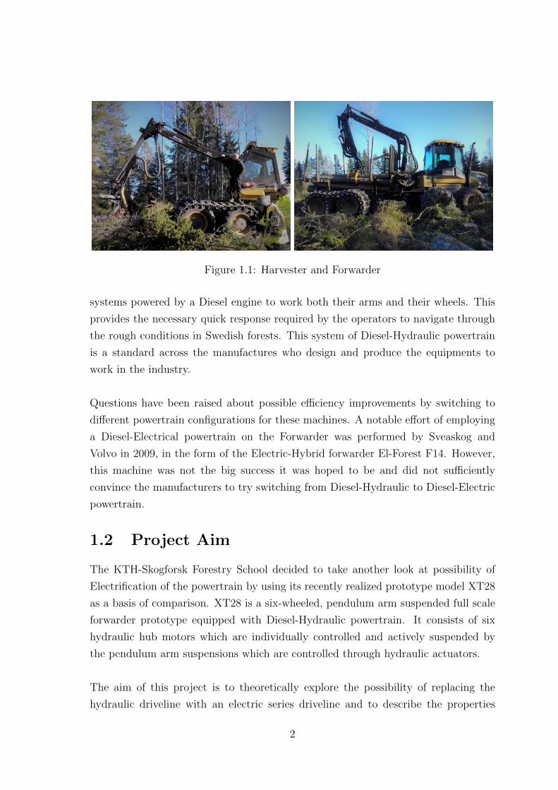
Figure 1.1: Harvester and Forwarder
systems powered by a Diesel engine to work both their arms and their wheels. This
provides the necessary quick response required by the operators to navigate through
the rough conditions in Swedish forests. This system of Diesel-Hydraulic powertrain
is a standard across the manufactures who design and produce the equipments to
work in the industry.
Questions have been raised about possible efficiency improvements by switching to
different powertrain configurations for these machines. A notable effort of employing
a Diesel-Electrical powertrain on the Forwarder was performed by Sveaskog and
Volvo in 2009, in the form of the Electric-Hybrid forwarder El-Forest F14. However,
this machine was not the big success it was hoped to be and did not sufficiently
convince the manufacturers to try switching from Diesel-Hydraulic to Diesel-Electric
powertrain.
1.2 Project Aim
The KTH-Skogforsk Forestry School decided to take another look at possibility of
Electrification of the powertrain by using its recently realized prototype model XT28
as a basis of comparison. XT28 is a six-wheeled, pendulum arm suspended full scale
forwarder prototype equipped with Diesel-Hydraulic powertrain. It consists of six
hydraulic hub motors which are individually controlled and actively suspended by
the pendulum arm suspensions which are controlled through hydraulic actuators.
The aim of this project is to theoretically explore the possibility of replacing the
hydraulic driveline with an electric series driveline and to describe the properties
2
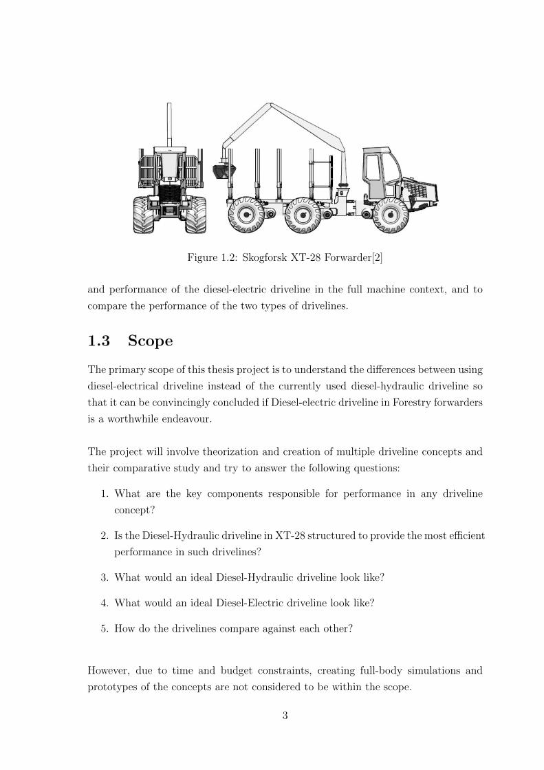
Figure 1.2: Skogforsk XT-28 Forwarder[2]
and performance of the diesel-electric driveline in the full machine context, and to
compare the performance of the two types of drivelines.
1.3 Scope
The primary scope of this thesis project is to understand the differences between using
diesel-electrical driveline instead of the currently used diesel-hydraulic driveline so
that it can be convincingly concluded if Diesel-electric driveline in Forestry forwarders
is a worthwhile endeavour.
The project will involve theorization and creation of multiple driveline concepts and
their comparative study and try to answer the following questions:
1. What are the key components responsible for performance in any driveline
concept?
2. Is the Diesel-Hydraulic driveline in XT-28 structured to provide the most efficient
performance in such drivelines?
3. What would an ideal Diesel-Hydraulic driveline look like?
4. What would an ideal Diesel-Electric driveline look like?
5. How do the drivelines compare against each other?
However, due to time and budget constraints, creating full-body simulations and
prototypes of the concepts are not considered to be within the scope.
3
1.4 Methodology
Objectively measuring the performance drivelines in the era of electronic control is a
near impossibility due to the complex interaction between environment, machine and
control algorithms. Even if two exactly same machines are used, their performance
against each other in different environments employing different control algorithms
will be very dissimilar. Therefore, this thesis will focus on exploring different characteristics
describing the systems and indirectly assessing their performance. These characteristics
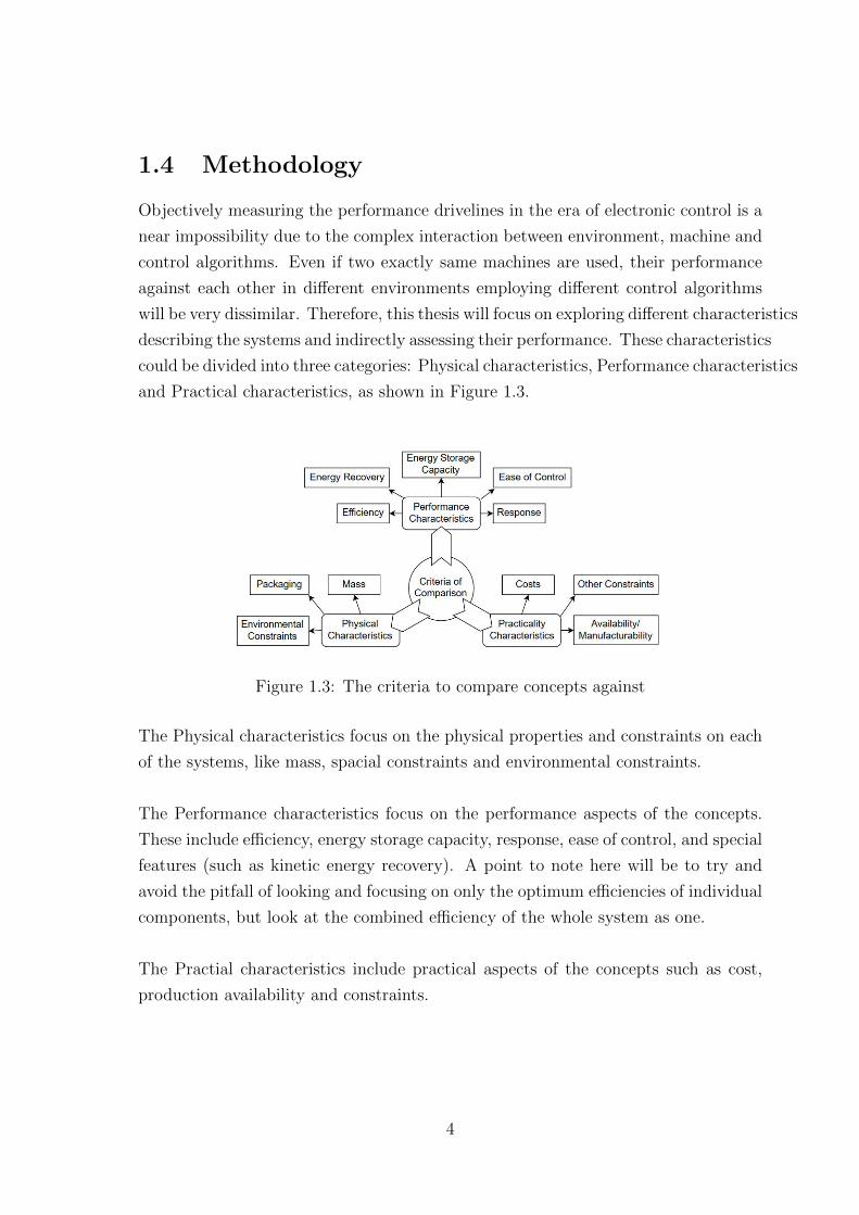
could be divided into three categories: Physical characteristics, Performance characteristics
and Practical characteristics, as shown in Figure 1.3.
Figure 1.3: The criteria to compare concepts against
The Physical characteristics focus on the physical properties and constraints on each
of the systems, like mass, spacial constraints and environmental constraints.
The Performance characteristics focus on the performance aspects of the concepts.
These include efficiency, energy storage capacity, response, ease of control, and special
features (such as kinetic energy recovery). A point to note here will be to try and
avoid the pitfall of looking and focusing on only the optimum efficiencies of individual
components, but look at the combined efficiency of the whole system as one.
The Practial characteristics include practical aspects of the concepts such as cost,
production availability and constraints.
4

1.5 Outline
Chapter 2 will focus on Diesel-Hydraulic driveline in the XT-28 prototype. Chapter
3 will focus on the possible improvements in the Diesel-Hydraulic driveline for a
forwarder and its differences from the XT-28 prototype. Chapter 4 will focus on
a possible Diesel-Electric driveline for forwarder machine and its characteristics.
Chapter 5 will focus on comparison between these drivelines. Chapter 6 will focus on
the conclusions from the study and the possibility of future work.
The appendix A contains relevant data about driveline components such as engine
and hydraulic components, whereas appendix B contains detailed mass comparison
of the concepts.
5
Chapter 2
XT28 Prototype Driveline
2.1 XT28 system description
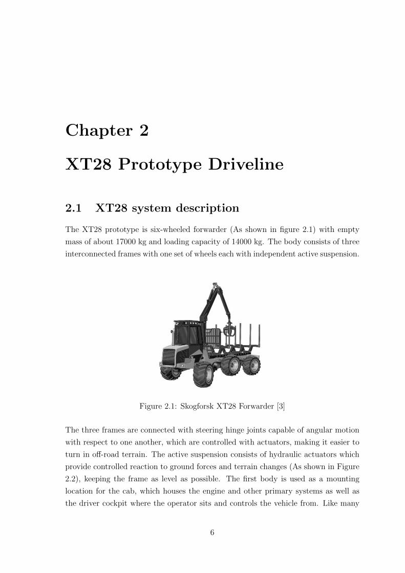
The XT28 prototype is six-wheeled forwarder (As shown in figure 2.1) with empty
mass of about 17000 kg and loading capacity of 14000 kg. The body consists of three
interconnected frames with one set of wheels each with independent active suspension.
Figure 2.1: Skogforsk XT28 Forwarder [3]
The three frames are connected with steering hinge joints capable of angular motion
with respect to one another, which are controlled with actuators, making it easier to
turn in off-road terrain. The active suspension consists of hydraulic actuators which
provide controlled reaction to ground forces and terrain changes (As shown in Figure
2.2), keeping the frame as level as possible. The first body is used as a mounting
location for the cab, which houses the engine and other primary systems as well as
the driver cockpit where the operator sits and controls the vehicle from. Like many
6

Figure 2.2: Frames/Bodies and Active Suspension[3]
other forwarder products, the seat within the cab can rotate 180o to face backwards
so that it’s easier for the controller to observe directly the loading of logs into the
carrier, making the job easier. For this purpose, the cab is fitted with two sets of
dashboards and drive pedals[4].
From this information, the XT28 architecture can be described as a series hybrid.
(See Figure 2.3)
Figure 2.3: XT28 driveline architecture
Since the prototype is designed to be used as an aid for study projects, it is incorporated
7
with several sensors and equipments such as:
• Two Drive Pedals
• Two Brake Pedals
• Two high pressure sensors in each circuit
• A speed sensor attached to each wheel shaft
• An angle sensor in each frame joint
• Parking brake
2.2 XT28 Driveline
The XT28 driveline is a series Diesel-Hydraulic Hybrid driveline, where the input
is provided by an engine which, in turn, powers the hydraulic circuits which power
the motors on each wheel. Since the Hydraulic components used can vary their
displacement settings, the whole system is highly controllable, with better efficiency
than standard mechanical systems, especially in the off-road conditions of Swedish
forests.
2.2.1 Power source: Engine
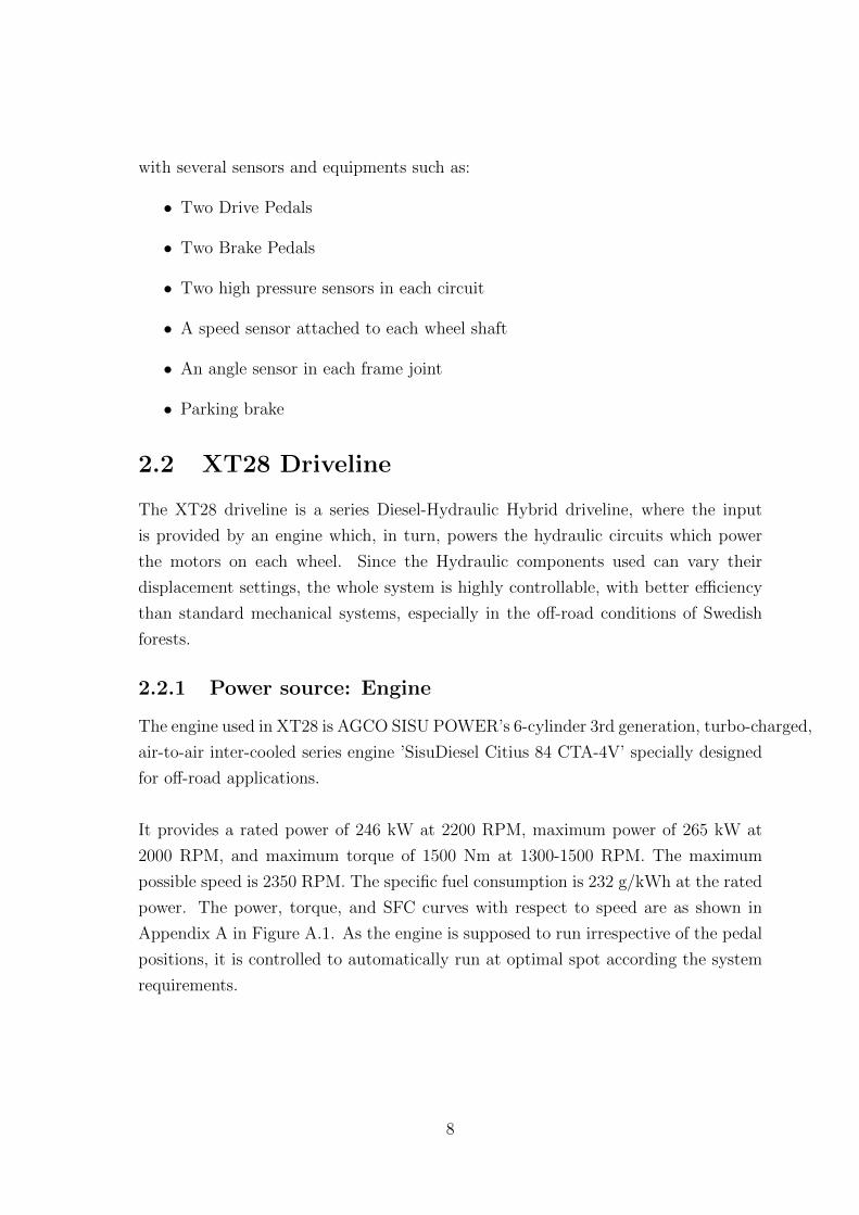
The engine used in XT28 is AGCO SISU POWER’s 6-cylinder 3rd generation, turbo-charged,
air-to-air inter-cooled series engine ’SisuDiesel Citius 84 CTA-4V’ specially designed
for off-road applications.
It provides a rated power of 246 kW at 2200 RPM, maximum power of 265 kW at
2000 RPM, and maximum torque of 1500 Nm at 1300-1500 RPM. The maximum
possible speed is 2350 RPM. The specific fuel consumption is 232 g/kWh at the rated
power. The power, torque, and SFC curves with respect to speed are as shown in
Appendix A in Figure A.1. As the engine is supposed to run irrespective of the pedal
positions, it is controlled to automatically run at optimal spot according the system
requirements.
8
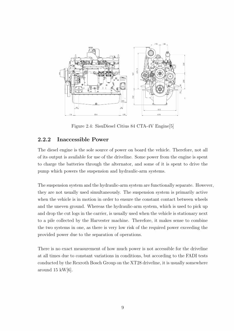
Figure 2.4: SisuDiesel Citius 84 CTA-4V Engine[5]
2.2.2 Inaccessible Power
The diesel engine is the sole source of power on board the vehicle. Therefore, not all
of its output is available for use of the driveline. Some power from the engine is spent
to charge the batteries through the alternator, and some of it is spent to drive the
pump which powers the suspension and hydraulic-arm systems.
The suspension system and the hydraulic-arm system are functionally separate. However,
they are not usually used simultaneously. The suspension system is primarily active
when the vehicle is in motion in order to ensure the constant contact between wheels
and the uneven ground. Whereas the hydraulic-arm system, which is used to pick up
and drop the cut logs in the carrier, is usually used when the vehicle is stationary next
to a pile collected by the Harvester machine. Therefore, it makes sense to combine
the two systems in one, as there is very low risk of the required power exceeding the
provided power due to the separation of operations.
There is no exact measurement of how much power is not accessible for the driveline
at all times due to constant variations in conditions, but according to the FADI tests
conducted by the Rexroth Bosch Group on the XT28 driveline, it is usually somewhere
around 15 kW[6].
9
2.2.3 Gear-Boxes
The system consists of two sets of fixed ratio gearboxes.
The first is between the engine and the hydraulic pump, called the Pump Splitter
gearbox (As it additionally performs the job of splitting the engine power between
the two pump loops, as explained in the next section). This gearbox is designed to
increase the speed of the shaft to be suitable for the operation of hydraulic pumps.
Therefore, it has a transmission ratio of 0.78 with average experimental efficiency of
0.95[6].
The second gearbox is the Range Gearbox, which is a set situated between each of
the six hydraulic motors on the wheels and the wheel hubs themselves. The purpose
of this gearbox is to reduce the speed from the motor and increase the torque applied
at the wheel. The transmission ratio provided by this gearbox is 48.3 with an average
efficiency of 0.96[6].
2.2.4 Hydraulic Loops
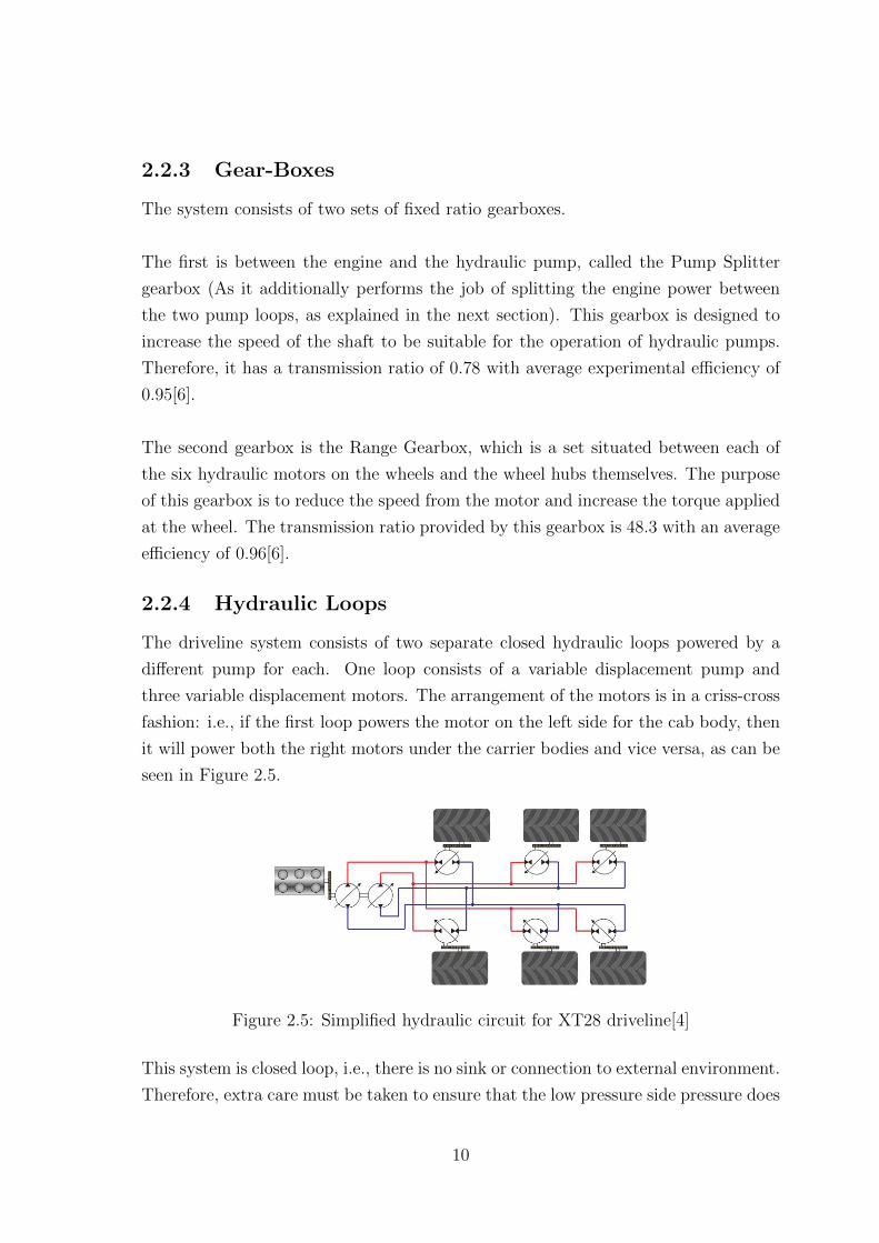
The driveline system consists of two separate closed hydraulic loops powered by a
different pump for each. One loop consists of a variable displacement pump and
three variable displacement motors. The arrangement of the motors is in a criss-cross
fashion: i.e., if the first loop powers the motor on the left side for the cab body, then
it will power both the right motors under the carrier bodies and vice versa, as can be
seen in Figure 2.5.
Figure 2.5: Simplified hydraulic circuit for XT28 driveline[4]
This system is closed loop, i.e., there is no sink or connection to external environment.
Therefore, extra care must be taken to ensure that the low pressure side pressure does
10
not drop to vacuum due to excessive pull from the pump. This is done by adding
boost pressure pump to keep a consistently maintain certain minimum pressure at
the low-pressure side of the loop.
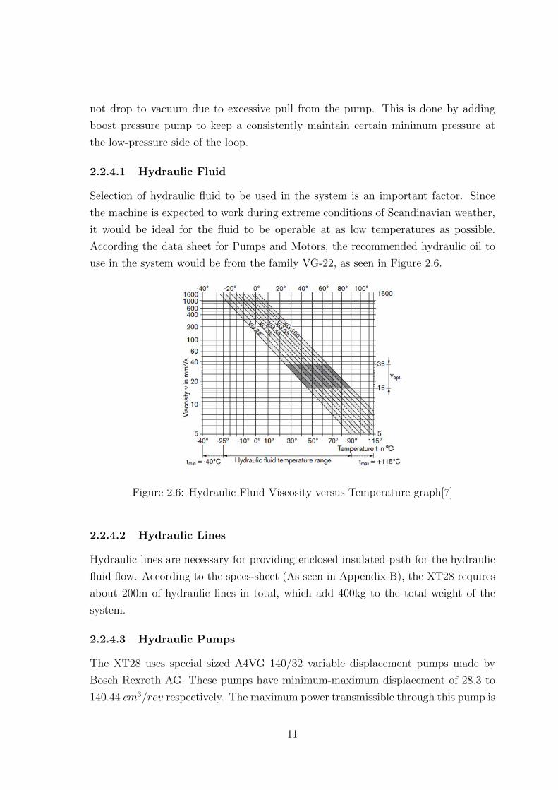
2.2.4.1 Hydraulic Fluid
Selection of hydraulic fluid to be used in the system is an important factor. Since
the machine is expected to work during extreme conditions of Scandinavian weather,
it would be ideal for the fluid to be operable at as low temperatures as possible.
According the data sheet for Pumps and Motors, the recommended hydraulic oil to
use in the system would be from the family VG-22, as seen in Figure 2.6.
Figure 2.6: Hydraulic Fluid Viscosity versus Temperature graph[7]
2.2.4.2 Hydraulic Lines
Hydraulic lines are necessary for providing enclosed insulated path for the hydraulic
fluid flow. According to the specs-sheet (As seen in Appendix B), the XT28 requires
about 200m of hydraulic lines in total, which add 400kg to the total weight of the
system.
2.2.4.3 Hydraulic Pumps
The XT28 uses special sized A4VG 140/32 variable displacement pumps made by
Bosch Rexroth AG. These pumps have minimum-maximum displacement of 28.3 to
140.44 cm3/rev respectively. The maximum power transmissible through this pump is
11

257 kW at nominal pressure difference of 400 bar. At the maximum displacement and
pressure, the pump can reach 2700 RPM. At half corner power, the pump can reach
3000 RPM, and the high idling speed at low pressures is 3100 RPM. Maximum torque
transmissible is 891 Nm. Minimum/Stall speed is 500 RPM. Each pump weighs about
82 kg[8].
2.2.4.4 Hydraulic Motors
The XT28 uses A6VM 107/63 variable displacement motors made by Bosch Rexroth
AG at each wheel. These motors have minimum-maximum displacement of 0 to 107
cm3/rev respectively. The maximum power transmissible through this pump is 250
kW at nominal pressure difference of 400 bar. At the maximum displacement and
pressure, the pump can reach 3550 RPM. The high idling speed at low displacements
is 6300 RPM. Maximum torque transmissible is 681 Nm[9].
These motors are uni-directional, which means that they can only run in one direction,
thereby making regeneration from braking difficult to achieve.
2.2.5 Wheels and Tyres
The tyres used are 700/50 R30.5 in all cases with estimated rolling radius of 668mm,
with rim diameter possibly between 700-800mm. This information is important when
considering the packaging of different concepts.
2.2.6 Controllers
The XT28 forwarder, in its current form, uses only a sequential controller and does
not use any of the other controllers.
Sequential controller changes the displacement settings on the pump and the motor
depending on the accelerator pedal position. For the pump, while speed ratio nnmax
is
less than or equal to a certain value, the displacement setting linearly increases from
0 to maximum and after that it stays constant at maximum. Conversely, the motor
displacement setting is initially set at maximum and starts a non-linear decrease at
the same point in time. That point depends on pump and motor efficiencies. The
method of calculating the curves is shown in Modelling and control of a hydraulic
driveline with secondary control” [4] and a graph in Figure 2.7.
12
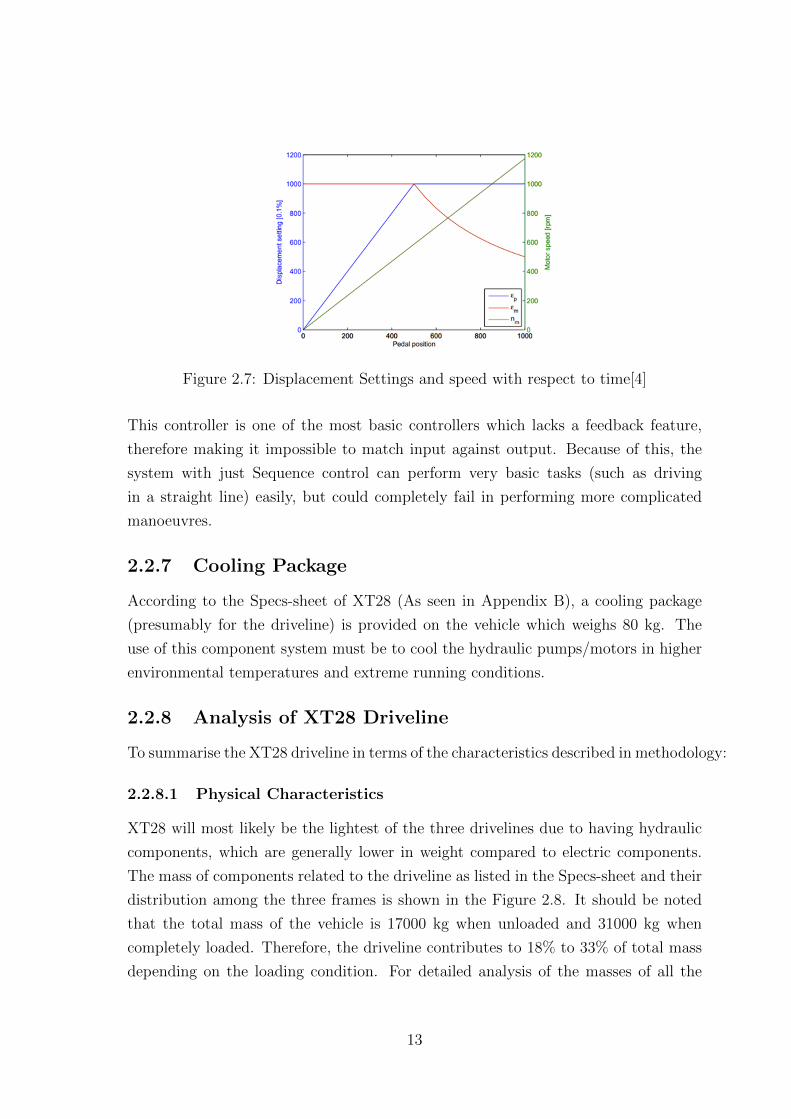
Figure 2.7: Displacement Settings and speed with respect to time[4]
This controller is one of the most basic controllers which lacks a feedback feature,
therefore making it impossible to match input against output. Because of this, the
system with just Sequence control can perform very basic tasks (such as driving
in a straight line) easily, but could completely fail in performing more complicated
manoeuvres.
2.2.7 Cooling Package
According to the Specs-sheet of XT28 (As seen in Appendix B), a cooling package
(presumably for the driveline) is provided on the vehicle which weighs 80 kg. The
use of this component system must be to cool the hydraulic pumps/motors in higher
environmental temperatures and extreme running conditions.
2.2.8 Analysis of XT28 Driveline
To summarise the XT28 driveline in terms of the characteristics described in methodology:
2.2.8.1 Physical Characteristics
XT28 will most likely be the lightest of the three drivelines due to having hydraulic
components, which are generally lower in weight compared to electric components.
The mass of components related to the driveline as listed in the Specs-sheet and their
distribution among the three frames is shown in the Figure 2.8. It should be noted
that the total mass of the vehicle is 17000 kg when unloaded and 31000 kg when
completely loaded. Therefore, the driveline contributes to 18% to 33% of total mass
depending on the loading condition. For detailed analysis of the masses of all the
13

concepts, please refer to Appendix B.
Figure 2.8: Component weights and their distribution in XT28 driveline
As the XT28 is the existing prototype, there is definitely no problem regarding spatial
constraints.
Environmentally speaking, since the temperature in the working conditions can vary
from −30oC to 30oC depending on season and location, the components and systems
used should be able to function in those conditions. For XT28, since it is a working
prototype, it can be assumed that the components in the various hydraulic systems,
electrical systems and mechanical systems are designed or selected according to the
robustness requirements for demands of the weather.
Performance Characteristics
According to the experimental measurements of the efficiency matrices of the pumps
and motors (As shown in Appendix A), the hydraulic components show high efficiency
in very specific scenarios. The volumetric efficiency seems to increase with speed and
displacement, but reduces with pressure. Depending on the situation, it can be as
high as 99.2% or as low as 75.6%. Conversely, the mechanical efficiency has a varying
response with pressure, speed and displacement as well. It varies even more depending
on the situation, from 22.6% (if we ignore stalling) at its lowest to 98.4% at its highest.
Therefore, even if the ideal efficiencies of hydraulic pumps and motors are quite high,
they are only achievable in particular optimal peak situations. The off-road working
14
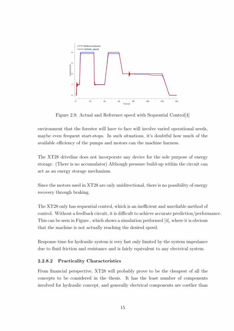
Figure 2.9: Actual and Reference speed with Sequential Control[4]
environment that the forester will have to face will involve varied operational needs,
maybe even frequent start-stops. In such situations, it’s doubtful how much of the
available efficiency of the pumps and motors can the machine harness.
The XT28 driveline does not incorporate any device for the sole purpose of energy
storage. (There is no accumulator) Although pressure build-up within the circuit can
act as an energy storage mechanism.
Since the motors used in XT28 are only unidirectional, there is no possibility of energy
recovery through braking.
The XT28 only has sequential control, which is an inefficient and unreliable method of
control. Without a feedback circuit, it is difficult to achieve accurate prediction/performance.
This can be seen in Figure , which shows a simulation performed [4], where it is obvious
that the machine is not actually reaching the desired speed.
Response time for hydraulic system is very fast only limited by the system impedance
due to fluid friction and resistance and is fairly equivalent to any electrical system.
2.2.8.2 Practicality Characteristics
From financial perspective, XT28 will probably prove to be the cheapest of all the
concepts to be considered in the thesis. It has the least number of components
involved for hydraulic concept, and generally electrical components are costlier than
15
electric components.
The components involved for XT28 are definitely manufacturable since they are
already procured standard components.
16

Chapter 3
Improved Diesel-HydraulicConcept
3.1 Possible improvements in XT28
The XT28 architecture is defined in the previous chapter. However, as stated, the
driveline in XT28 can be improved upon (at least theoretically) by incorporating
more components and concepts within it. The following can be some possible positive
changes to the architecture:
1. Adding an accumulator to the system
2. Improving the control algorithms
3. Adding Kinetic energy regeneration
3.1.1 Accumulator
An accumulator is an energy storing device incorporated in Hydraulic circuits, which
stores excess pump outflow when the requirement at motor end is low and supplements
it when output requirement is high. The recommended type of accumulator to be
used in a system like forester is gas-charged accumulators. These are of two main
types: Bladder type and diaphragm type. From the Bosch Rexroth AG catalog for
accumulators[7] (As seen in Figure 3.1), it can be seen that the biggest available
accumulator is of 50L capacity. Since we have 3 motors with maximum possible flow
of 380L/min in a single circuit, making the maximum flow rate of the accumulator
another important parameter for consideration. Most of the accumulators in the
market provide a flow rate around 15L/s or 900L/min, making sure that any sudden
requirement from the wheels can be quickly satisfied. The mass and dimensions of
17

Figure 3.1: Bosch Raxroth AG Bladder-type accumulator[7]
the accumulator are also important factors to keep in mind. If an accumulator is
included in the hydraulic circuit, it can provide many functions, most importantly:
• Stores power in case of intermittent duty cycles (which is a distinct possibility
for the forwarder in the off-road environment)
• Compensates for leakage loss, thereby improving efficiency of the circuit
• Dampens pulsations due to load changes within the system.
Additionally, with accumulator included in the system, several energy saving schemes
become possible. Firstly, kinetic energy recovery from braking is not a practical
endeavour without accumulator involved to store the excess power returned to the
circuit. This is because without accumulators, the recovered energy can only be stored
in the system in the form of pressure build-up, which may cause problems in some
scenarios. Also, it is possible to adapt a completely different energy conservation
method based on the state of charge of accumulator as explained by Y.Kim, Z. Filipi
in their paper[10].
3.1.1.1 Accumulator Selection
In order to find the right accumulator for the specific system requirements of the
XT28 systems, product data sheets of several manufacturers were examined. Most of
the products from companies were rejected for a multitude of reasons such as:
18
• Stated nominal working pressure below the requirement of the system, which is
400 bar (Bosch, FST, Eaton)
• Working temperature range not satisfactory (Parker)
• Bladder material can’t be used with the hydraulic oil used for XT28 operations
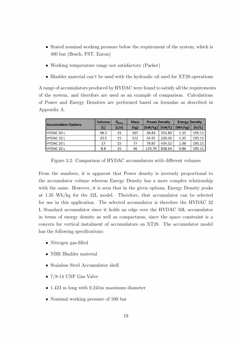
A range of accumulators produced by HYDAC were found to satisfy all the requirements
of the system, and therefore are used as an example of comparison. Calculations
of Power and Energy Densities are performed based on formulae as described in
Appendix A.
Figure 3.2: Comparison of HYDAC accumulators with different volumes
From the numbers, it is apparent that Power density is inversely proportional to
the accumulator volume whereas Energy Density has a more complex relationship
with the same. However, it is seen that in the given options, Energy Density peaks
at 1.35 Wh/kg for the 32L model. Therefore, that accumulator can be selected
for use in this application. The selected accumulator is therefore the HYDAC 32
L Standard accumulator since it holds an edge over the HYDAC 50L accumulator
in terms of energy density as well as compactness, since the space constraint is a
concern for vertical instalment of accumulators on XT28. The accumulator model
has the following specifications:
• Nitrogen gas-filled
• NBR Bladder material
• Stainless Steel Accumulator shell
• 7/8-14 UNF Gas Valve
• 1.423 m long with 0.241m maximum diameter
• Nominal working pressure of 500 bar
19

• Temperature range of −50oC to 50o
As the capacity of accumulator fluid storage required can only be determined after
further testing, the number of accumulators to be used in the circuits can be determined
after more experimentation. Since they will be connected in parallel, such a system
will have the same Energy and Power density values, but more Qmax flow rate.
3.1.1.2 Alternative control algorithm with engine shut-off
Ordinarily in Series Hybrid systems powered by Petrol/Diesel Engines, the algorithms
are designed to actively keep the engine on the ’sweet spot’ where it produces the
desired combination of high power and torque with low emissions, since engine is
usually the least efficient component in the system architecture. However, focusing
on keeping one component at maximized efficiency isn’t the correct method to achieve
system-wide optimization. Therefore it is possible to use an algorithm which aims
to use the state of charge of the accumulator to act as an indicator to control the
system. Instead of keeping the engine running all the time, it is automatically shut
down during low-load cycles.[10] The effect of this logic can be seen in the Figure 3.3.
Figure 3.3: The behaviour of the system with a baseline thermostatic SOC control:a) vehicle speed, and SOC history during the first 350 seconds of the FUDS, and b)pedal position and engine power[10]
This method is modelled for a heavy vehicle in urban environment, and may not be
ideal on our vehicle which needs to traverse in off-road conditions. The idea still has
merit and can be studied further.
20
3.1.2 Control Algorithms
As stated in the previous chapter, the control algorithm used for XT28 is grossly
inadequate to ensure good all-round performance. In addition to the Sequential
Control, following controls could be added to the system[4] to ensure improvement in
performance and behaviour:
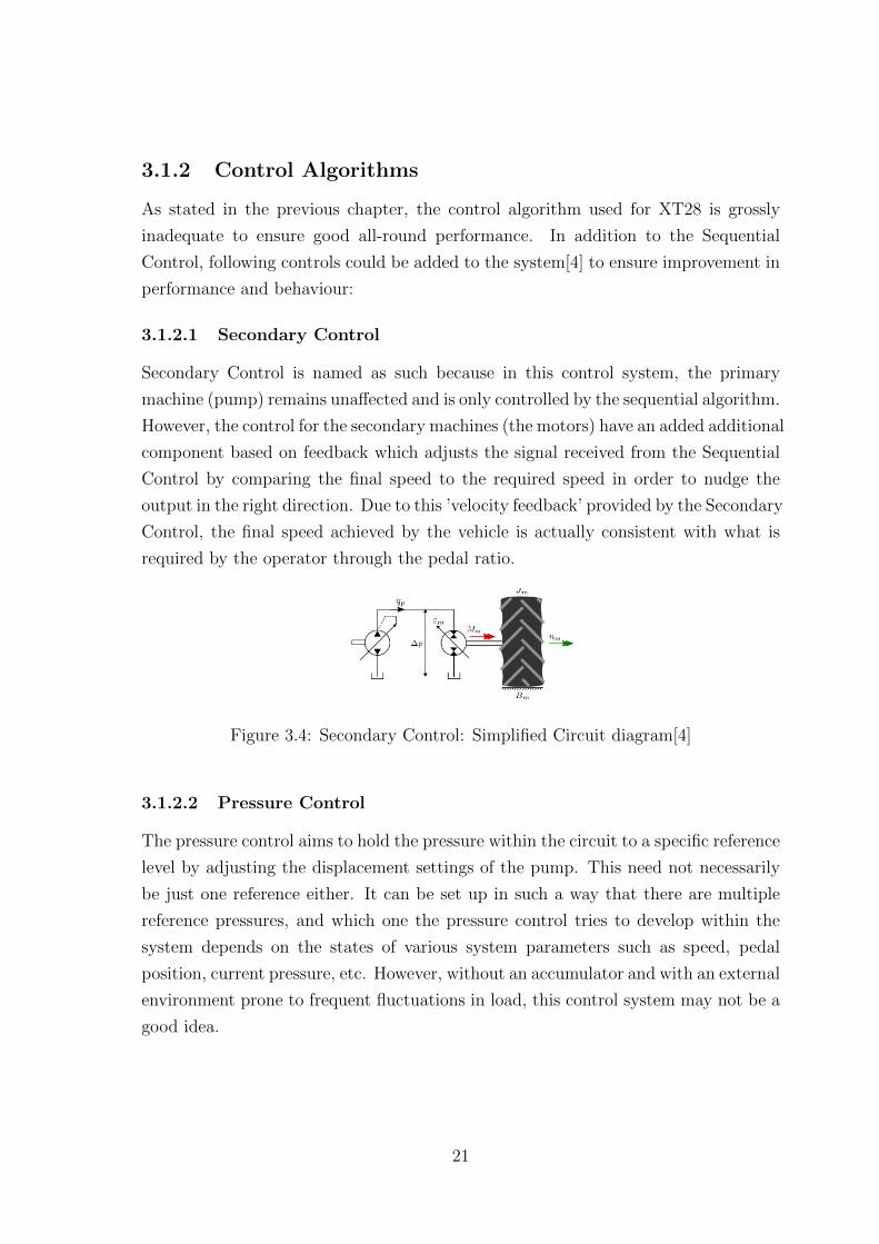
3.1.2.1 Secondary Control
Secondary Control is named as such because in this control system, the primary
machine (pump) remains unaffected and is only controlled by the sequential algorithm.
However, the control for the secondary machines (the motors) have an added additional
component based on feedback which adjusts the signal received from the Sequential
Control by comparing the final speed to the required speed in order to nudge the
output in the right direction. Due to this ’velocity feedback’ provided by the Secondary
Control, the final speed achieved by the vehicle is actually consistent with what is
required by the operator through the pedal ratio.
Figure 3.4: Secondary Control: Simplified Circuit diagram[4]
3.1.2.2 Pressure Control
The pressure control aims to hold the pressure within the circuit to a specific reference
level by adjusting the displacement settings of the pump. This need not necessarily
be just one reference either. It can be set up in such a way that there are multiple
reference pressures, and which one the pressure control tries to develop within the
system depends on the states of various system parameters such as speed, pedal
position, current pressure, etc. However, without an accumulator and with an external
environment prone to frequent fluctuations in load, this control system may not be a
good idea.
21

3.1.2.3 Speed Control
As the name suggests, the speed control is aimed at ensuring that the final speed at
the wheel (assuming to be proportional to the motor) is as close as possible to the one
indicated by the pedal position. Overall, it seems that the function for Speed Control
and Secondary Control have the same target, but very different ways of achieving
it. The Secondary control relies on filters and Laplace transform whereas the Speed
control uses a lead-lag compensator, which also stabilizes the signal by reducing the
probability of having a zero in the denominator of equations.
3.1.2.4 Torque Control
Unlike the other controls, the torque control uses torque at the wheels as a reference
so that the torque requirement for the vehicle is met so as to achieve the desired
speed.
3.1.2.5 Flow Limiter
The hydraulic circuit in the system uses one pump to power three motors. Therefore,
if the motors at high speed also had high displacement setting, they will collectively
demand more flow than what the pump can handle at its best. This is where the Flow
Limiter comes in. It calculates the maximum allowed motor displacement setting and
sets that as a limit to other controllers which are affecting the motor. The general
saturation limits for different wheel turn-off situations (see the next section) are shown
in the Figure 3.5.
Figure 3.5: Flow Limiter: Saturation limit dependant on how many wheels that arein use versus the speed[4]
22

3.1.2.6 Wheel Turn-off
The Forwarder vehicle has to operate in two distinctly different scenarios. One is in
the forest to collect the cut logs. There the terrain is difficult to navigate, speed is low
and high torque is needed. The other scenario is travelling on the open roads, where
the terrain is predictable and flat, with higher speed and lower torque requirements.
This creates an issue due to the flow saturation as mentioned in the previous section.
With all six wheels connected, the maximum limit of pump is such that the vehicle
reaches the saturation at the speed of just 4.8km/hr, after which the displacement
setting is constantly lowered by the Flow Limiter. This results in a very low possible
high speed for the vehicle, which is insufficient to travel on open roads.
This problem is solved by intentionally turning one set of wheels off. This causes
them to freely rotate, and the flow in the circuit which was previously shared by
three motors is now shared by only two. This pushes the saturation limit of the Flow
Limiter higher. This effect can be clearly seen the Figure 3.5.
3.1.3 Brake Regeneration
A hydraulic driveline employing accumulator and variable displacement bi-directional
motor can theoretically recover kinetic energy from braking and store it as either a
pressure increase in the circuit or a flow increase in the accumulator. The system to
achieve this will require a valve for every motor which can readily reverse the flow
direction of the motor when brakes are applied. The idea is easily explained in the
Figure 3.6.
Figure 3.6: Regenerative braking in hydraulic driveline[11]
23

However, there are a few practical difficulties involved in making this system work.
The first is to acquire a bi-directional variable displacement motor. Although, theoretically,
any motor when run backwards will result in acting like a pump, there are several
practical problems involved against this assumption. The primary reason is that a
pump or a motor is specifically designed and optimized to work best in a situation
within design limit of operation. If a motor optimized to work as such is converted
into a pump, not only will it give really bad efficiency, it might also be severely
damaged due to exposure to tasks it wasn’t designed to perform. Acquiring a variable
displacement pump/motors which can provide decent effeciency performing either of
the tasks is a difficult endeavour in itself.
Despite these difficulties, several studies have been successfully performed tests
involving regeneration ([12],[13],[11],[14]). They all provide consistently positive feedback
about regenerative braking, one even claims to have improved the fuel economy by
20% [12] and another claims 30% [11]. It should be noted, however, that these
comparisons are done for road vehicles and they may not necessarily be applicable to
off-road vehicle like the XT28 Forwarder.
3.1.4 Concept Architectures
Considering the possible additions to the already existing XT28 driveline, it is apparent
that additional controllers as well as an accumulator must be added, but the regenerative
braking is a point of debate only due to the fact that the motors required to perform
the job adequately for XT28 system may not be available in the market. However,
since this concept is aimed to be the ’ideal’ form of XT28 Diesel-Hydraulic driveline,
the proposed architecture would look as shown in Figure 3.7
3.2 Analysis of Improved Diesel-Hydraulic Concept
To summarize the improved hydraulic driveline in terms of characteristics described
in the methodology:
3.2.1 Physical Characteristics
The improved hydraulic driveline will be in the middle range of the three drivelines
from the perspective of mass. Due to addition of components, it’s certainly heavier
than XT28, but the difference between the weights of electric components and hydraulic
24
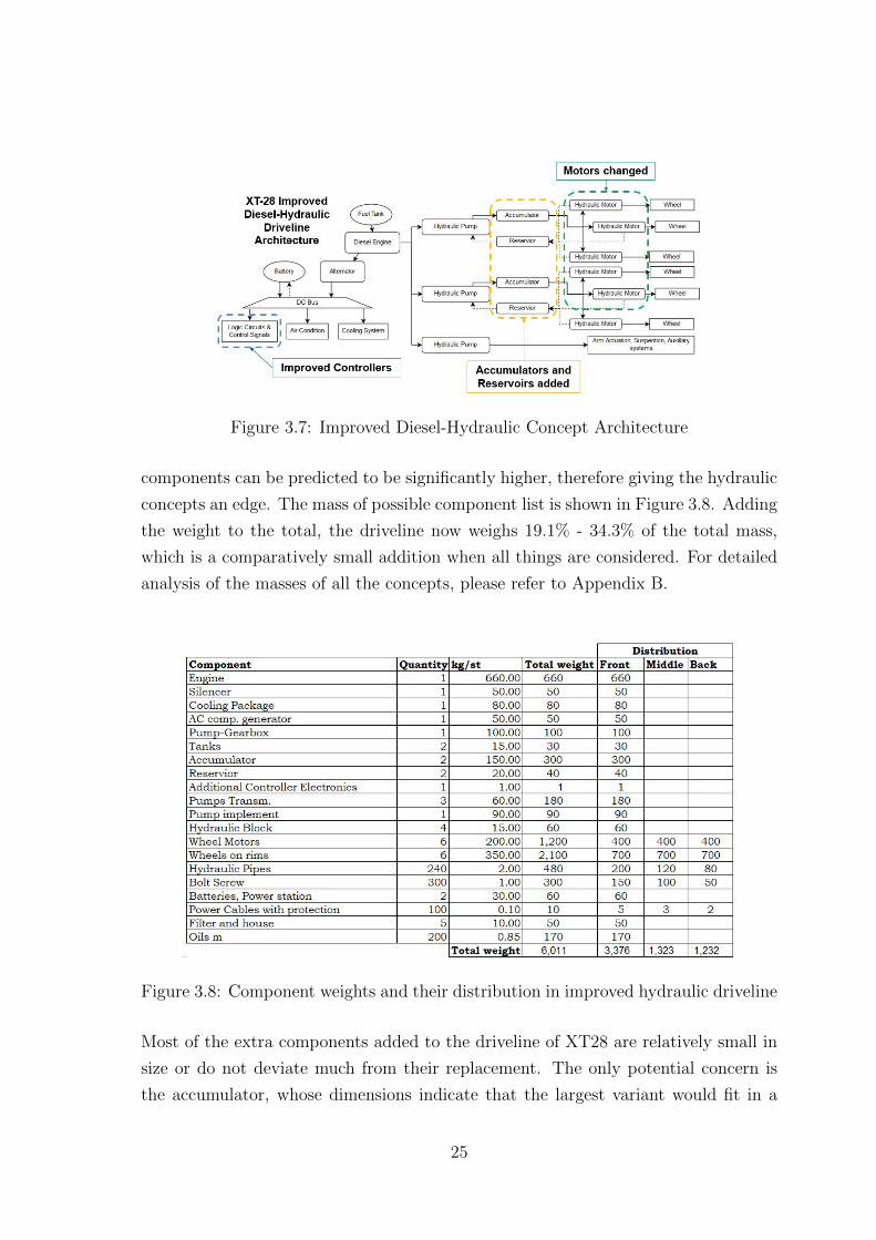
Figure 3.7: Improved Diesel-Hydraulic Concept Architecture
components can be predicted to be significantly higher, therefore giving the hydraulic
concepts an edge. The mass of possible component list is shown in Figure 3.8. Adding
the weight to the total, the driveline now weighs 19.1% - 34.3% of the total mass,
which is a comparatively small addition when all things are considered. For detailed
analysis of the masses of all the concepts, please refer to Appendix B.
Figure 3.8: Component weights and their distribution in improved hydraulic driveline
Most of the extra components added to the driveline of XT28 are relatively small in
size or do not deviate much from their replacement. The only potential concern is
the accumulator, whose dimensions indicate that the largest variant would fit in a
25
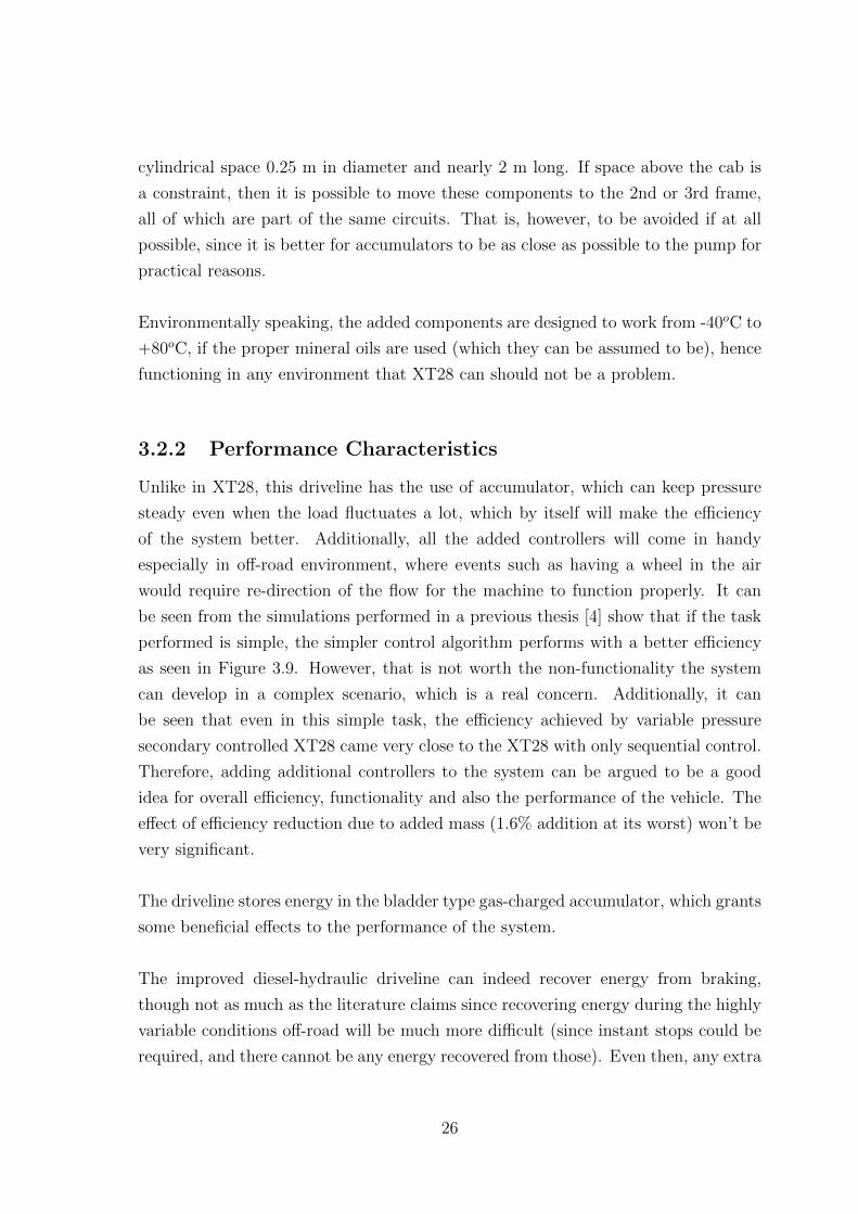
cylindrical space 0.25 m in diameter and nearly 2 m long. If space above the cab is
a constraint, then it is possible to move these components to the 2nd or 3rd frame,
all of which are part of the same circuits. That is, however, to be avoided if at all
possible, since it is better for accumulators to be as close as possible to the pump for
practical reasons.
Environmentally speaking, the added components are designed to work from -40oC to
+80oC, if the proper mineral oils are used (which they can be assumed to be), hence
functioning in any environment that XT28 can should not be a problem.
3.2.2 Performance Characteristics
Unlike in XT28, this driveline has the use of accumulator, which can keep pressure
steady even when the load fluctuates a lot, which by itself will make the efficiency
of the system better. Additionally, all the added controllers will come in handy
especially in off-road environment, where events such as having a wheel in the air
would require re-direction of the flow for the machine to function properly. It can
be seen from the simulations performed in a previous thesis [4] show that if the task
performed is simple, the simpler control algorithm performs with a better efficiency
as seen in Figure 3.9. However, that is not worth the non-functionality the system
can develop in a complex scenario, which is a real concern. Additionally, it can
be seen that even in this simple task, the efficiency achieved by variable pressure
secondary controlled XT28 came very close to the XT28 with only sequential control.
Therefore, adding additional controllers to the system can be argued to be a good
idea for overall efficiency, functionality and also the performance of the vehicle. The
effect of efficiency reduction due to added mass (1.6% addition at its worst) won’t be
very significant.
The driveline stores energy in the bladder type gas-charged accumulator, which grants
some beneficial effects to the performance of the system.
The improved diesel-hydraulic driveline can indeed recover energy from braking,
though not as much as the literature claims since recovering energy during the highly
variable conditions off-road will be much more difficult (since instant stops could be
required, and there cannot be any energy recovered from those). Even then, any extra
26

Figure 3.9: Result of simple simulation for XT28 (unloaded and loaded) involvingdifferent control methods[4]
power that can be returned to the accumulator is an added bonus.
With the additional control employed, this driveline is much easier to control than
XT28 in complicated situations.
This driveline is much better at giving good response to operator direction since it has
the use of velocity feedback and speed control to match the operator requirements.
Although the impedance in the system and the response time will be slightly longer
due to more computations required for better logic.
3.2.3 Practicality Characteristics
From financial perspective, the improved diesel-hydraulic driveline is a bit costlier
than XT28 due to additional components purchased.
The components added to XT28 to make this driveline are standard and therefore
easily accessible. The only problem would be the bi-directional motors required to
make regeneration from braking possible. However since one of the papers advocating
its used is published by the same manufacturer that provides the XT28 its motors
(Bosch Rexroth AG [11]), it should be possible to acquire the necessary motors.
27
Chapter 4
Diesel-Electric Concept
4.1 Concept Definition
4.1.1 Morphological Chart
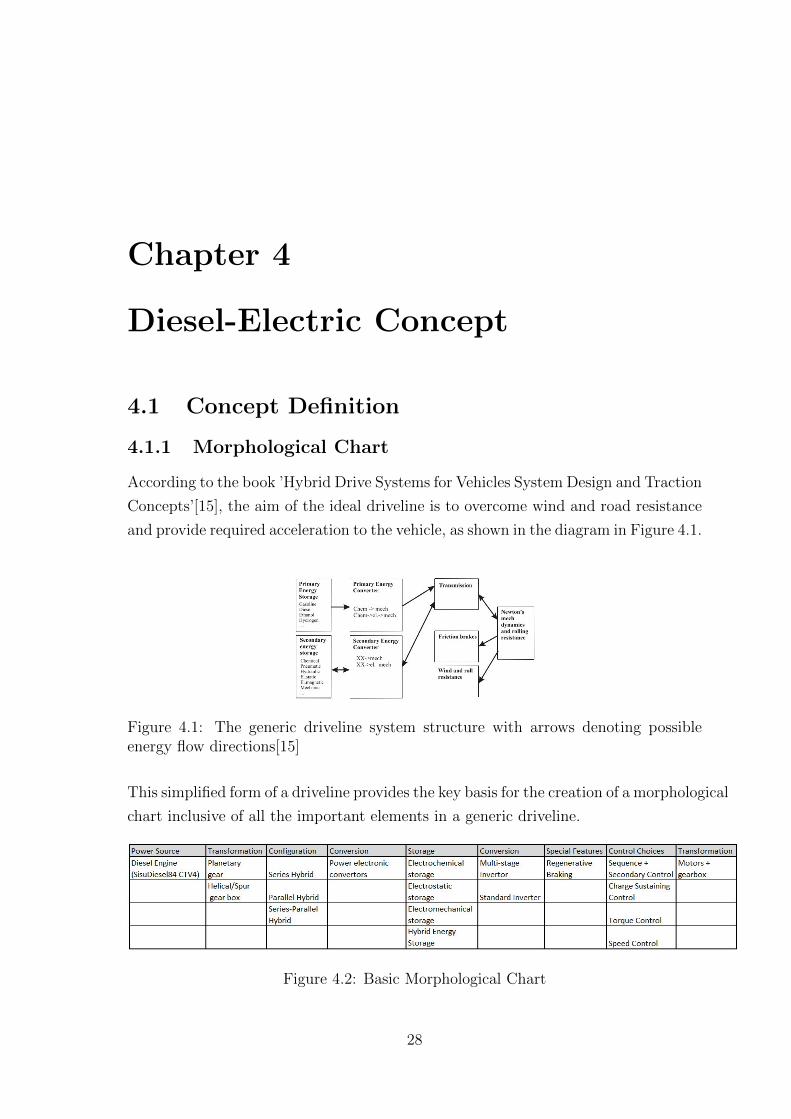
According to the book ’Hybrid Drive Systems for Vehicles System Design and Traction
Concepts’[15], the aim of the ideal driveline is to overcome wind and road resistance
and provide required acceleration to the vehicle, as shown in the diagram in Figure 4.1.
Figure 4.1: The generic driveline system structure with arrows denoting possibleenergy flow directions[15]
This simplified form of a driveline provides the key basis for the creation of a morphological
chart inclusive of all the important elements in a generic driveline.
Figure 4.2: Basic Morphological Chart
28
4.1.2 Possible Architectures
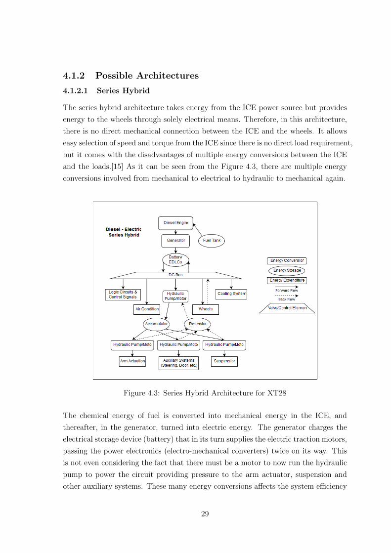
4.1.2.1 Series Hybrid
The series hybrid architecture takes energy from the ICE power source but provides
energy to the wheels through solely electrical means. Therefore, in this architecture,
there is no direct mechanical connection between the ICE and the wheels. It allows
easy selection of speed and torque from the ICE since there is no direct load requirement,
but it comes with the disadvantages of multiple energy conversions between the ICE
and the loads.[15] As it can be seen from the Figure 4.3, there are multiple energy
conversions involved from mechanical to electrical to hydraulic to mechanical again.
Figure 4.3: Series Hybrid Architecture for XT28
The chemical energy of fuel is converted into mechanical energy in the ICE, and
thereafter, in the generator, turned into electric energy. The generator charges the
electrical storage device (battery) that in its turn supplies the electric traction motors,
passing the power electronics (electro-mechanical converters) twice on its way. This
is not even considering the fact that there must be a motor to now run the hydraulic
pump to power the circuit providing pressure to the arm actuator, suspension and
other auxiliary systems. These many energy conversions affects the system efficiency
29

in a negative way. The simplest form of a series hybrid vehicle is an electric vehicle,
equipped with a range extender in the form of an ICE. The XT28, however, is a much
more complex machine.
An important decision when running the series hybrid is to choose between the control
strategies of Charge sustaining or Charge depletion. With Charge sustaining strategy,
the ICE is involved as often as feasible to compensate deviations in battery charge
level, thereby minimizing these deviations. With small deviations in battery energy,
less battery energy is needed and consequently a smaller battery. On the other hand,
in the charge depletion strategy the vehicle is allowed to run in pure electric mode
until the battery SOC (state of charge) hits a minimum limitation when the ICE
is started and used to charge the battery up to a maximum limitation where the
ICE is turned off, and the procedure is started again. In addition to this procedure
requiring a larger energy storage unit, the charge sustaining strategy is much more
advantageous to use in an off-road situation where sudden fluctuations in load are
common.
4.1.2.2 Parallel Hybrid
The parallel hybrid is a combination of two drive systems. The ICE is mechanically
connected to the wheels via a gearbox. The gearbox can be manual, automatic, a
CVT or an automatically controlled manual gearbox. The working point of the hybrid
can be chosen relatively freely with the help of the electrical machines, i.e. the speed
of the ICE is chosen with the gearbox and the torque with the electric machines.
There are three options available: pure electric operation, pure ICE operation and a
combined operation when the electric drive absorbs or delivers power to improve the
ICE operating point. To achieve peak tractive power, both the ICE and the electric
machine are used.
Although this is an attractive option for high performance road cars, it’s impractical
for an off-road machine in comparison to the much better advantages provided by the
Series Hybrid.
4.1.2.3 Series-Parallel Hybrid
Another possible driveline architecture is the Series-Parallel Hybrid, also called as the
Power Split Hybrid (PSH). It can be regarded as a mix between the series and parallel
30

hybrid state. The PSH is even called complex, combined or dual hybrid vehicle. This
is the type of transmission used in Toyota Prius. Unlike the parallel hybrid, which only
is connected to the transmission (in both energy absorption and supply) between ICE
and the differential/gearbox, the PSH is connected also directly to the wheels through
the final gear set, allowing a greater degree of control at the power transmitted to
the wheels. Most of this is achieved through innovative use of Planetary gear systems.
Like the Parallel Hybrid System, even though PSH is an interesting concept, it
holds much more attraction to performance driven road cars compared to heavy duty
vehicles such as the XT28, since the instant power to the wheel at the cost of poor
efficiency is not a priority for its function.
4.1.3 Component Selection
4.1.3.1 Power Source
The power source for the Diesel-Electric Hybrid remains unchanged as the SisuDiesel
Citius 84 CTA-4V, as described in Chapter 2.
4.1.3.2 Power Electronic Converter
Power electronic converter is a term used for devices used for interconversion between
electrical and mechanical energy, or a motor/generator in simple terms. Usually for
a system such as the XT28, a non-standard generator can be ordered.
Secondary energy storages like batteries; super capacitors and fuel cell systems are
usually adapted to a common dc link voltage via a power electronic converter as
shown in Figure 4.4.
Figure 4.4: Converter controlled electrical machine and secondary energy storage,both adapted to a common dc link voltage via power electronic controllers[15]
31

These converters are usually highly efficient, peaking at 97-98%. The losses involved
are mainly commutation losses and conduction losses. The commutation losses occur
when any of the power electronic components are switching, and these components
for a short moment in time operate with a high voltage drop and high current
simultaneously. The conduction losses occur when the converter current flows through
any of the power electronic components that exhibit a voltage in the range of a
few volts[15]. Due to the almost constant nature of the power electronic converter
efficiency it is not a big mistake to represent the converter losses with a fix value,
e.g. 97 % that describes most well designed power electronic converters. The same
applies to motors as well.
4.1.3.3 Energy Transfer
The energy transfer between different electrical devices is done through power and
signal cables. An important factor to remember here is that systems connected to
the same galvanic circuit expose each other to signals transferred via the connecting
conductors. The frequency range is from zero Hertz up, and the connecting conductors
can be both power cables and signal cables, e.g. a communication bus. One example
is the generator in a conventional car, where the diode rectifier is a cause of a voltage
and current ripple that vary in frequency as the speed of the generator varies with the
speed of the ICE. This voltage ripple is transferred via the 12 V system to all loads
connected and may e.g. be heard as a whine in the sound system[15]. Therefore, care
must be taken about the location and bundling of power and signal cables to avoid
interference.
4.1.3.4 Energy Storage Device
In additional to the fuel storage, energy is also stored in form of electricity (chemical/static
forms) using the following devices:
Electrochemical storage:
Electrochemical storage converts an electrical charge into chemical energy by changing
the chemical composition of the charging elements. Figure 4.5 shows different possible
electrochemical energy storage types [15] in relation to each other in terms of energy
density, power density and cycle life.
32
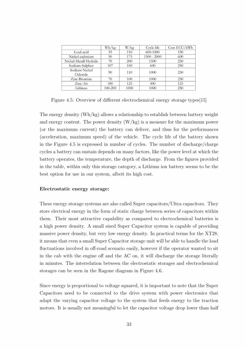
Figure 4.5: Overview of different electrochemical energy storage types[15]
The energy density (Wh/kg) allows a relationship to establish between battery weight
and energy content. The power density (W/kg) is a measure for the maximum power
(or the maximum current) the battery can deliver, and thus for the performances
(acceleration, maximum speed) of the vehicle. The cycle life of the battery shown
in the Figure 4.5 is expressed in number of cycles. The number of discharge/charge
cycles a battery can sustain depends on many factors, like the power level at which the
battery operates, the temperature, the depth of discharge. From the figures provided
in the table, within only this storage category, a Lithium ion battery seems to be the
best option for use in our system, albeit its high cost.
Electrostatic energy storage:
These energy storage systems are also called Super capacitors/Ultra capacitors. They
store electrical energy in the form of static charge between series of capacitors within
them. Their most attractive capability as compared to electrochemical batteries is
a high power density. A small sized Super Capacitor system is capable of providing
massive power density, but very low energy density. In practical terms for the XT28,
it means that even a small Super Capacitor storage unit will be able to handle the load
fluctuations involved in off-road scenario easily, however if the operator wanted to sit
in the cab with the engine off and the AC on, it will discharge the storage literally
in minutes. The interrelation between the electrostatic storages and electrochemical
storages can be seen in the Ragone diagram in Figure 4.6.
Since energy is proportional to voltage squared, it is important to note that the Super
Capacitors need to be connected to the drive system with power electronics that
adapt the varying capacitor voltage to the system that feeds energy to the traction
motors. It is usually not meaningful to let the capacitor voltage drop lower than half
33

Figure 4.6: Ragone diagram (cell level)[16]
its maximum voltage, since only a quarter of the energy is left when the voltage is
halved. In addition, the maximum power is based on the maximum current allowed
in the conductors of the capacitor, which means that if the voltage is reduced to half,
then the maximum power is also reduced to half[15].
Electromechanical storages:
This concept stores energy in mechanical form, through flywheels. It is inadvisable
to use it in vehicles since it is heavy and not ideal as a moving storage.
Hybrid energy storages:
For our application in XT28, the electrochemical storages like Lithium-ion batteries
will need large mass to effectively be able to provide enough power density to be able
to provide for the load fluctuations. On the other hand, Super Capacitor storages
will need a large mass to be able to have enough energy density to provide for basic
functions when the Diesel Engine is not running.
This paradox can be solved through a compact and lightweight energy storage can
be developed by hybridizing ultracapacitors and batteries together, in which the
batteries supply most of the energy density and ultracapacitors supply most of the
power density. To provide a required tractive power of 245kW, the combination of
electrochemical and electrostatic storage to be combined can be found in the table
shown in Figure 4.7.
34

Figure 4.7: Characteristic parameters of Hybrid Energy Storage[17]
Therefore the combination of Li-ion and Super Capacitor Hybrid Storage suits our
needs perfectly. If the energy storage devices in this system are compared to the
accumulators in the hydraulic system from Chapter 3, the electrical drive-lines seems
to have a huge advantage in the storage area.
4.1.3.5 Inverter
If AC motors are used for the wheels, having inverters on board the vehicle is a
necessity. Multilevel inverters are well suited for this application because of the high
VA ratings possible with these inverters and the their capability to meet the high
power demands near 250kW as they are expected to[18]. They are an option to the
standard inverters that are provided with an AC motor by the manufacturer. An
example of Multi-level inverter design is shown in Figure 4.8.
4.1.3.6 Electric Motors
Power requirement of motor:
The engine can provide a maximum of approximately 250kW to the wheels, for worst
case scenario, let us assume that each motor should be able to handle the maximum
power that can be run through it. Additionally, by calculating the maximum power
that a hydraulic motor can achieve (see Appendix A) at maximum displacement
setting is also close to 250kW.
35
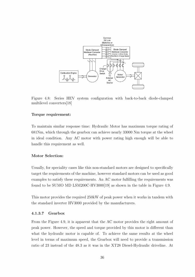
Figure 4.8: Series HEV system configuration with back-to-back diode-clampedmultilevel converters[18]
Torque requirement:
To maintain similar response time: Hydraulic Motor has maximum torque rating of
681Nm, which through the gearbox can achieve nearly 33000 Nm torque at the wheel
in ideal condition. Any AC motor with power rating high enough will be able to
handle this requirement as well.
Motor Selection:
Usually, for speciality cases like this non-standard motors are designed to specifically
target the requirements of the machine, however standard motors can be used as good
examples to satisfy these requirements. An AC motor fulfilling the requirements was
found to be SUMO MD LSM200C-HV3000[19] as shown in the table in Figure 4.9.
This motor provides the required 250kW of peak power when it works in tandem with
the standard inverter HV3000 provided by the manufacturers.
4.1.3.7 Gearbox
From the Figure 4.9, it is apparent that the AC motor provides the right amount of
peak power. However, the speed and torque provided by this motor is different than
what the hydraulic motor is capable of. To achieve the same results at the wheel
level in terms of maximum speed, the Gearbox will need to provide a transmission
ratio of 23 instead of the 48.3 as it was in the XT28 Diesel-Hydraulic driveline. At
36
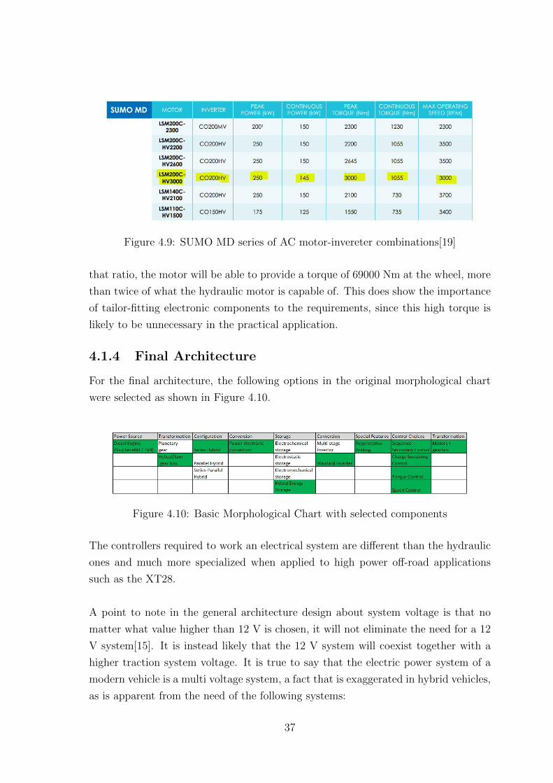
Figure 4.9: SUMO MD series of AC motor-invereter combinations[19]
that ratio, the motor will be able to provide a torque of 69000 Nm at the wheel, more
than twice of what the hydraulic motor is capable of. This does show the importance
of tailor-fitting electronic components to the requirements, since this high torque is
likely to be unnecessary in the practical application.
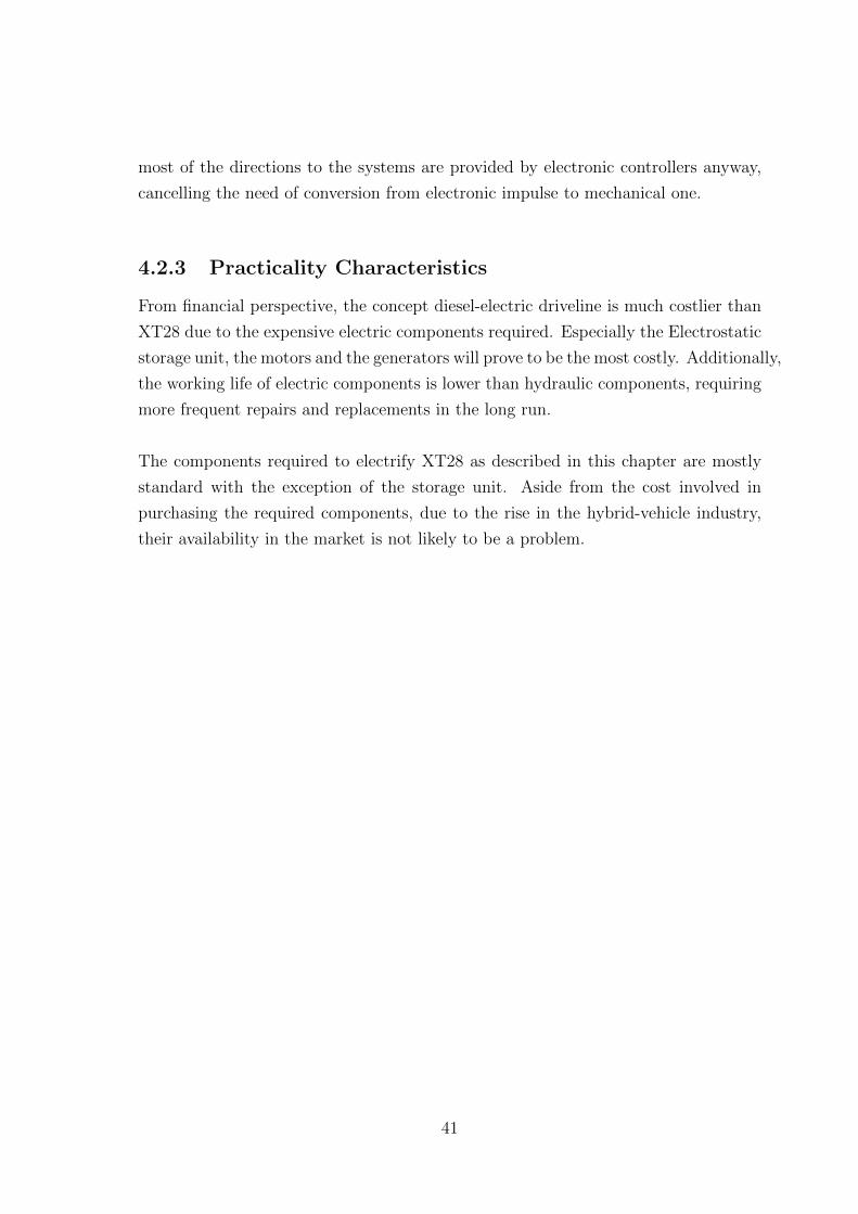
4.1.4 Final Architecture
For the final architecture, the following options in the original morphological chart
were selected as shown in Figure 4.10.
Figure 4.10: Basic Morphological Chart with selected components
The controllers required to work an electrical system are different than the hydraulic
ones and much more specialized when applied to high power off-road applications
such as the XT28.
A point to note in the general architecture design about system voltage is that no
matter what value higher than 12 V is chosen, it will not eliminate the need for a 12
V system[15]. It is instead likely that the 12 V system will coexist together with a
higher traction system voltage. It is true to say that the electric power system of a
modern vehicle is a multi voltage system, a fact that is exaggerated in hybrid vehicles,
as is apparent from the need of the following systems:
37

• 12 Volts is the standard voltage for instrumentation, low power actuators and
low power lighting. The 12 V battery at this voltage level is also called the
service battery.
• 5 Volts is used in the many micro processors in various controllers.
• 100-500 V DC link voltage for the traction system. This voltage level may also
be used for e.g. electric shock absorbers in the wheel suspension system.
• 36 V used in sub systems designed to comply with the 42 Volt standard.
Figure 4.11: Final Architecture of Diesel-Electric Driveline
At least the three first of these voltage levels are a realistic combination, to be
expected in a hybrid electric vehicle. It is not an easy task to design such a multi
voltage system. The main difficulties involved are:
• Power bridges are needed between the different voltage levels, at least between
the 12 V and the traction system voltage. In a hybrid vehicle the traction
battery is charged by means of the hybrid system control, and the 12 V battery
is supplied from the traction battery via a DC/DC-converter.
• Due to the high voltage of the traction battery, there must not be any possibility
for the normal vehicle user to misuse the connections of the electric power
system. Connection of additional equipment like extra headlights, or jumper
start of another vehicle, must be practically impossible to do in other ways than
the right way.
38

• A deformation of the vehicle body in an accident may cut through the isolation
of wires connected to the traction battery. This short circuit may not cause a
hazardous situation, e.g. fire.
Therefore, the final architecture for this concept should look as shown in the Figure
4.11.
4.2 Analysis of Diesel-Electric Concept
To summarize the Diesel-Electric Concept driveline in terms of characteristics described
in the methodology:
4.2.1 Physical Characteristics
The Diesel-Electric Concept driveline is, as projected, is the highest of the three
drivelines from the perspective of mass. However, surprisingly, the difference between
the improved diesel-hydraulic driveline and this driveline is very small. This is likely
due to the fact that the cumulative weight of all the hydraulic components put
together offsets the singularly large electric motors and generators. The mass of
possible component list is shown in Figure 4.12. Adding the weight to the total,
the driveline now weighs 20.5% - 36.3%, which is a much small fraction added than
expected. The total mass increase from unloaded XT28 is 5.7% which is very small.
For detailed analysis of the masses of all the concepts, please refer to Appendix B.
The sizes of electric components replacing the hydraulic ones are fairly large. The
biggest factor of concern was the motor, which according to the dimensions provided,
has a diameter of 452 mm. This is still small as compared to the total rim diameter of
775 mm according to the Specs-sheet The dimensions of generator and batteries are
not known, but as they replace the numerous pumps and other hydraulic equipment,
space should not be a concern.
Environmentally speaking, there should be no problems for the hybrid electric driveline
to work in Swedish forests if the Hydraulic driveline managed to avoid them. Only
additional concern could be the heat generated by motors and inverters on summer
days. To compensate for that, additional cooling packages are included in the design
as seen in the table in Figure 4.12.
39

Figure 4.12: Component weights and their distribution in Diesel-Electric Conceptdriveline
4.2.2 Performance Characteristics
There is no doubt that a diesel-electric driveline will have higher operating efficiency
than any diesel-hydraulic driveline. The efficiency curve for Power electronic converters
(Generators and motors) are usually consistently flat between 95%-98% and any
losses happening during energy conversions will still be lower than the potential
losses incurred by operation of the diesel-hydraulic driveline. The additional boost in
efficiency easily compensates for the near 5% increase in mass of the unloaded vehicle.
If we assume the vehicle is loaded, the benefits are even greater.
The driveline stores energy in the hybrid energy storage of electrochemical and
electrostatic components. It provides a high power and high energy density storage,
perfect for the off-road load requirements.
The improved diesel-hydraulic driveline can indeed recover energy from braking,
though not as much as the literature claims since recovering energy during the highly
variable conditions off-road will be much more difficult (since instant stops could be
required, and there cannot be any energy recovered from those). Even then, any extra
power that can be returned to the accumulator is an added bonus.
Generally electrical components are easier to control and get fast response from since
40
most of the directions to the systems are provided by electronic controllers anyway,
cancelling the need of conversion from electronic impulse to mechanical one.
4.2.3 Practicality Characteristics
From financial perspective, the concept diesel-electric driveline is much costlier than
XT28 due to the expensive electric components required. Especially the Electrostatic
storage unit, the motors and the generators will prove to be the most costly. Additionally,
the working life of electric components is lower than hydraulic components, requiring
more frequent repairs and replacements in the long run.
The components required to electrify XT28 as described in this chapter are mostly
standard with the exception of the storage unit. Aside from the cost involved in
purchasing the required components, due to the rise in the hybrid-vehicle industry,
their availability in the market is not likely to be a problem.
41
Chapter 5
Concept comparison and discussion
5.1 Comparison Method
As the concepts of drivelines are developed in the previous chapter and are described
in detail, the next step is to compare between them. Since the concepts are developed
on the base concepts of the driveline in XT28, using Pugh Matrix as a method of
comparison may be a good idea.
This method consists of comparing one or more concepts against a base-line concept
in terms of key criteria of comparison. If the competitor concept is better than the
base-line concept, it scores a positive point. If it is worse, it scores a negative point.
If they are effectively the same, then it scores a zero for that criterion. After relative
performance of each concept against each of the criteria is recorded, the resulting
points are added together for each concept, and comparing them to each other will
tell which one of the concepts was the winner.
5.1.1 Weighted-Pugh Matrix Selection
The Pugh Matrix method of comparison has following two key weaknesses:
• It does not assign any way to understand the relative importance between
different criteria of comparison
• When one concept is better than another, there is no provision to specify the
degree of difference between the concepts
42
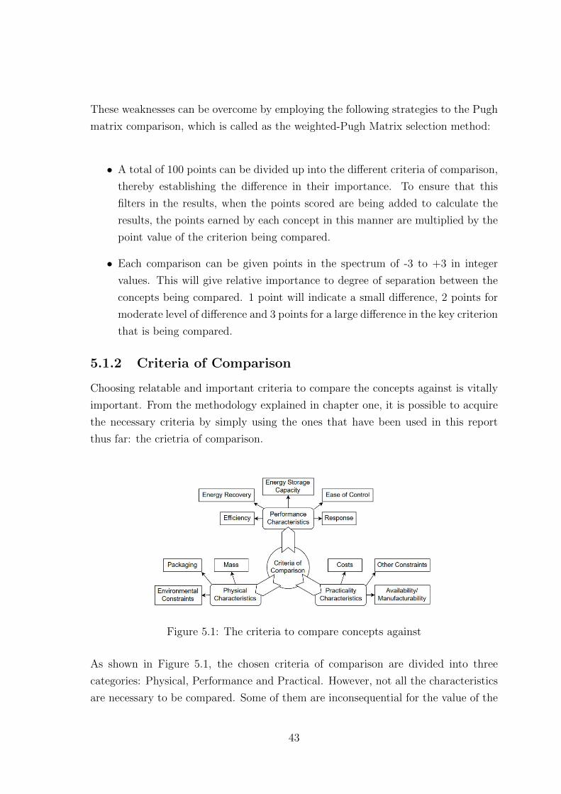
These weaknesses can be overcome by employing the following strategies to the Pugh
matrix comparison, which is called as the weighted-Pugh Matrix selection method:
• A total of 100 points can be divided up into the different criteria of comparison,
thereby establishing the difference in their importance. To ensure that this
filters in the results, when the points scored are being added to calculate the
results, the points earned by each concept in this manner are multiplied by the
point value of the criterion being compared.
• Each comparison can be given points in the spectrum of -3 to +3 in integer
values. This will give relative importance to degree of separation between the
concepts being compared. 1 point will indicate a small difference, 2 points for
moderate level of difference and 3 points for a large difference in the key criterion
that is being compared.
5.1.2 Criteria of Comparison
Choosing relatable and important criteria to compare the concepts against is vitally
important. From the methodology explained in chapter one, it is possible to acquire
the necessary criteria by simply using the ones that have been used in this report
thus far: the crietria of comparison.
Figure 5.1: The criteria to compare concepts against
As shown in Figure 5.1, the chosen criteria of comparison are divided into three
categories: Physical, Performance and Practical. However, not all the characteristics
are necessary to be compared. Some of them are inconsequential for the value of the
43
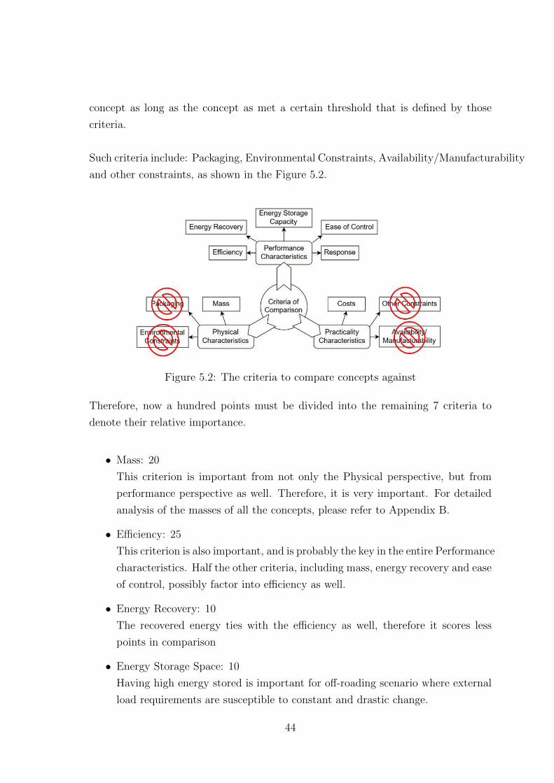
concept as long as the concept as met a certain threshold that is defined by those
criteria.
Such criteria include: Packaging, Environmental Constraints, Availability/Manufacturability
and other constraints, as shown in the Figure 5.2.
Figure 5.2: The criteria to compare concepts against
Therefore, now a hundred points must be divided into the remaining 7 criteria to
denote their relative importance.
• Mass: 20
This criterion is important from not only the Physical perspective, but from
performance perspective as well. Therefore, it is very important. For detailed
analysis of the masses of all the concepts, please refer to Appendix B.
• Efficiency: 25
This criterion is also important, and is probably the key in the entire Performance
characteristics. Half the other criteria, including mass, energy recovery and ease
of control, possibly factor into efficiency as well.
• Energy Recovery: 10
The recovered energy ties with the efficiency as well, therefore it scores less
points in comparison
• Energy Storage Space: 10
Having high energy stored is important for off-roading scenario where external
load requirements are susceptible to constant and drastic change.
44
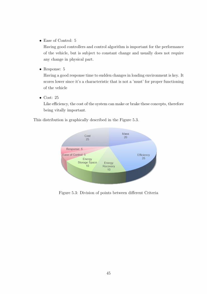
• Ease of Control: 5
Having good controllers and control algorithm is important for the performance
of the vehicle, but is subject to constant change and usually does not require
any change in physical part.
• Response: 5
Having a good response time to sudden changes in loading environment is key. It
scores lower since it’s a characteristic that is not a ’must’ for proper functioning
of the vehicle
• Cost: 25
Like efficiency, the cost of the system can make or brake these concepts, therefore
being vitally important.
This distribution is graphically described in the Figure 5.3.
Figure 5.3: Division of points between different Criteria
45
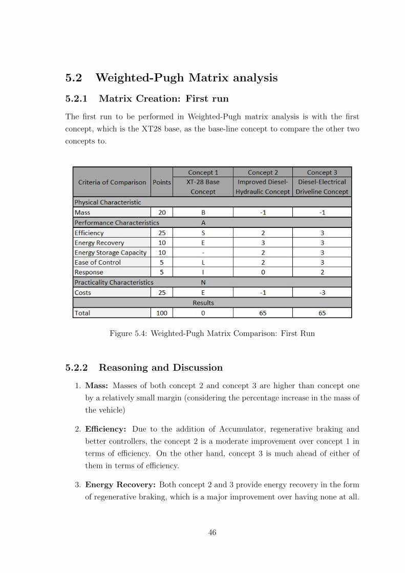
5.2 Weighted-Pugh Matrix analysis
5.2.1 Matrix Creation: First run
The first run to be performed in Weighted-Pugh matrix analysis is with the first
concept, which is the XT28 base, as the base-line concept to compare the other two
concepts to.
Figure 5.4: Weighted-Pugh Matrix Comparison: First Run
5.2.2 Reasoning and Discussion
1. Mass: Masses of both concept 2 and concept 3 are higher than concept one
by a relatively small margin (considering the percentage increase in the mass of
the vehicle)
2. Efficiency: Due to the addition of Accumulator, regenerative braking and
better controllers, the concept 2 is a moderate improvement over concept 1 in
terms of efficiency. On the other hand, concept 3 is much ahead of either of
them in terms of efficiency.
3. Energy Recovery: Both concept 2 and 3 provide energy recovery in the form
of regenerative braking, which is a major improvement over having none at all.
46

4. Energy Storage Capacity: Unlike concept 1, concept 2 has accumulator to
store energy in in case of load fluctuations which is a moderate improvement
over only having pressure in hydraulic circuit as a backup. Unlike either of
them, concept 3 has a full storage designed to last longer due to auxiliary
requirements, which results in it being even better than concept 2.
5. Ease of Control: With better controllers concept 2 is a significant improvement
over concept 1, but still cannot compare to the ease with which any electronic
system can be controlled, as it is in concept 3.
6. Response: Since both concepts 1 and 2 use hydraulic driveline, the possible
response time due to component and control characteristics is about the same.
Concept 3 scores high in the criterion as electric systems hold moderate advantage
over other system in getting quick response in rotary systems.
7. Cost: Concept 2 is slightly more expensive as compared to concept 1 due
to using a few additional components. Concept 3, having several expensive
electrical components in the purchase list, scores the lowest.
From these observations, the result of this comparison is a tie between concepts 2 and
3.
5.2.3 Matrix Creation: Confirmation run
Irrespective of the tie that took place in the first run of Weighted-Pugh matrix
comparison, an additional confirmation run of comparisons must be run. This is
due to the fact that, even if we declare one of the concepts as a winner in the first
run, the score between the two concepts which were not compared between each other
are not guaranteed to have the same inter-relationship as shown by the first run scores
if the baseline changes. Therefore, the confirmation run is performed with the winner
of the First run as the baseline. When the baseline is changed, the perspective behind
the comparison changes, which may cause major change in the scores.
In our case, a Confirmation run comparison is performed with concept 3 as the
base-line, as shown in Figure 5.5.
47

Figure 5.5: Weighted-Pugh Matrix Comparison: Confirmation Run
5.2.4 Reasoning and Discussion
1. Mass: Both concepts 1 and 2 are a slight improvement over concept 3 in the
mass department.
2. Efficiency: Concept 1 is much inferior in efficiency as compared to concept
3. Concept 2 fares better since it has energy recovery as an option with better
controllers.
3. Energy Recovery: As concept 1 has no energy recovery system in place, it
scores the lowest. Even though concept 2 has energy recovery system available,
it comes with practical problems and has slower reaction speed due to the flow
being required to change direction within the motor/pump. Therefore it scores
as being moderately worse than the electronic energy recovery system.
4. Energy Storage Capacity: Concept 1 has no energy storage to speak of,
therefore it scores the lowest points. With the existence of accumulator, the
concept 3 is only a little behind concept 3, and therefore scores a -1.
5. Ease of Control: Due to its basic controllers, concept 1 scores the lowest in
this criterion as well. Despite having numerous controllers, concept 2 cannot
overcome the difference between hydraulic and electronic systems, which provide
the versatility to concept to hold a significant advantage over concept 2.
48
6. Response: Being hydraulic concepts, both concepts 1 and 2 have a significant
disadvantage to electronic concept 3 in terms of quick response.
7. Cost: Concept 3 has a major disadvantage in terms of cost compared to either
of concepts 1 or 2.
From these observations, the result of this comparison is a minor win for the concept
3: Diesel-Electric Driveline concept and over concept 2: Improved Diesel-Hydraulic
Concept.
5.2.5 Results of Comparison
As it can be seen from the comparisons, the Diesel-Electric Driveline concept holds a
slight edge over the Improved Diesel-Hydraulic Concept. Even though the 3rd concept
scores major points against the other two concepts in the Performance Characteristics,
it suffers a major drawback in terms of high cost, which allows the 2nd concept to be
a close second in this comparison.
49
Chapter 6
Conclusion
6.1 Conclusion
From the work performed in this thesis, following conclusions can be drawn:
1. The electrification of the XT28 is a definite possibility for the future. There
are no practical or physical constraints holding it back, and it even holds
a small edge over any improvements that can be performed on the current
Diesel-Hydraulic series hybrid set-up.
2. The main advantage electrification concept holds over the Diesel-Hydraulic
driveline is the efficiency. Unlike what was initially thought, the mass difference
between the two is not very significant. In addition to that, the inherent
advantages held by electronic hybrid over hydraulic hybrid gives the electrification
concept a significant advantage.
3. However, this conjuncture of efficiency advantage cannot be proved without
either manufacturing a prototype of the driveline or comparing detailed simulations
of both the concepts against each other. Even after this, the results will still not
be fully conclusive due to the major effect controllers have on the performance
of the vehicle. Only if both concepts are given professional level controllers to
remove any inadvertent advantage can there be an objective comparison.
4. A major disadvantage of electrification concept is the high cost involved for
the individual components. However, as the technology behind hybrid vehicle
advances, it is likely that the costs for these components will come down in the
future, making this option more and more attractive.
50
6.2 Future Work
1. In depth cost analysis will help understand the actual difference in cost for
Hydraulic and Electric Drivelines. This, however, is a tricky task since usually
getting realistic quotes from manufacturers for components without bulk orders
is difficult.
2. Detailed realistic modelling of both Hydraulic and Electric Drivelines and their
controllers could give a rough idea about how the relative efficiencies stack up
against each other.
3. Manufactured prototype of at least the Diesel-Electric driveline will give even
more conclusive results about validity of the powertrain and open ways for more
practical real-world tests.
51
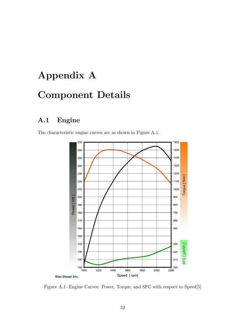
Appendix A
Component Details
A.1 Engine
The characteristic engine curves are as shown in Figure A.1.
Figure A.1: Engine Curves: Power, Torque, and SFC with respect to Speed[5]
52

The other important technical data is as follows:
1. Displacement: 8.4 L
2. Number of Cylinders: 6 In-Line
3. Rated Power: 246kW/2200 RPM, (ISO14396 gross)
4. Maximum Power: 265kW/2000 RPM
5. Maximum Torque: 1500Nm/1300-1500 RPM
6. Idling Speed: 600-1100 RPM
7. Maximum Speed: 2350 RPM
8. Engine Management: SisuTronic EEM3 with Bosch EDC7
A.2 Pump and Motors
A.2.1 Pump
The XT28 uses special sized A4VG 140/32 variable displacement pumps made by
Bosch Rexroth AG. These pumps have minimum-maximum displacement of 28.3 to
140.44 cm3/rev respectively. The maximum power transmissible through this pump is
257 kW at nominal pressure difference of 400 bar. At the maximum displacement and
pressure, the pump can reach 2700 RPM. At half corner power, the pump can reach
3000 RPM, and the high idling speed at low pressures is 3100 RPM. Maximum torque
transmissible is 891 Nm. Minimum/Stall speed is 500 RPM. Each pump weighs about
82 kg[8].
The calculated and measured comparisons of hydro-mechanical and volumetric efficiencies
are shown in Figures A.2 and A.3.These graphs are in 3-D surfaces for measurements
performed at specific speeds relative to the maximum speed of pump[4].
A.2.2 Motor
The XT28 uses A6VM 107/63 variable displacement motors made by Bosch Rexroth
AG at each wheel. These motors have minimum-maximum displacement of 0 to 107
cm3/rev respectively. The maximum power transmissible through this pump is 250
kW at nominal pressure difference of 400 bar. At the maximum displacement and
53

Figure A.2: Hydro-mechanical Efficiency of hydraulic pumps as calculated (redsurface) and measured (blue surface)[4]
Figure A.3: Volumetric Efficiency of hydraulic pumps as calculated (red surface) andmeasured (blue surface)[4]
pressure, the pump can reach 3550 RPM. The high idling speed at low displacements
is 6300 RPM. Maximum torque transmissible is 681 Nm[9].
The calculated and measured comparisons of hydro-mechanical and volumetric efficiencies
are shown in Figures A.4 and A.5.These graphs are in 3-D surfaces for measurements
performed at specific speeds relative to the maximum speed of motor[4].
54
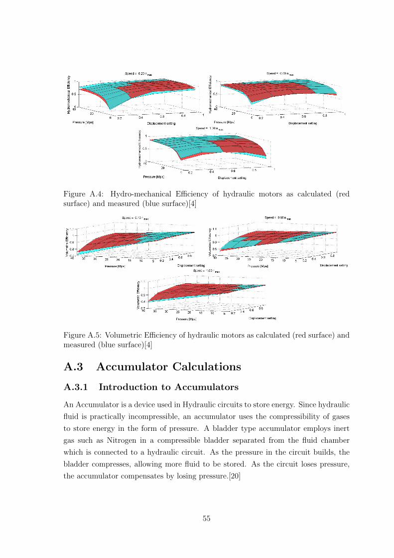
Figure A.4: Hydro-mechanical Efficiency of hydraulic motors as calculated (redsurface) and measured (blue surface)[4]
Figure A.5: Volumetric Efficiency of hydraulic motors as calculated (red surface) andmeasured (blue surface)[4]
A.3 Accumulator Calculations
A.3.1 Introduction to Accumulators
An Accumulator is a device used in Hydraulic circuits to store energy. Since hydraulic
fluid is practically incompressible, an accumulator uses the compressibility of gases
to store energy in the form of pressure. A bladder type accumulator employs inert
gas such as Nitrogen in a compressible bladder separated from the fluid chamber
which is connected to a hydraulic circuit. As the pressure in the circuit builds, the
bladder compresses, allowing more fluid to be stored. As the circuit loses pressure,
the accumulator compensates by losing pressure.[20]
55

A.3.2 Nomenclature
The following symbols are used for mathematical expressions for calculations pertaining
to the functioning of an accumulator.
• P0 = Pre-charge pressure of gas at room temperature with the fluid chamber
fully drained
• P1 = Minimum operating pressure of the hydraulic circuit to be connected to
this accumulator
• P2 = Maximum operating pressure of the hydraulic circuit for safe use of this
accumulator
• KA = Adiabatic Correction Factor
• V0 = Effective gas volume at room conditions
• V2 = Minimum working volume
• V1 = Maximum working volume
• ∆Vth = Theoretical change in working volume due to compression = V1 - V2
• ∆Vact = Actual change in working volume due to compression
A.3.3 Relevant Formulae and Calculations
According to empirical data, the safe pressure variance for bladder-type accumulators[7]
is:
P2 ≤ 4 × P0 (A.1)
Also, the slight variation of safety margin between pre-charge pressure and the minimum
operating pressure can be shown as:
P0 ≈ 0.9 × P1 (A.2)
Considering that the pre-estimated maximum normal pressure for our system is 400
bar, the value of P2 can be considered fixed. Therefore, pre-charged pressure, P0 is
limited to 100 bar as the lowest allowable value, with minimum operating pressure
being approximately 111 bar. However, considering that it can be a safety concern,
this value can be rounded up to 120 bar.
56
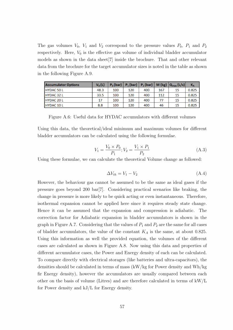
The gas volumes V0, V1 and V2 correspond to the pressure values P0, P1 and P2
respectively. Here, V0 is the effective gas volume of individual bladder accumulator
models as shown in the data sheet[7] inside the brochure. That and other relevant
data from the brochure for the target accumulator sizes is noted in the table as shown
in the following Figure A.9.
Figure A.6: Useful data for HYDAC accumulators with different volumes
Using this data, the theoretical/ideal minimum and maximum volumes for different
bladder accumulators can be calculated using the following formulae.
V1 =V0 × P0
P1
;V2 =V1 × P1
P2
(A.3)
Using these formulae, we can calculate the theoretical Volume change as followed:
∆Vth = V1 − V2 (A.4)
However, the behaviour gas cannot be assumed to be the same as ideal gases if the
pressure goes beyond 200 bar[7]. Considering practical scenarios like braking, the
change in pressure is more likely to be quick acting or even instantaneous. Therefore,
isothermal expansion cannot be applied here since it requires steady state change.
Hence it can be assumed that the expansion and compression is adiabatic. The
correction factor for Adiabatic expansion in bladder accumulators is shown in the
graph in Figure A.7. Considering that the values of P1 and P2 are the same for all cases
of bladder accumulators, the value of the constant KA is the same, at about 0.825.
Using this information as well the provided equation, the volumes of the different
cases are calculated as shown in Figure A.8. Now using this data and properties of
different accumulator cases, the Power and Energy density of each can be calculated.
To compare directly with electrical storages (like batteries and ultra-capacitors), the
densities should be calculated in terms of mass (kW/kg for Power density and Wh/kg
fir Energy density), however the accumulators are usually compared between each
other on the basis of volume (Litres) and are therefore calculated in terms of kW/L
for Power density and kJ/L for Energy density.
57

Figure A.7: Adiabatic expansion in Bladder accumulator [7]
Figure A.8: Comparison of HYDAC accumulators with different volumes
In terms of mass, the Energy and Power Densities are calculated as:
PD =P2 ×Qmax
M;ED =
P2 × ∆Vact
M(A.5)
In terms of volume, the Energy and Power Densities are calculated as:
PD =P2 ×Qmax
V1
;ED =P2 × ∆Vact
V1
(A.6)
Using these formulae and the calculated and measured parameters about different
models of bladder accumulators, Energy and Power densities are calculated as shown
in Table in Figure A.9. It can be observed that Power Density has a predictable
inverse relation to Volume. Energy Density, however, is not so predictable. The value
in terms of volume is constant irrespective of the model since the ratio ∆Vact
V1is the
same for all models. For the Energy Density in terms of mass, the 20L and 10L
accumulators are very low, but the 50L and 32L have very close results, with 32L
accumulator leading with a slight advantage. It was found after trial and error that
58

Figure A.9: Comparison of HYDAC accumulators with different volumes
this result was very dependent on the pressure values, but irrespective of change in
P1 pressure values, the 32L accumulator keeps its lead. Therefore, that should be the
accumulator chosen to be used for this application.
59

Appendix B
Mass distribution
B.1 XT28 Mass distribution
The XT28 mass distribution among its components and systems is well recorded. The
Figure B.1 shows the table of all critical and measured components, their quantities,
the weight per quantity (which may be number, length, or volume), the total mass
for that component and its distribution amongst the three frames. This data is
approximated and some entries made in component category are systems/sub-systems
grouped together for ease of reference. It is to be noted that this data is for the
unloaded forwarder only. The weight of the load to be added in the carrier is not
considered. Therefore the impact of any increase in the driveline weight is shown to
its maximum degree.
However, for the function of this project, keeping track of all these components is not
necessary. It is easier to focus on the components which actually contribute to and
are directly involved in the drive-line structure and would require to be changed in
case of change in drive-line concept. Therefore, for XT28, the components selected
for consideration are shown in Figure B.2. Again, this is only used for estimation and
therefore the values used are not expected to be very accurate. This is used to get a
general idea about mass distribution in the vehicle body.
B.2 Improved XT28 mass distribution
The XT28 and improved version of XT28 as described in chapters 2 and 3 respectively,
are fundamentally the same drivelines. The improved version has a few more functionalities,
and therefore, a few more components added to its component lists. As it can be seen
in Figure B.3 Accumulators, Reservoirs and Additional Control electronics are added.
60

Component Q Kg/Q Weight Front Middle BackFrame (Front) 1 1500.00 1,500 1500 0 0Frame (Middle) 1 1500.00 1,500 0 1500 0Frame (Back 1 800.00 800 0 0 800Pendulam Arms 6 250.00 1,500 500 500 500Bearings 24 0.50 12 4 4 4Engine 1 660.00 660 660 0 0Silencer 1 50.00 50 50 0 0Cooling Package 1 80.00 80 80 0 0AC comp. generator 1 50.00 50 50 0 0Pump-Gearbox 1 100.00 100 100 0 0Tanks 2 15.00 30 30 0 0Pumps Transmission 3 60.00 180 180 0 0Pump implement 1 90.00 90 90 0 0Hydraulic Block 4 15.00 60 60 0 0Wheel Motors 6 200.00 1,200 400 400 400Crane 1 2000.00 2,000 0 2000 0Crane Valves 1 200.00 200 0 200 0P-Arm control valve 1 60.00 60 60 0 0Hydraulic cylinders 11 50.00 550 250 200 100Pins 24 0.50 12 6 4 2Load carrier 1 1000.00 1,000 0 500 500Hoods 1 50.00 50 50 0 0Wheels on rims 6 350.00 2,100 700 700 700Hydraulic Pipes 200 2.00 400 200 120 80Bolt and Screw 300 1.00 300 150 100 50Batteries 2 30.00 60 60 0 0Power Cables 100 0.10 10 5 3 2Cab (ROPS) 1 1500.00 1,500 1500 0 0Cabin tilt 1 100.00 100 100 0 0Steering system 1 10.00 10 10 0 0Xenon lights 14 2.00 28 28 0 0Chair 1 100.00 100 100 0 0AC 1 25 25 25 0 0Fuel 300 0.85 255 255 0 0Filter and house 5 10.00 50 50 0 0Oils 200 0.85 170 170 0 0Paint 10 1.00 10 5 3 2Total Weight: 16,802 7,428 6,234 3,140
Figure B.1: Weight of key components in XT28, with quantity and frame-wisedistribution
61
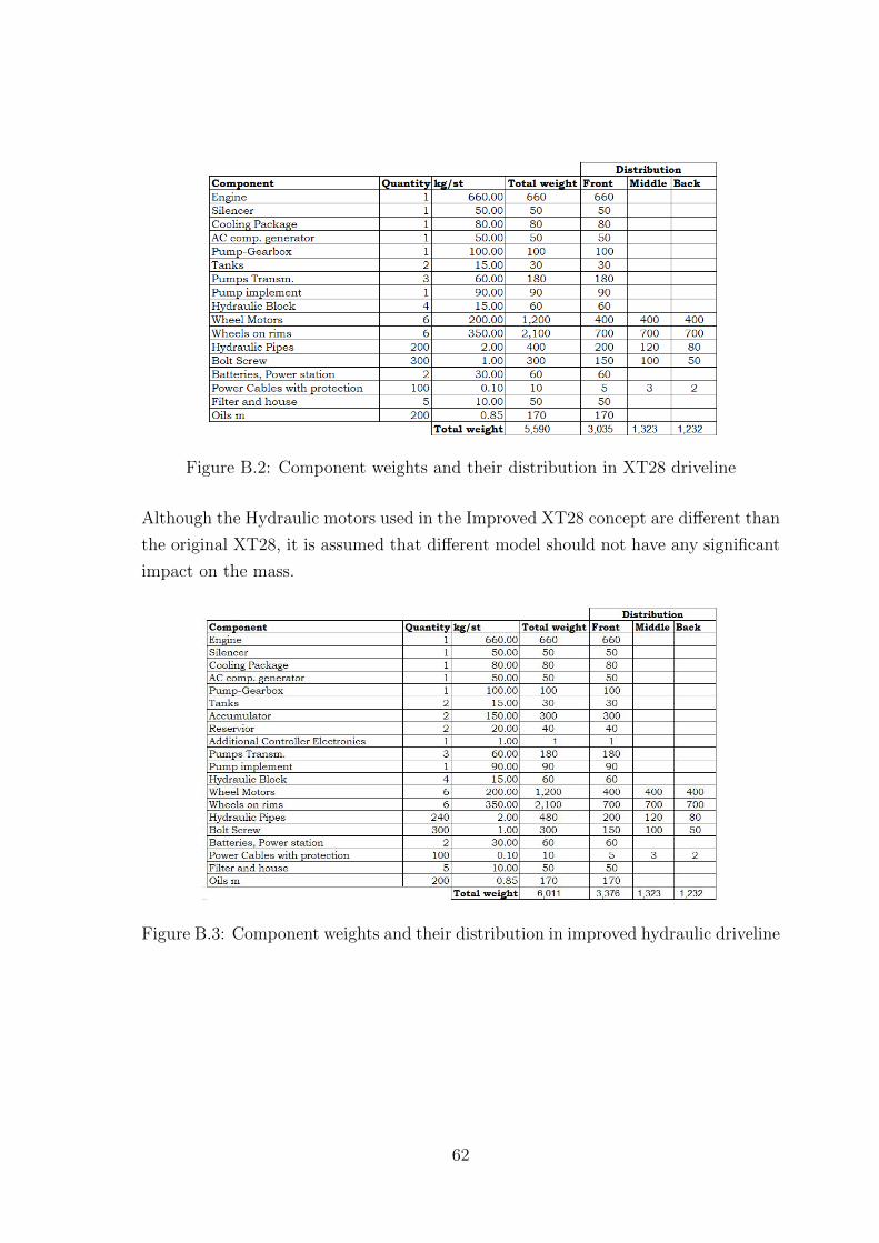
Figure B.2: Component weights and their distribution in XT28 driveline
Although the Hydraulic motors used in the Improved XT28 concept are different than
the original XT28, it is assumed that different model should not have any significant
impact on the mass.
Figure B.3: Component weights and their distribution in improved hydraulic driveline
62

B.3 Diesel-Electric Driveline mass distribution
The Diesel-Electric driveline concept is a lot different than either the original or the
improved XT28 Diesel-Hydraulic ones. The full list of driveline components and their
mass distribution is seen in Figure B.4.
Of course, it isn’t possible to remove all the hydraulic components from the component
list, since it is required to run both the suspension and the crane-arm. However, from
the original list, it is possible to remove the accumulators and reservoirs as well as
reduce the quantity of all hydraulic components so that they are sufficient to run the
remaining loop for suspension and crane-arm.
The pump-gearbox is to be replaced with generator-gearbox, which is assumed to be
heavier since it will require to handle most of the power from the engine (unlike the
pump gearbox, which splits it into two requires less strength). The wheel motors and
their gearboxes are replaced by electric motors and their own gearboxes.
Electric components such as inverters, extra batteries and power power cables are
added to the list or increased in amount.
Figure B.4: Component weights and their distribution in Diesel-Electric Conceptdriveline
63
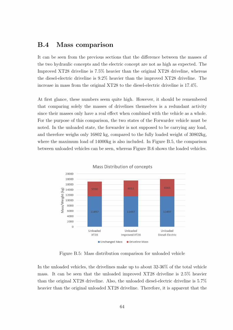
B.4 Mass comparison
It can be seen from the previous sections that the difference between the masses of
the two hydraulic concepts and the electric concept are not as high as expected. The
Improved XT28 driveline is 7.5% heavier than the original XT28 driveline, whereas
the diesel-electric driveline is 9.2% heavier than the improved XT28 driveline. The
increase in mass from the original XT28 to the diesel-electric driveline is 17.4%.
At first glance, these numbers seem quite high. However, it should be remembered
that comparing solely the masses of drivelines themselves is a redundant activity
since their masses only have a real effect when combined with the vehicle as a whole.
For the purpose of this comparison, the two states of the Forwarder vehicle must be
noted. In the unloaded state, the forwarder is not supposed to be carrying any load,
and therefore weighs only 16802 kg, compared to the fully loaded weight of 30802kg,
where the maximum load of 14000kg is also included. In Figure B.5, the comparison
between unloaded vehicles can be seen, whereas Figure B.6 shows the loaded vehicles.
Figure B.5: Mass distribution comparison for unloaded vehicle
In the unloaded vehicles, the drivelines make up to about 32-36% of the total vehicle
mass. It can be seen that the unloaded improved XT28 driveline is 2.5% heavier
than the original XT28 driveline. Also, the unloaded diesel-electric driveline is 5.7%
heavier than the original unloaded XT28 driveline. Therefore, it is apparent that the
64

Figure B.6: Mass distribution comparison for loaded vehicle
increase in the driveline mass is not very significant even in the unloaded state.
In the loaded state, the effect of mass increase in the drivelines is even more muted.
The loaded improved XT28 driveline is 1.4% heavier than the original XT28 driveline
and the loaded diesel-electric driveline is only 3.1% heavier than the original loaded
XT28 driveline. Therefore, the mass increase should not cause any significant reduction
in vehicle efficiency.
65
Bibliography
[1] Skogs Industrierna. Sweden’s Forest Industry in brief - Facts and
Figures, 2016. URL http://www.forestindustries.se/forest-industry/
facts-and-figures/.
[2] Federico Baez. Multi-objective optimization and performance evaluation of active,
semi-active and passive suspensions for forestry machines. PhD thesis, KTH,
2014.
[3] Liselott Ericson, Fredrik Henriksen, and Petter Krus. Modelling and
experimental verification of a secondary controlled six-wheel pendulum arm
forwarder. In 13th ISTVS European Conference, volume 4405, pages 1–10, Rome,
2015.
[4] Johan Fredrik Henriksen. Modeling and control of a hydraulic driveline with
secondary control. PhD thesis, Linkoping University, 2014.
[5] SisuDiesel. SisuDiesel Citius 84 CTA-4V Industrial Engine. Technical report,
Sisu Diesel Inc.
[6] THELL; Rexorth Bosch Group. FADI PAMP. Technical report, Skogforsk, 2013.
[7] Bosch Rexroth AG. Rexroth Accumulators Catalog. http://www.hasmak.
com.tr/rexroth/akumulator/RexrothUSAccumulatorCatalog.pdf, 2015.
Accessed: 2017-06-07.
[8] Bosch Rexroth AG. Axial Piston Variable Pump A4VG Series 32 Data Sheet
[RE 92003/06.12]. Technical report, 2015. URL www.boschrexroth.com/
axial-piston-pumps.
[9] Bosch Rexroth AG. Axial Piston Variable Displacement Motor A6VM Data
Sheet [RE 91604/07.09]. Technical report, Rexroth Bosch Group, 2015. URL
www.boschrexroth.com/axial-piston-motors.
66
[10] Young Jae Kim and Zoran Filipi. Simulation Study of a Series Hydraulic Hybrid
Propulsion System for a Light Truck. SAE Paper 2007-01-4151, (724):776–790,
2007. ISSN 0148-7191. doi: 10.4271/2007-01-4151.
[11] Simon Baseley, Christine Ehret, Edward Greif, and Markus G Kliffken. Hydraulic
Hybrid Systems for Commercial Vehicles Simon. SAE International, (724), 2007.
[12] Bapi Surampudi, Ashok Nedungadi, Gregory Ostrowski, Alan Montemayor, and
Heather Gruenewald. Design and Control Considerations for a Series Heavy Duty
Hybrid Hydraulic Vehicle. SAE Technical Paper, 4970(No. 2009-01-2717), 2009.
doi: 10.4271/2009-01-2717.
[13] A Pourmovahed, N H Beachley, and F J Fronczak. Modeling of a Hydraulic
Energy Regeneration System- Part I : Analytical Treatment. 114(March 1992):
155–159, 1992.
[14] Bin Wu, Chan-Chiao Lin, Zoran Filipi, Huei Peng, and Dennis Assanis.
Optimal Power Management for a Hydraulic Hybrid Delivery Truck. Vehicle
System Dynamics, 42(734):23–40, 2004. ISSN 0042-3114. doi: 10.1080/
00423110412331291562.
[15] Mats Alakula. Hybrid Drive Systems for Vehicles System Design and Traction
Concepts. Lunds Tekniska Hogskola, Lund, 1st edition, 2006.
[16] Omar Hegazy, Ricardo Barrero, Peter Van den Bossche, Mohamed El Baghdadi,
Jelle Smekens, Joeri Van Mierlo, Wouter Vriens, and Bruno Bogaerts. Modeling,
analysis and feasibility study of new drivetrain architectures for off-highway
vehicles. Energy, 109:1056–1074, 2016. ISSN 03605442. doi: 10.1016/j.energy.
2016.05.001. URL http://dx.doi.org/10.1016/j.energy.2016.05.001.
[17] Yamin Gao and Mehrdad Ehsani. Parametric design of the traction motor and
energy storage for series hybrid off-road and military vehicles. IEEE Transactions
on Power Electronics, 21(3):749–755, 2006. ISSN 08858993. doi: 10.1016/j.
optcom.2005.10.064.
[18] LM Tolbert, FZ Peng, and TG Habetler. Multilevel inverters for electric
vehicle applications. Power Electronics in . . . , pages 79–84, 1998. doi:
10.1109/PET.1998.731062. URL http://ieeexplore.ieee.org/xpls/abs{\_
}all.jsp?arnumber=731062.
67

[19] TM4. Electric Powertrain Systems For Medium & Heavy Duty
Vehicles. https://www.tm4.com/wp-content/uploads/2013/12/
TM4-SUMO-Product-Brochure-web.pdf, 2013. Accessed: 2017-07-07.
[20] Hydac. Bladder Accumulators. http://www.hydac.com.au/wp-content/
uploads/2016/07/E.3.201.28.03.16.pdf. Accessed: 2017-06-30.
68