electro thermal battery pack with model order reduction · • cell level – electrodes ......
TRANSCRIPT
Efficient electro‐thermal battery pack simulation with model order reduction
Lucas KostetzerEvgeny Rudnyi

Outline
• Battery simulation introduction• Model order reduction by projection• Case studies
– MIMO, 99 inputs– Electro‐thermal pack model– Expansion pass– MOR switch
• Summary
Monday, October 08, 2012 2012 Automotive Simulation World Congress 2
Battery simulation
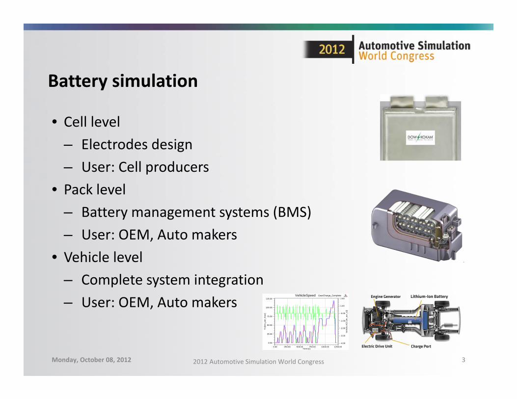
• Cell level– Electrodes design– User: Cell producers
• Pack level– Battery management systems (BMS)– User: OEM, Auto makers
• Vehicle level– Complete system integration– User: OEM, Auto makers
Monday, October 08, 2012 2012 Automotive Simulation World Congress 3
0.00 250.00 500.00 750.00 1000.00 1250.00Time [s]
0.00
25.00
50.00
75.00
100.00
125.00
Y1
[km
_per
_hou
r]
-4.00
-3.00
-2.00
-1.00
-0.00
1.00
2.00
Veh
icle
.AC
C [m
_per
_s2]
GearChange_CompleteVehicleSpeed ANSOFT
Battery simulation
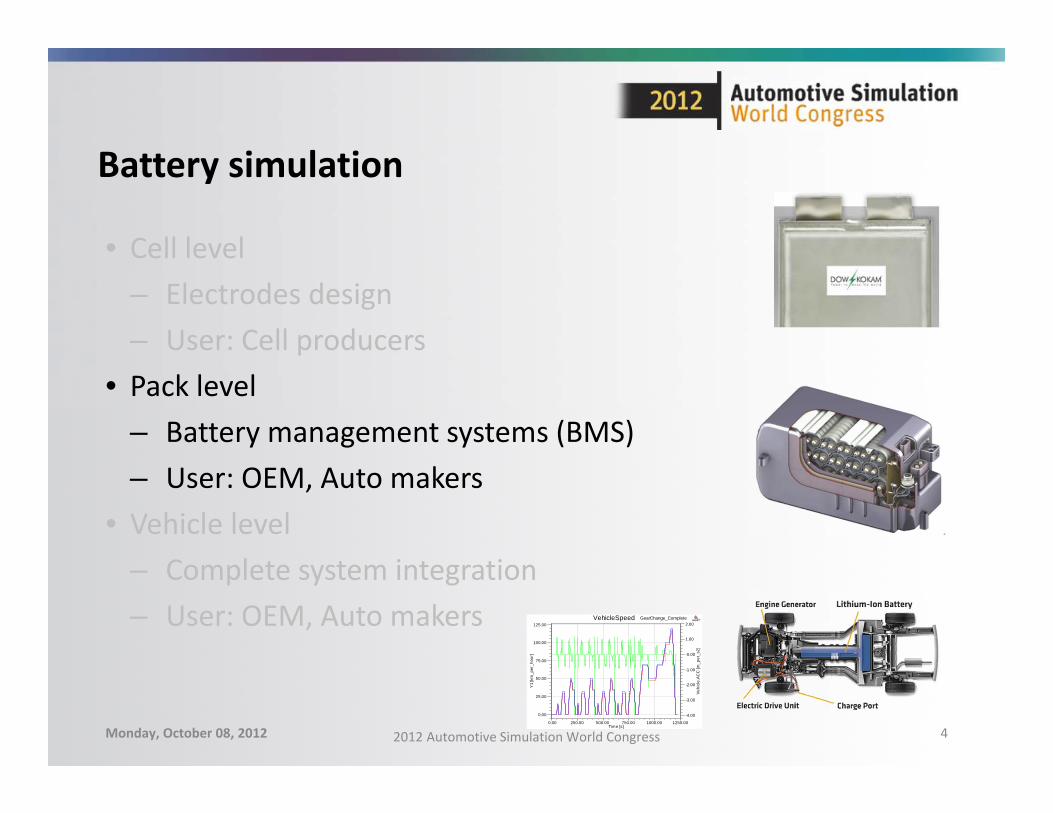
• Cell level– Electrodes design– User: Cell producers
• Pack level– Battery management systems (BMS)– User: OEM, Auto makers
• Vehicle level– Complete system integration– User: OEM, Auto makers
Monday, October 08, 2012 2012 Automotive Simulation World Congress 4 0.00 250.00 500.00 750.00 1000.00 1250.00
Time [s]
0.00
25.00
50.00
75.00
100.00
125.00
Y1
[km
_per
_hou
r]
-4.00
-3.00
-2.00
-1.00
-0.00
1.00
2.00
Veh
icle
.AC
C [m
_per
_s2]
GearChange_CompleteVehicleSpeed ANSOFT
Battery pack level: Electrical predictions
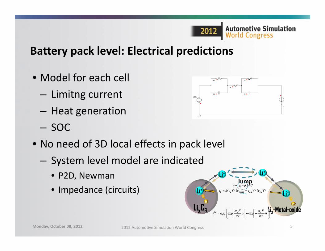
• Model for each cell– Limitng current– Heat generation– SOC
• No need of 3D local effects in pack level– System level model are indicated
• P2D, Newman• Impedance (circuits)
Monday, October 08, 2012 2012 Automotive Simulation World Congress 5
C1
R1
UOCV
I1
RI
R2
C2
0
Li+
eLi+
Li+ Li+
LixC6LixC6 Lix-Metal-oxideLix-Metal-oxidee
Jump
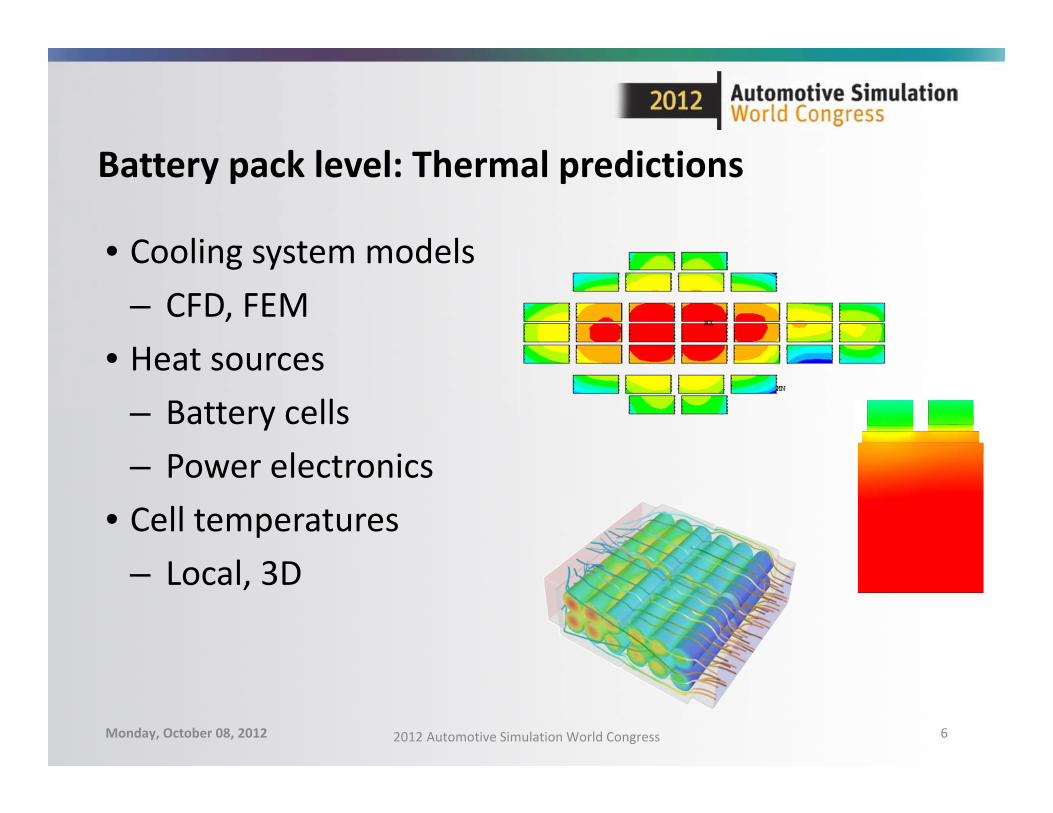
Battery pack level: Thermal predictions
• Cooling system models– CFD, FEM
• Heat sources– Battery cells– Power electronics
• Cell temperatures– Local, 3D
Monday, October 08, 2012 2012 Automotive Simulation World Congress 6
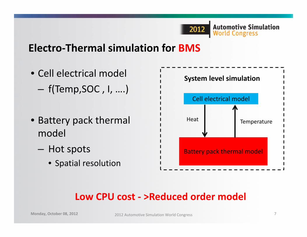
Electro‐Thermal simulation for BMS
• Cell electrical model– f(Temp,SOC , I, ….)
• Battery pack thermal model– Hot spots
• Spatial resolution
Monday, October 08, 2012 2012 Automotive Simulation World Congress 7
Cell electrical model
Battery pack thermal model
Heat Temperature
System level simulation
Low CPU cost ‐ >Reduced order model
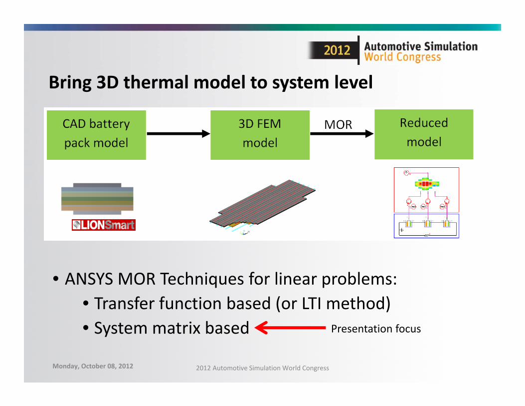
Bring 3D thermal model to system level
• ANSYS MOR Techniques for linear problems: • Transfer function based (or LTI method)• System matrix based Presentation focus
Monday, October 08, 2012 2012 Automotive Simulation World Congress
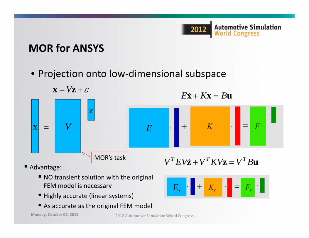
MOR for ANSYS
• Projection onto low‐dimensional subspace zx V
x V
z
=
uxx BKE
uzz BVKVVEVV TTT
E
Er
Advantage: NO transient solution with the original FEM model is necessary Highly accurate (linear systems) As accurate as the original FEM model
MOR’s task
Monday, October 08, 2012 2012 Automotive Simulation World Congress
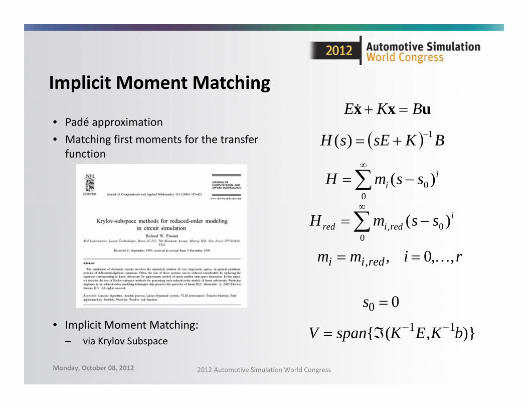
Implicit Moment Matching
• Padé approximation• Matching first moments for the transfer
function
• Implicit Moment Matching:– via Krylov Subspace
0
0 )( ii ssmH
mi mi,red , i 0,,r
BKsEsH 1)(
0
0, )( iredired ssmH
s0 0
V span{(K1E,K1b)}
uxx BKE
Monday, October 08, 2012 2012 Automotive Simulation World Congress
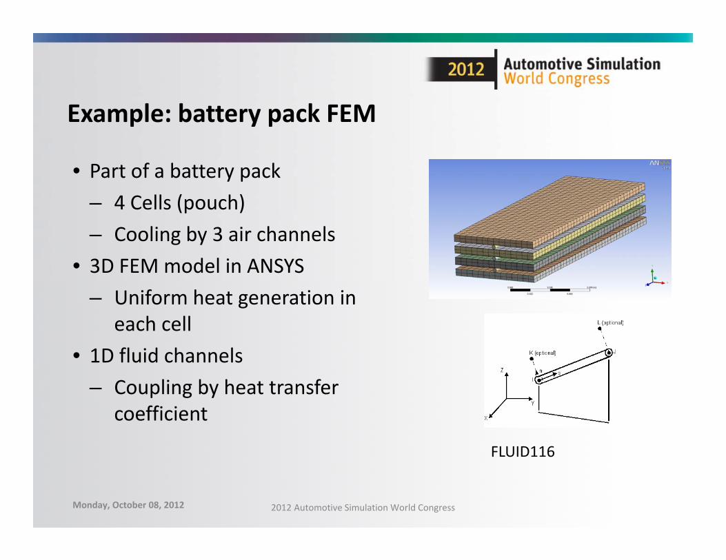
Example: battery pack FEM
• Part of a battery pack– 4 Cells (pouch)– Cooling by 3 air channels
• 3D FEM model in ANSYS– Uniform heat generation in
each cell• 1D fluid channels
– Coupling by heat transfer coefficient
FLUID116
Monday, October 08, 2012 2012 Automotive Simulation World Congress

Reduced vs full solution
Reduced Full
Simulation time [s] 4000 4000 (100 time steps)
Dimension 40 (10 x Input) 48500 elements
CPU time [s] <1 ~20 min
0000
Cell1Cell2Cell3Cell4 T_Ref
HVALUE=0
HVALUE=0
HVALUE=0
VALUE=20HVALUE=10
0.00 1000.00 2000.00 3000.00 4000.00Time [s]
0.00
0.50
1.00
Tem
pera
ture
[cel
]
Curve InfoTCell1.T
TR
ansys_Cell1ImportedError <1%
Step response of 1W per cell
Monday, October 08, 2012 2012 Automotive Simulation World Congress
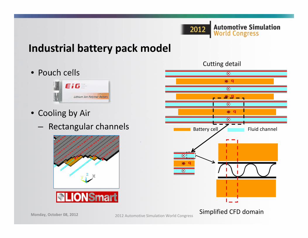
Industrial battery pack model
• Pouch cells
• Cooling by Air– Rectangular channels Battery cell Fluid channel
Cutting detail
Simplified CFD domainMonday, October 08, 2012 2012 Automotive Simulation World Congress
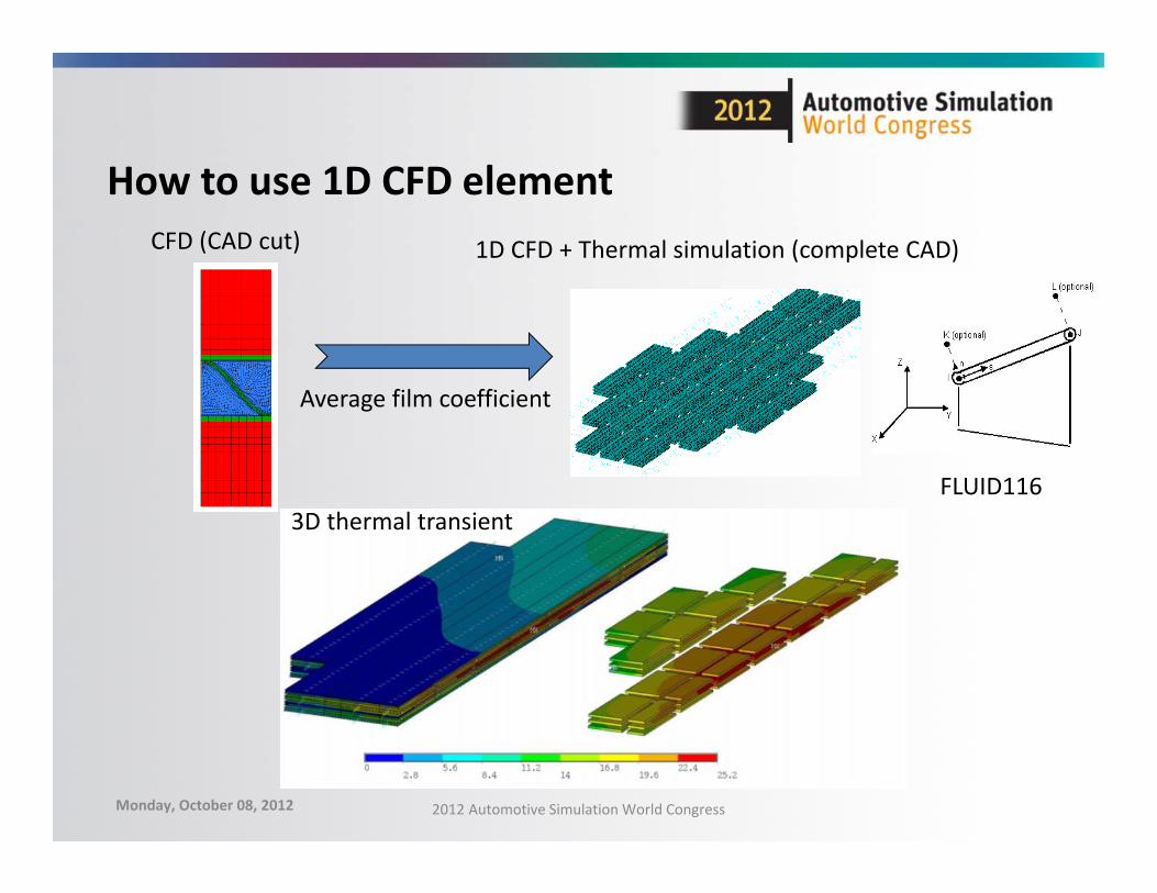
How to use 1D CFD elementCFD (CAD cut) 1D CFD + Thermal simulation (complete CAD)
Average film coefficient
FLUID1163D thermal transient
Monday, October 08, 2012 2012 Automotive Simulation World Congress
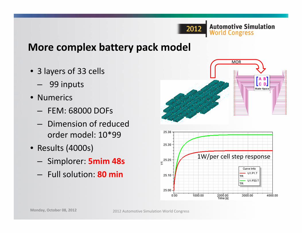
More complex battery pack model
• 3 layers of 33 cells – 99 inputs
• Numerics– FEM: 68000 DOFs– Dimension of reduced
order model: 10*99• Results (4000s)
– Simplorer: 5mim 48s– Full solution: 80 min
1W/per cell step response
MOR
Monday, October 08, 2012 2012 Automotive Simulation World Congress
C1
R1
UOCV
I1
RI
R2
C2
0
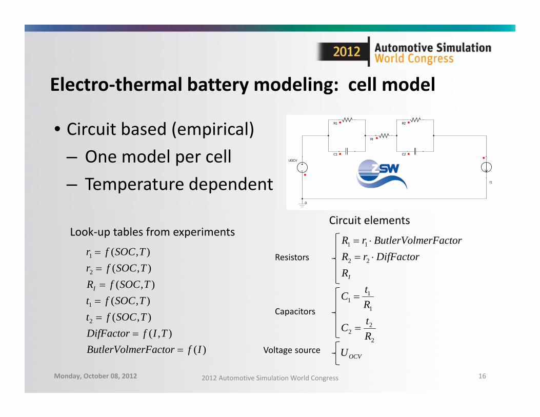
Electro‐thermal battery modeling: cell model
• Circuit based (empirical)– One model per cell– Temperature dependent
Monday, October 08, 2012 2012 Automotive Simulation World Congress 16
)(),(
),(),(),(
),(),(
2
1
2
1
IferFactorButlerVolmTIfDifFactor
TSOCftTSOCftTSOCfR
TSOCfrTSOCfr
I
OCV
I
URtC
RtC
RDifFactorrR
erFactorButlerVolmrR
2
22
1
11
22
11
Look‐up tables from experimentsCircuit elements
Resistors
Capacitors
Voltage source
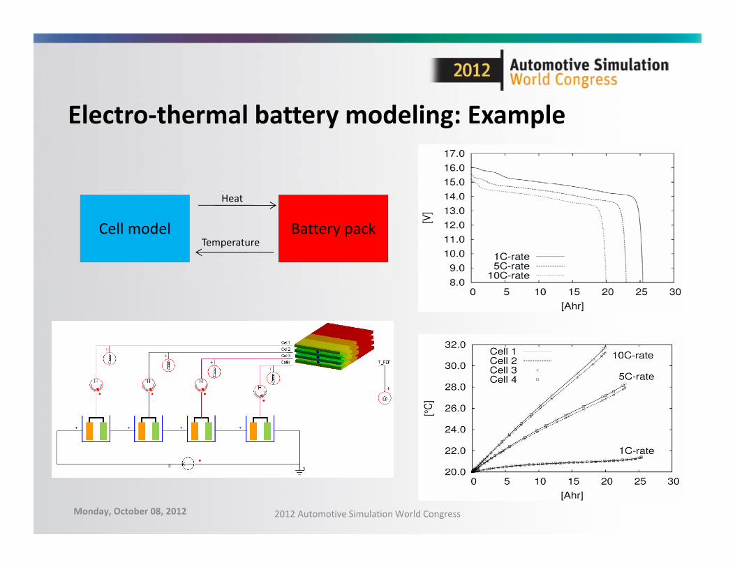
Electro‐thermal battery modeling: Example
• Series connection of 4 cells
Cell model Battery pack
Heat
Temperature
Monday, October 08, 2012 2012 Automotive Simulation World Congress

Recover the Temperature field
• From system results back to 3D whenever desired– Expansion pass
x V
z
=
A
B
C
Monday, October 08, 2012 2012 Automotive Simulation World Congress
1W/per cell step response, and recovering instants
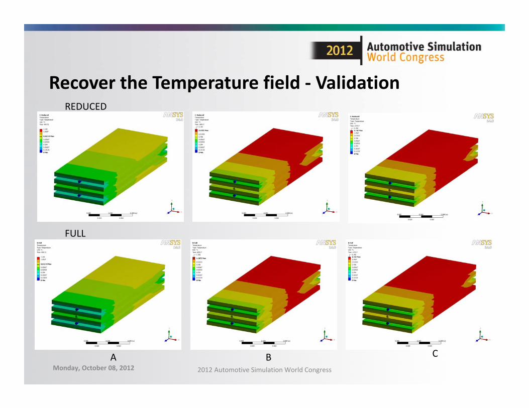
Recover the Temperature field ‐ Validation
A B C
REDUCED
FULL
Monday, October 08, 2012 2012 Automotive Simulation World Congress
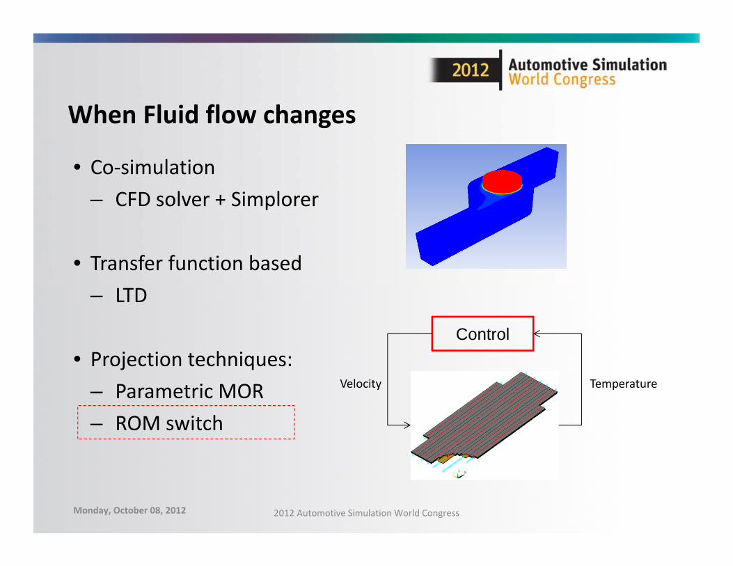
When Fluid flow changes
• Co‐simulation– CFD solver + Simplorer
• Transfer function based– LTD
• Projection techniques:– Parametric MOR– ROM switch
Control
TemperatureVelocity
Monday, October 08, 2012 2012 Automotive Simulation World Congress
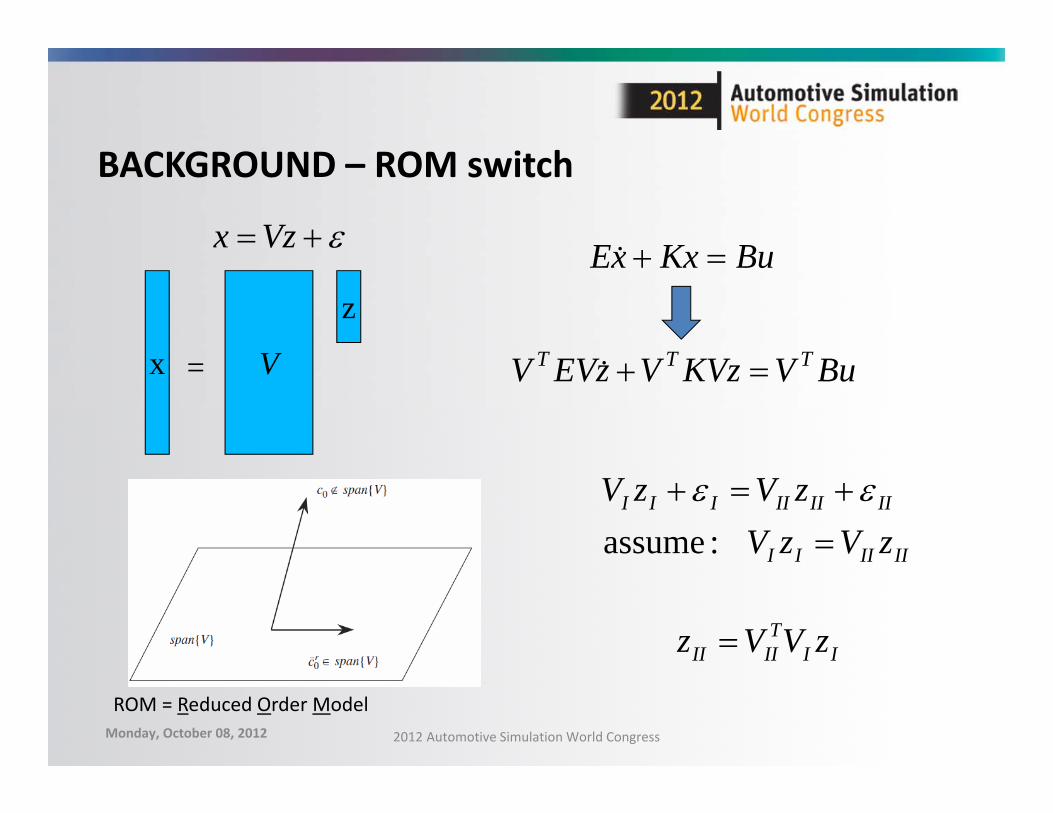
BACKGROUND – ROM switch
IIIIII
IIIIIIIII
zVzVzVzV
:assume
Vzx
x V
z
=
BuKxxE
BuVKVzVzEVV TTT
ROM = Reduced Order Model
IITIIII zVVz
Monday, October 08, 2012 2012 Automotive Simulation World Congress
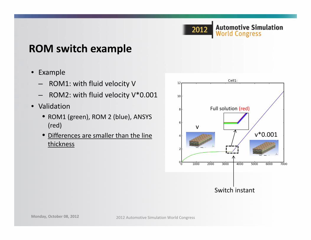
ROM switch example
• Example– ROM1: with fluid velocity V– ROM2: with fluid velocity V*0.001
• Validation• ROM1 (green), ROM 2 (blue), ANSYS (red)
• Differences are smaller than the line thickness
vv*0.001
Switch instant
Full solution (red)
Monday, October 08, 2012 2012 Automotive Simulation World Congress
Summary
• Efficient electro‐thermal simulation by reduction of THERMAL models
• MOR with projection techniques by moment matching– Automatic MOR from ANSYS to Simplorer
• Complex models with more inputs are feasible• Field values (Temperature) recovering from system solution
• ROM switch for changing conditions in the system matrices (velocity)
Monday, October 08, 2012 2012 Automotive Simulation World Congress 23
Acknowledgments
• Evgeny Rudnyi– CADFEM GmbH
• Xiao Hu– ANSYS Inc
• AiF ZIM– Funding project KF2613901WD0
Monday, October 08, 2012 2012 Automotive Simulation World Congress 24