electrokinetic remediation of nickel from low permeability soil
TRANSCRIPT

Int. J. Electrochem. Sci., 6 (2011) 4264 - 4275
International Journal of
ELECTROCHEMICAL SCIENCE
www.electrochemsci.org
Electrokinetic Remediation of Nickel From Low Permeability
Soil
M. Saleem1, M. H. Chakrabarti
2, M. F. Irfan
2, S. A. Hajimolana
2, M. A. Hussain
2,
B. H. Diya’uddeen2,*
, W. M. A. W. Daud2
1 Principal Engineer, Karachi Institute of Power Engineering, Karachi-75400, Pakistan.
2 Department of Chemical Engineering, Faculty of Engineering, University of Malaya, Kuala Lumpur,
50603, Malaysia. Tel: (+603) 7967 5292; fax: (+603) 7967 5319. *E-mail: [email protected]
Received: 25 July 2011 / Accepted: 18 August 2011 / Published: 1 September 2011
Electrokinetic remediation of nickel from low permeability soil using titanium electrodes having inter-
electrode spacing of 10 cm was carried out in a cylindrical reactor. The influences of current density,
voltage gradient and electrolyte pH were investigated upon removal efficiency for 60 h experimental
runs. Efficiency improved from 49.3% to 57.2% when the current density was increased from 4.36
mA/cm2 to 13.1 mA/cm
2. Furthermore, an enhancement in efficiency from 38.5% to 54.3% was
observed when voltage gradient increased from 1 V/cm to 2 V/cm (at 13.1 mA/cm2). Further increase
in voltage gradient to 2.5 V/cm improved efficiency during initial runs. However, an overall reduction
of 3.2% was observed after 60 h of operation in comparison to that obtained at 2 V/cm. This may be
attributed to precipitation and localized accumulation of metallic ions. An inverse relationship between
efficiency and electrolyte pH was also observed (at 13.1 mA/cm2 and 2 V/cm). Although a removal of
74.1% was achieved at pH = 4.5, the system required optimization as the nickel content in treated soil
was above the maximum values given in international standards.
Keywords: Electrokinetic process; Nickel; Low permeability soil; Removal efficiency; Current
density.
1. INTRODUCTION
In general, soil contamination is placing human health at a great risk. Soil contamination is
becoming a key environmental issue, due to its importance in ecosystems, and the influence it has on
the quality of ground water, plants and food [1, 2]. Some of the most common and most damaging
types of soil contaminants are metals. Generally, during routine operations or accidental spills in
industry soil may be contaminated with metals. Once metal contaminates the soil, it can have complex
Int. J. Electrochem. Sci., Vol. 6, 2011
4265
interactions with natural binders that can lead to both short (delaying the normal hydration reaction)
and long (release of the heavy metals in groundwater) term problems. Presence of heavy metals in soil
has great concern with respect to human health and safety [2].
Application of electrokinetic process for the removal of contaminant may vary mainly due to
the variation in soil type and type of contaminant in the soil [3, 4]. Electrokinetic remediation can be
made more effective by optimizing the operating parameters of the process like applied current,
applied voltage, and pH of electrolyte [5]. Remediation of low permeable soils is usually difficult by
most traditional methods such as soil washing [6]. Electrokinetic remediation method, on the other
hand, is a very effective technique when applied to fine-grained soils and soils with low hydraulic
conductivity for the removal of pollutants [7, 8]. Electrokinetic remediation uses electric current to
extract a variety of organic and inorganic pollutants from low permeable soils. Extensive research has
been done on directing the contaminants migration to where remediation may be more easily
achievable [5]. A combination of electrokinetic techniques with other processes such as electro-
Fenton, bioremediation and phytoremediation has been tested to enhance pollutant removal [9 - 14]. In
order to improve the transport of contaminants and process efficiency various additives such as
solvents, chelating agents and surfactants have been used in other studies [14 - 16]. In addition, these
researchers have indicated the need to explore the influence of operating parameters on the removal
efficiency of the process.
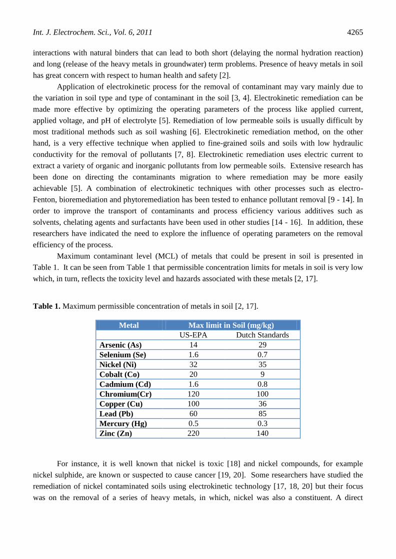
Maximum contaminant level (MCL) of metals that could be present in soil is presented in
Table 1. It can be seen from Table 1 that permissible concentration limits for metals in soil is very low
which, in turn, reflects the toxicity level and hazards associated with these metals [2, 17].
Table 1. Maximum permissible concentration of metals in soil [2, 17].
Metal Max limit in Soil (mg/kg)
US-EPA Dutch Standards
Arsenic (As) 14 29
Selenium (Se) 1.6 0.7
Nickel (Ni) 32 35
Cobalt (Co) 20 9
Cadmium (Cd) 1.6 0.8
Chromium(Cr) 120 100
Copper (Cu) 100 36
Lead (Pb) 60 85
Mercury (Hg) 0.5 0.3
Zinc (Zn) 220 140
For instance, it is well known that nickel is toxic [18] and nickel compounds, for example
nickel sulphide, are known or suspected to cause cancer [19, 20]. Some researchers have studied the
remediation of nickel contaminated soils using electrokinetic technology [17, 18, 20] but their focus
was on the removal of a series of heavy metals, in which, nickel was also a constituent. A direct

Int. J. Electrochem. Sci., Vol. 6, 2011
4266
electrokinetic remediation of nickel from low permeable soil appears to be limited in the literature
(especially for the South Asian region, i.e., Pakistan) considering the fact that levels of nickel present
in soils from the Sindh region are beyond the recommended limit as reported by Yawar et al. [21].
Some studies conducted in Pakistan have shown higher concentrations of nickel in water and
sediment samples collected from various localities along Karachi’s coast (as a consequence of
discharges from tanneries, refineries and power stations). Mangrove habitats in the vicinity of Karachi
serve as a sink for nickel and a variety of other heavy metals [22, 23]. The sediments act as major traps
for metals followed by mangrove plants. Detrital silicates and sulphides are the principal carriers of
iron and nickel thereby making sediments a long term contaminant sinks.
The aim of the present work is to study the influence of some operating parameters on the
removal of nickel from a low permeability soil in Karachi (Pakistan) using electrokinetic process. The
effects of studied process variables are discussed in detail.
2. MATERIALS AND METHOD
2.1. Description of the soil
Low permeability soil was collected from the Hawks bay beach in Karachi. The soil sample
was classified as sandy soil (97.6% sand, 2% silt and 0.4% clay) by the Unified Classification System
procedure (based on ASTM D-2487) with 6.17% of organic matter (OM) and a cation exchange
capacity (CEC) of 25.2 mmol/kg. The soil was passed through a 2 mm sieve to remove stones,
branches and any other coarse material. The soil sample was then washed with distilled water
followed by 2% commercial sulphuric acid (Merck, Pakistan) to remove organic components from the
soil. Rinsing with distilled water was repeated. Properties of the soil such as pH and moisture content
were determined in the laboratory using standard methods [24]. An initial concentration of 200 mg/kg
of nickel was detected in the soil sample, which was beyond the limits specified by Yawar et al. [21].
Hydraulic conductivity of the soil was measured in the laboratory as reported in the literature [25] and
was found to be in the range of 10-10
to 10-9
m/s. Initial pH of the soil was 5.5 as shown in Table 2.
Table 2. Properties of soil used
Parameter (units) Value
Moisture content, % 20 – 25
Particle size, mm < 2
Soil pH (except in pH experiments) 5 – 5.5
Soil temperature, °C 28 – 30
Hydraulic conductivity, m/s 10-10
– 10-9
Int. J. Electrochem. Sci., Vol. 6, 2011
4267
2.2. Reactor Design
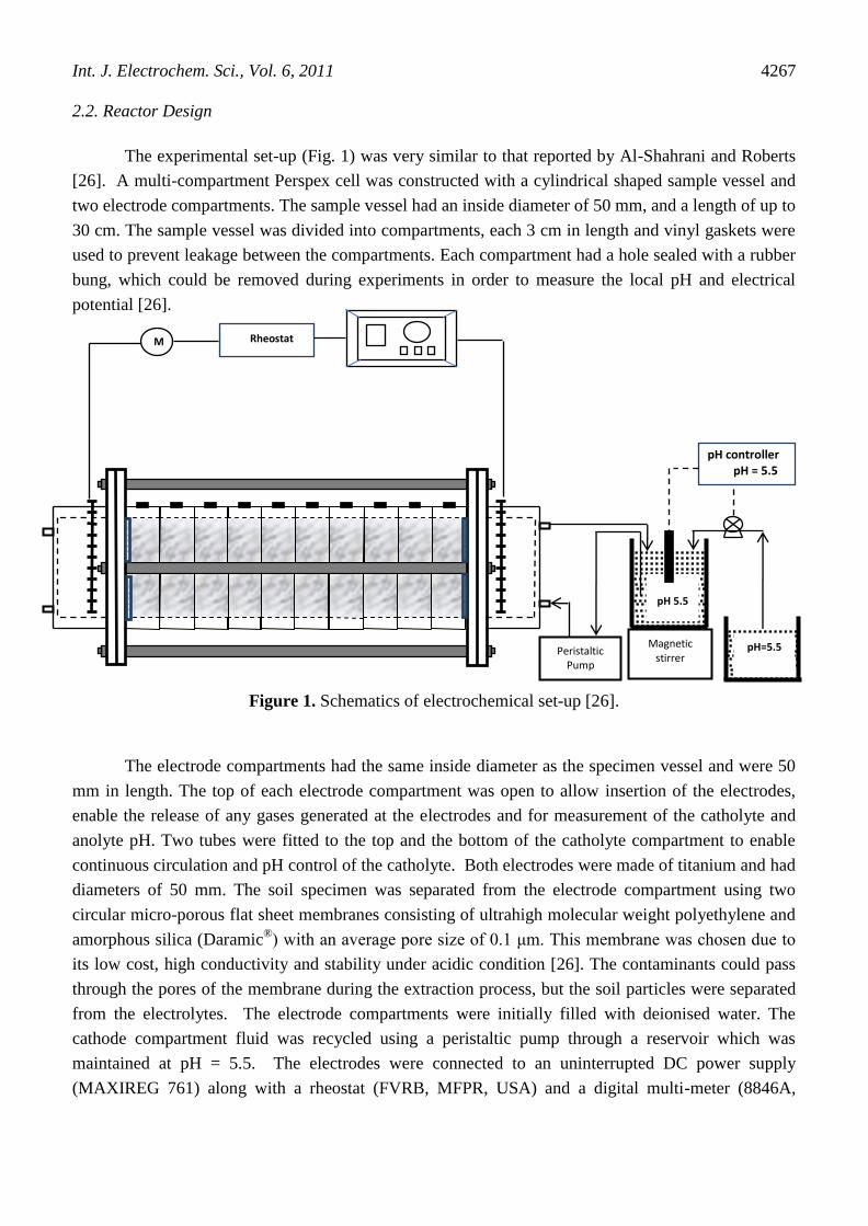
The experimental set-up (Fig. 1) was very similar to that reported by Al-Shahrani and Roberts
[26]. A multi-compartment Perspex cell was constructed with a cylindrical shaped sample vessel and
two electrode compartments. The sample vessel had an inside diameter of 50 mm, and a length of up to
30 cm. The sample vessel was divided into compartments, each 3 cm in length and vinyl gaskets were
used to prevent leakage between the compartments. Each compartment had a hole sealed with a rubber
bung, which could be removed during experiments in order to measure the local pH and electrical
potential [26].
Figure 1. Schematics of electrochemical set-up [26].
The electrode compartments had the same inside diameter as the specimen vessel and were 50
mm in length. The top of each electrode compartment was open to allow insertion of the electrodes,
enable the release of any gases generated at the electrodes and for measurement of the catholyte and
anolyte pH. Two tubes were fitted to the top and the bottom of the catholyte compartment to enable
continuous circulation and pH control of the catholyte. Both electrodes were made of titanium and had
diameters of 50 mm. The soil specimen was separated from the electrode compartment using two
circular micro-porous flat sheet membranes consisting of ultrahigh molecular weight polyethylene and
amorphous silica (Daramic®) with an average pore size of 0.1 μm. This membrane was chosen due to
its low cost, high conductivity and stability under acidic condition [26]. The contaminants could pass
through the pores of the membrane during the extraction process, but the soil particles were separated
from the electrolytes. The electrode compartments were initially filled with deionised water. The
cathode compartment fluid was recycled using a peristaltic pump through a reservoir which was
maintained at pH = 5.5. The electrodes were connected to an uninterrupted DC power supply
(MAXIREG 761) along with a rheostat (FVRB, MFPR, USA) and a digital multi-meter (8846A,
Peristaltic Pump
Magnetic stirrer
pH 5.5
pH controller
pH = 5.5
M Rheostat
pH=5.5
Int. J. Electrochem. Sci., Vol. 6, 2011
4268
Fluke, USA). Inter-electrode spacing was kept at 10 cm in each run. A separate electrolyte tank was
used to provide a controlled flow of 0.5 ml/h using a peristaltic pump (Precision BT-50SER, China).
Each experimental run lasted for at least 60 h.
2.3. Experimental Procedures
Prior to the start of testing the electrochemical reactor was conditioned (after packing the
reactor with soil) by equilibrating it with tap water and applying a zero hydraulic head across it for 24
h. The soil packing procedure was identical to that reported earlier for the electrochemical remediation
of caesium [26]. After the electrokinetic cell was conditioned the power supply was turned on and the
reactor was set to operate at various different parameters as described in Table 3. All the experiments
were performed in duplicate to evaluate test reproducibility in a similar manner to literature reported
methods [27]. However, the highest nickel removal efficiencies were reported for both runs under
identical conditions.
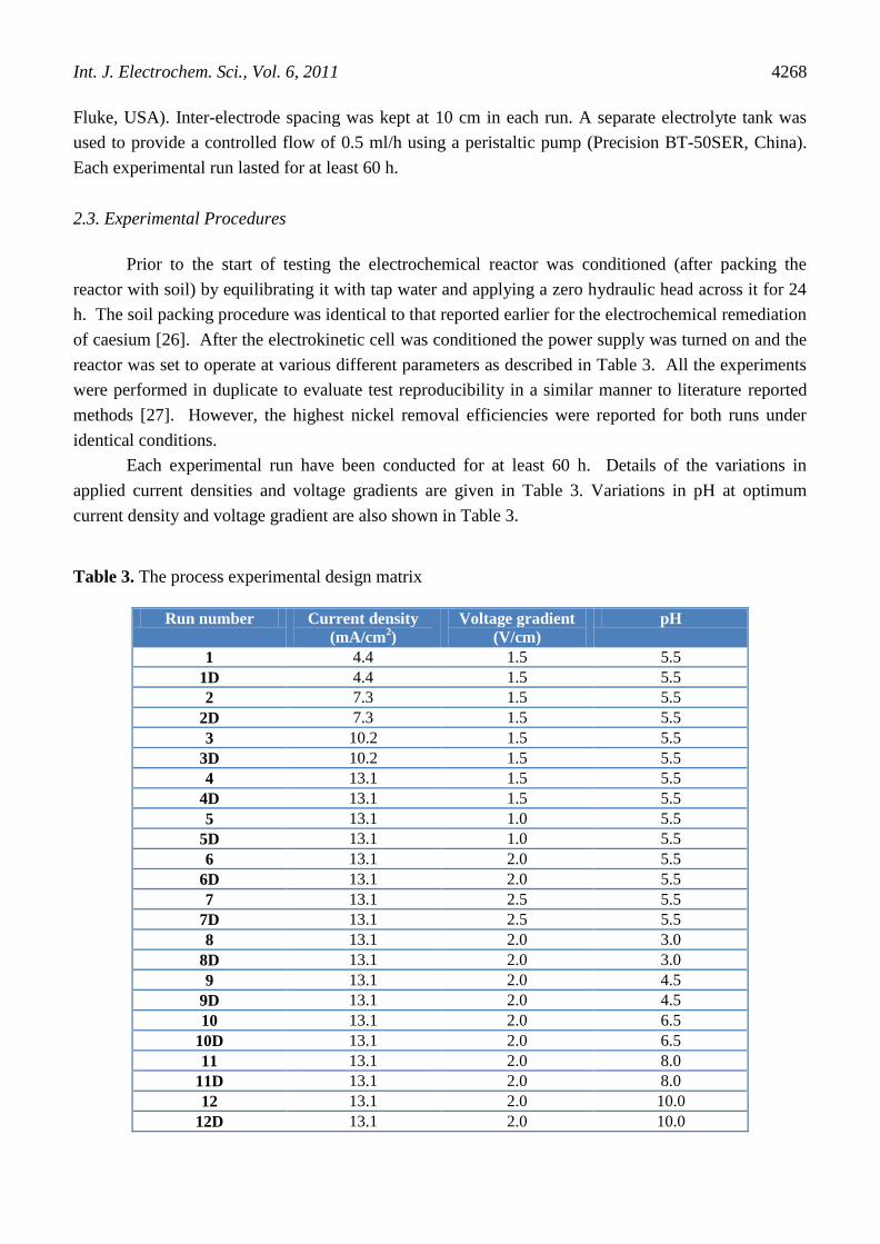
Each experimental run have been conducted for at least 60 h. Details of the variations in
applied current densities and voltage gradients are given in Table 3. Variations in pH at optimum
current density and voltage gradient are also shown in Table 3.
Table 3. The process experimental design matrix
Run number Current density
(mA/cm2)
Voltage gradient
(V/cm)
pH
1 4.4 1.5 5.5
1D 4.4 1.5 5.5
2 7.3 1.5 5.5
2D 7.3 1.5 5.5
3 10.2 1.5 5.5
3D 10.2 1.5 5.5
4 13.1 1.5 5.5
4D 13.1 1.5 5.5
5 13.1 1.0 5.5
5D 13.1 1.0 5.5
6 13.1 2.0 5.5
6D 13.1 2.0 5.5
7 13.1 2.5 5.5
7D 13.1 2.5 5.5
8 13.1 2.0 3.0
8D 13.1 2.0 3.0
9 13.1 2.0 4.5
9D 13.1 2.0 4.5
10 13.1 2.0 6.5
10D 13.1 2.0 6.5
11 13.1 2.0 8.0
11D 13.1 2.0 8.0
12 13.1 2.0 10.0
12D 13.1 2.0 10.0
Int. J. Electrochem. Sci., Vol. 6, 2011
4269
In order to solubilize the metal hydroxide and carbonates formed, or different species adsorbed
on the soil particles, as well as to protonate organic functional groups during the electrokinetic process,
acetic acid (Merck) is added to the cathodic compartment [18]. Due to possessing negative charges,
the organic acids migrate towards the anodic compartment. As a result, sodium hydroxide (Merck) is
added into this chamber to neutralize the acid. However, to ensure high nickel removal, water has
been used as a purging solution at both the anode and cathode initially, followed by the use of acetic
acid as the cathode purging solution and NaOH as the anode purging solution [28].
After calibration with a standard pH solution, the pH of the electrolytes was measured by a pH
meter (Istek Inc., Model 76P) in an identical manner to that reported by Al-Shahrani and Roberts [26].
The average value of the two experiment samples was used in a similar manner to the procedure
followed in the literature [18].
2.4. Post Run Soil Analysis
At the end of the electrokinetic process anode and cathode end solutions have been collected
and all liquid and solid samples are digested according to EPA method 3015 and 3051, respectively
[29]. Collected soil samples have been analyzed (in triplicate) for residual nickel concentration by
using Atomic Absorption Spectrophotometer (AAS M6, Thermo Fisher Scientific) following standard
procedures [24]. This is followed by the measurement of soil pH. Afterwards the total energy
consumption and the current efficiency of the electrokinetic process are calculated as given in the
literature [30].
3. RESULTS AND DISCUSSION
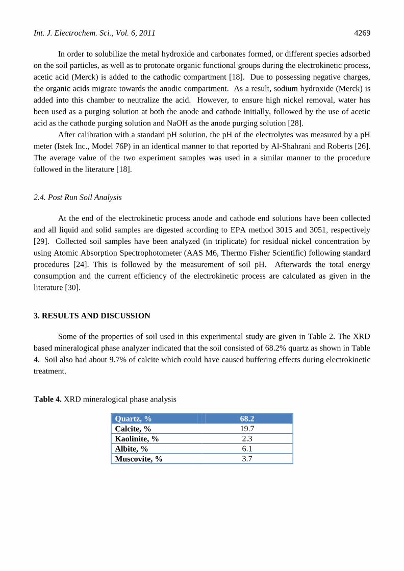
Some of the properties of soil used in this experimental study are given in Table 2. The XRD
based mineralogical phase analyzer indicated that the soil consisted of 68.2% quartz as shown in Table
4. Soil also had about 9.7% of calcite which could have caused buffering effects during electrokinetic
treatment.
Table 4. XRD mineralogical phase analysis
Quartz, % 68.2
Calcite, % 19.7
Kaolinite, % 2.3
Albite, % 6.1
Muscovite, % 3.7

Int. J. Electrochem. Sci., Vol. 6, 2011
4270
3.1. Effect of applied current density on removal efficiency
It was found that in general, the efficiency of the process increased with the increase in applied
current density from 4.4 to 13.1 mA/cm2 during 60 h of runs (Fig. 2). The removal efficiency was high
during the first 10 h but dampened over time. The removal efficiency of nickel was c.a. 44.2 %, 45.7
%, 48.1 % and 52.1 % after 48 h of electrokinetic treatment with current densities of 4.4 mA/cm2, 7.3
mA/cm2, 10.2 mA/cm
2 and 13.1 mA/cm
2, respectively. Nickel removal after 60 h of run reached to
49.3%, 51.9%, 56.1% and 57.2% while using current densities of 4.4 mA/cm2, 7.3 mA/cm
2, 10.2
mA/cm2
and 13.1 mA/cm2, respectively. These percentages are based on the amount of nickel
collected in the catholyte, rather than the nickel concentrations measured in the soil at the end of the
experiment. A material balance on nickel was performed and the results were summarized in Table 5.
A maximum discrepancy of 2.0% indicated that the material balance was sound.
0
10
20
30
40
50
60
13.110.27.34.4
Rem
ova
l eff
icie
ncy
(%
)
Current density (mA/cm2)
1 h
2 h
4 h
8 h
12 h
20 h
30 h
40 h
50 h
60 h
Figure 2. Temporal effect of applied current density on the removal efficiency nickel from soil by
means of Electrokinetic process.
Results showed that removal efficiency was dependent on the total energy input to the process
(Table 5). The removal efficiency achieved in the present work was better than those achieved under
similar conditions in an earlier study [31] and consistent with the current literature [32].
Conductivity was initially high probably due to the presence of more dissolved species in the
porous soil matrix. Therefore, measured current increased initially as the dissolved ions and desorbed
metals came into the solution phase and transported through the soil matrix in response to
electroosmosis and electromigration [17]. However, with the passage of time when little ionic species

Int. J. Electrochem. Sci., Vol. 6, 2011
4271
and dissolved materials were available in solution phase, conductivity decreased so the rate of removal
declined. Higher values of current densities were not applied because previous work indicated that
temperature of soil could rise thereby increasing energy usage [7].
Table 5. Material balance of nickel removal experiments, total energy consumption and current
efficiency
Run
number
Ni collected
in anolyte
(mg)
Ni
remaining
in cell
(mg)
Ni collected in
catholyte (mg)
Total Ni
(mg)
Discrepancy
in material
balance (%)
Energy usage
(kWh)
Current efficiency (%)
1 < 0.1 100 97 17 1.5 0.00389 105.7
1D < 0.1 100 98 198 1.0 0.00389 105.7
2 < 0.1 96 103 199 0.5 0.00645 63.7
2D < 0.1 94 102 196 2.0 0.00645 63.7
3 < 0.1 88 111 199 0.5 0.00902 45.6
3D < 0.1 88 111 199 0.5 0.00902 45.6
4 < 0.1 85 113 198 1.0 0.01158 35.5
4D < 0.1 84 112 196 2.0 0.01158 35.5
5 < 0.1 122 75 197 1.5 0.00772 35.5
5D < 0.1 121 75 196 2.0 0.00772 35.5
6 < 0.1 84 112 196 2.0 0.01544 35.5
6D < 0.1 84 113 197 1.5 0.01544 35.5
7 < 0.1 98 101 199 0.5 0.01930 35.5
7D < 0.1 97 101 198 1.0 0.01930 35.5
8 < 0.1 53 145 198 1.0 0.01544 35.5
8D < 0.1 53 145 198 1.0 0.01544 35.5
9 < 0.1 53 144 197 1.5 0.01544 35.5
9D < 0.1 54 145 199 0.5 0.01544 35.5
10 < 0.1 74 122 196 2.0 0.01544 35.5
10D < 0.1 75 123 198 1.0 0.01544 35.5
11 < 0.1 112 85 197 1.5 0.01544 35.5
11D < 0.1 113 86 199 0.5 0.01544 35.5
12 < 0.1 133 63 196 2.0 0.01544 35.5
12D < 0.1 134 64 198 1.0 0.01544 35.5
3.2.Effect of applied voltage gradient on removal efficiency
It was observed that the applied voltage gradient was positively related to the process
efficiency at a constant current density of 13.1 mA/cm2. It can be seen from Fig. 3 that the removal of
nickel from the soil increased with the increase in applied voltage gradient. However, maximum
removal of 54.3% was achieved with 2 V/cm after 60 h of run. Further increase in applied voltage
gradient (2.5 V/cm) initially improved the removal efficiency, however, cumulative removal after 60 h
of experimental run showed a 3.2% reduction from the efficiency obtained when 2 V/cm was
employed. This effect was probably due to the enhanced movement of ions in the soil matrix with the
increase in potential difference. However, soil temperature rose with the increase in applied voltage
gradient and resulted in the localized accumulation of metallic ions in the soil that reduced mobility.

Int. J. Electrochem. Sci., Vol. 6, 2011
4272
This in turn resulted in diminishing of soil pore water by thermally induced gradients that may have
suppressed the electrokinetic process [7]. Consequently, with the decrease in moisture content in some
of the soil pockets, current flow decreased resulting in the reduction of removal efficiency.
Figure 3. Temporal effect of voltage gradient on the removal efficiency of nickel from soil by means
of Electrokinetic process.
3.3. Effect of electrolyte pH on removal efficiency
It was found that the removal efficiency of electrokinetic process decreased with the increase in
pH of electrolyte passing through the porous media (at a constant current density of 13.1 mA/cm2
and
voltage gradient of 2 V/cm). Maximum removal efficiency of 74.1% was noted at a pH value of 4.5,
however, further reduction in pH did not improve the efficiency significantly as shown in Fig. 4.
Result was in line with the fact that generally at a pH of 8.0 nickel has a solubility of 70 mg/L and at a
pH of 10.2 the solubility is 0.1 mg/L [33, 34]. It was evident from Fig. 4 that the removal efficiency of
the electrokinetic process decreased drastically when the pH value increased from 6.5 and showed
removal efficiency of only 33.1% at a pH of 10. Reduction in removal efficiency at higher pH of
electrolyte may be attributed to alkali fronts near the cathode which produces non-conductive
precipitates. These can retard or stop the migration of ions which in turn results in reduction of
removal efficiency. The formation of a highly resistive band influences the remediation as it causes the
voltage gradient, and hence the pollutant migration, to decrease across the soil. Further work is
required in order to optimize the electrokinetic process. In addition, catholyte conditioning and pre-
treatment of the soil with nitric acid would enhance the removal efficiency as reported by other
workers [32].

Int. J. Electrochem. Sci., Vol. 6, 2011
4273
Since the pH of the catholyte was controlled at constant values, it is not immediately clear how
the acetic acid used effects the pH distribution in the soil. The explanation is probably that the
associated anion added with the acid migrated in the electric field into the soil, thus modifying the
speciation in the pore fluid. In particular, the acetate ions will buffer the acid front migrating from the
anode. In addition, these ions will interact with other adsorbed and dissolved species, so that the
overall effect is complex and difficult to predict. The weaker and more mobile acetate would be
expected to have a stronger buffering effect than other stronger acids, which is consistent with results
reported in the literature [32]. As a consequence a pH distribution was not reproduced in this work.
Figure 4. Temporal effect of electrolyte pH on the removal efficiency of nickel by means of
Electrokinetic process.
4. CONCLUSIONS
The following specific conclusions are drawn on the basis of results obtained during the present
study:
Temporal increase in nickel removal using electrokinetic process is observed during
each 60 h of experimental runs. High removal rates during initial 10 h may be attributed to the higher
conductivity due to more dissolution of species in the porous soil matrix.
Nickel removal is positively related to the applied current density; however, increase is
up to 7.9% when applied current density is increased from 4.4 mA/cm2
to 13.1 mA/cm2.
Int. J. Electrochem. Sci., Vol. 6, 2011
4274
An enhancement in removal efficiency up to 15.9% is observed when voltage gradient
is increased from 1 V/cm to 2 V/cm but further increase doesn’t improve the removal efficiency.
An inverse relationship between the removal efficiency and the pH of electrolyte
solution is observed. It is found that removal of nickel by electrokinetic technology is better with
electrolytes having low pH values as reported in the literature. It is probably due to desorption of metal
ions which is greatest at lower pH and decreases with the increase in pH. Maximum removal efficiency
of the process (74.1%) is achieved at a pH value of 4.5. However, further decrease in soil pH doesn’t
improve the removal efficiency.
From the experimental results obtained, it may be concluded that the optimum
conditions for electrokinetic remediation of nickel from low permeable soil in Karachi are i = 7.3
mA/cm2, voltage gradient = 1.5 V/cm and a pH = 7.
ACKNOWLEDGEMENTS
Authors are grateful to acknowledge the help and support provided by the Karachi Institute of Power
Engineering and University of Malaya (Bright Sparks Funding) during the study period.
References
1. J. Zhang, J. A. Ferdinand, D. J. Vanderheyden, J. M. Skelly, J. L. Innes, Environ. Pollut. 113 (2001)
177.
2. M. Saleem, M. H. Essa, NED Univ. J. Res. 7 (2010) 23.
3. R. A. Shrestha, T. D. Pham, M. Sillanpää, Int. J. Electrochem. Sci. 4 (2009) 1387.
4. C. Ruíz, J. M. Anaya, V. Ramírez, G. I. Alba, M. G. García, A. Carrillo-Chávez, M. M. Teutli, E.
Bustos, Int. J. Electrochem. Sci. 6 (2011) 548.
5. R. E. Saichek, K. R. Reddy, Crit. Rev. Env. Sci. Tech. 35 (2005a) 115.
6. C. Chaiyaraksa, N. Sriwiriyanuphap, Chemosphere. 56 (2004) 1129.
7. M. A Orcino, M. R. Bricka, Electrochemical remediation of heavy metal contaminated soils, John
Wiley & Sons, New York, USA. 1998.
8. H. Moayedi, A. Asadi, B. B. K. Huat, F. Moayedi, S. Kazemian, Int. J. Electrochem. Sci. 6 (2011)
2526.
9. C. Yuan, C. H. Weng, Chemosphere. 57 (2004) 225.
10. S. Suni, E. Malinen, J. Kosonen, H. Silvennoinen, M. Romantschuk, J. Environ. Sci. Health: Part
A. 42 (2007) 277.
11. H. Aboughalma, R. Bi, M. Schlaak, M. J. Environ. Sci. Health: Part A. 43 (2008) 926.
12. M. D Jackson, J. Geophys. Res. 113 (2008) 955.
13. A. Oonnittan, R. A. Shrestha, M. Sillanpää, J. Environ. Sci. Health: Part A. 43 (2008) 894.
14. Z. Zou, R. Qiu, W. Zhang, H. Dong, Z. Zhao, T. Zhang, X. Wei, X. Cai, Environ. Pollut. 157
(2009) 229.
15. Y. C. Kang, C. Yang, X. Huang, J. Colloid Interf. Sci. 253 (2002) 285.
16. R. E. Saichek, K. R. Reddy, J. Env. Eng. Sci. 4 (2005b) 327.
17. V. V. Guaracho, N. M. S. Kaminari, M. J. J. S. Ponte, H. A. Ponte, J. Hazard. Mater. 172 (2009)
1087.
18. J. H. Choi, S. Maruthamuthu, H. G. Lee, T. H. Ha, J. H. Bae, Met. Mater. Int. 15 (2009) 771.
19. L. Koene, L. J. J. Janssen, Electrochim. Acta. 47 (2001) 695.
20. P. Suer, K. Gitye, B. Allard, Environ. Sci. Technol. 37 (2003) 177.
21. W. Yawar, K. Naeem, P. Akhtar, I. Rehana, Sci Inter. 21 (2009) 123.

Int. J. Electrochem. Sci., Vol. 6, 2011
4275
22. M. Sharif, Y. Nergis, M. A. Farooq, American-Eurasian J. Agric. Environ. Sci. 9 (2010) 584.
23. A. H. K. Yousufzai, D. R. Hashmi, A. Salam, J. Chem. Soc. Pak. 20 (1998) 168.
24. L. S. Clesceri, A. E. Greenberg, A. D. Eaton, Standard Methods for the Examination of Water and
Wastewater, American Public Health Association, USA, 1998.
25. E. G. Youngs, P. B. Leeds-Harrison, D. E. Elrick, Soil Tech. 8 (1995) 153.
26. S. S. Al-Shahrani, E. P. L. Roberts, J. Hazard. Mater. 122 (2005) 91.
27. P. R. Buchireddy, R. M. Bricka, D. B. Gent, J. Hazard. Mater. 162 (2009) 490.
28. K. R. Reddy, S. Chinthamreddy, J. Geotech. and Geoenvir. Eng. 129 (2003) 263.
29. U.S. EPA (United States Environmental Protection Agency), Recent Developments for In Situ
Treatment of Metals Contaminated Soils, Office of Solid Waste and Emergency Response
Technology Innovation Office, Washington, DC, 1997.
30. M. Saleem, M. H. Chakrabarti, B. H. Diya’uddeen, Afr. J. Biotech. In Press, 2011.
31. R. K. Freitag, D. B. Brown, 1998. IEEE Trans. Nucl. Sci. 45, 2649.
32. D. H. Kim, B. G. Ryu, S. W. Park, C. Seo, K. Baek, J. Hazard. Mater. 165 (2009) 501.
33. K. R. Reddy, U. S. Parupudi, J. Soil Contamin. 6 (1997) 391.
34. G. Fu, Z. Hu, L. Xie, X. Jin, Y. Xie, Y. Wang, Z. Zhang, Y. Yang, H. Wu, Int. J. Electrochem. Sci. 4
(2009) 1052.
© 2011 by ESG (www.electrochemsci.org)