electromagnetic compatibility of train detection ... iss 1.pdfelectromagnetic compatibility of train...
TRANSCRIPT

Rail Industry StandardRIS-0725-CCSIssue: OneDate: December 2017
ElectromagneticCompatibility of TrainDetection Infrastructurewith Rail Vehicles
Synopsis
This document is a standard onimmunity levels of infrastructure-basedtrain detection systems, to provideelectromagnetic compatibility (EMC)with emissions from trains.
Copyright in the Railway Group documents is owned by RailSafety and Standards Board Limited. All rights are herebyreserved. No Railway Group document (in whole or in part)may be reproduced, stored in a retrieval system, ortransmitted, in any form or means, without the prior writtenpermission of Rail Safety and Standards Board Limited, or asexpressly permitted by law.
RSSB members are granted copyright licence in accordancewith the Constitution Agreement relating to Rail Safety andStandards Board Limited.
In circumstances where Rail Safety and Standards BoardLimited has granted a particular person or organisationpermission to copy extracts from Railway Group documents,Rail Safety and Standards Board Limited accepts noresponsibility for, nor any liability in connection with, the useof such extracts, or any claims arising therefrom. Thisdisclaimer applies to all forms of media in which extractsfrom Railway Group documents may be reproduced.
Published by RSSB
© Copyright 2017Rail Safety and Standards Board Limited
Uncontrolled when printed Document comes into force on 02/12/2017

Issue Record
Issue Date Comments
One 02/12/2017 This document sets out values for EMC parametersfor CCS infrastructure subsystems.
This document will be updated when necessary by distribution of a completereplacement.
Supply
The authoritative version of this document is available at www.rssb.co.uk/railway-group-standards. Enquiries on this document can be forwarded to [email protected].
Rail Industry StandardRIS-0725-CCSIssue: OneDate: December 2017
Electromagnetic Compatibility of TrainDetection Infrastructure with Rail
Vehicles
Page 2 of 41 RSSB
Uncontrolled when printed Document comes into force on 02/12/2017

Contents
Section Description Page
Part 1 Purpose and Introduction 61.1 Purpose 61.2 Background 61.3 Intended use of this document 61.4 Application of this document 71.5 Health and safety responsibilities 71.6 Structure of this document 81.7 Approval and Authorisation 8
Part 2 Requirements for EMC Interface Parameters for Train DetectionSystems 9
2.1 New types of infrastructure-based train detection system 92.2 New and modified track circuit equipment of legacy design types 9
Part 3 Track Circuits on AC Electrified Lines 113.1 DC (AC immune) track circuits 113.2 Reed track circuits (AC lines) 133.3 TI 21 / EBI Track 200 (AC lines) 14
Part 4 Track Circuits on DC Electrified Lines 214.1 50 Hz track circuits 214.2 Reed track circuits (DC lines) 234.3 TI 21 / EBI Track 200 (DC lines) 244.4 FS2600 track circuits 26
Part 5 Track Circuits Used on Both AC and DC Electrified Lines 295.1 EBI Track 400 295.2 HVI track circuits 34
Part 6 Track Circuits on Non-Electrified Lines 356.1 Track circuits used on non-electrified lines 35
Definitions 38
References 40
Electromagnetic Compatibility of TrainDetection Infrastructure with RailVehicles
Rail Industry StandardRIS-0725-CCSIssue: OneDate: December 2017
RSSB Page 3 of 41
Uncontrolled when printed Document comes into force on 02/12/2017
List of Figures
Figure 1: Normalised frequency response curve of EBI Track 400 'open line' track circuit 31
Figure 2: Normalised frequency response curve of EBI Track 400 'station area' track circuit 32
Rail Industry StandardRIS-0725-CCSIssue: OneDate: December 2017
Electromagnetic Compatibility of TrainDetection Infrastructure with Rail
Vehicles
Page 4 of 41 RSSB
Uncontrolled when printed Document comes into force on 02/12/2017
List of Tables
Table 1: Compatibility limits for DC track circuits on AC electrified lines 11
Table 2: Transient current limits for DC track circuits 12
Table 3: Compatibility limits for reed track circuits on AC electrified lines 13
Table 4: Double rail TI 21 / EBI Track 200 limit for in-band frequencies - AC electrified lines 15
Table 5: Single rail TI 21 / EBI Track 200 limit for in-band frequencies - AC electrified lines 16
Table 6: TI 21 / EBI Track 200 limits for mains harmonic frequencies 18
Table 7: Compatibility limits for 50 Hz AC track circuits on DC electrified lines 21
Table 8: Compatibility limits for reed track circuits on DC electrified lines 23
Table 9: TI 21 / EBI Track 200 double rail or single rail limit for in-band frequencies - DCelectrified lines 24
Table 10: Compatibility limits for FS2600 track circuits on DC electrified lines 26
Table 11: FS2600 operating frequencies 27
Table 12: EBI Track 400 mainline (open line) - worst case centre frequency interference limit 29
Table 13: EBI Track 400 station area - centre frequency interference limit 29
Table 14: EBI Track 400 Open Line: axle-to-axle voltage (Vaa) limits for victim double railtrack circuit, the adjacent track also fitted with double rail EBI Track 400 Open Line 32
Table 15: EBI Track 400 Open Line: axle-to-axle voltage (Vaa) limits for victim single rail anddouble rail circuit, the adjacent track with any other track circuit 33
Table 16: EBI Track 400 Station Area: axle-to-axle voltage (Vaa) limits for victim double railtrack circuit, the adjacent track also fitted with double rail EBI Track 400 Station Area 33
Table 17: EBI Track 400 Station Area: axle-to-axle voltage (Vaa) limits for victim single railand double rail track circuit, the adjacent track with any other track circuit 33
Table 18: Compatibility limits for track circuits on non-electrified lines 35
Electromagnetic Compatibility of TrainDetection Infrastructure with RailVehicles
Rail Industry StandardRIS-0725-CCSIssue: OneDate: December 2017
RSSB Page 5 of 41
Uncontrolled when printed Document comes into force on 02/12/2017

Part 1 Purpose and Introduction
1.1 Purpose
1.1.1 This document is a standard on immunity levels of infrastructure-based traindetection systems, to provide a generally acceptable level of electromagneticcompatibility (EMC) with emissions from trains. Compliance of Control Command andSignalling Trackside (CCT) subsystems with these immunity levels will assist designersand operators of trains in the demonstration of technical compatibility.
1.2 Background
1.2.1 Electromagnetic interference (EMI) can adversely affect technical compatibility oftrain detection infrastructure with rail vehicles. This standard sets out limits forparameters which provide a target for immunity levels, which will assist in theachievement and demonstration of EMC between train detection systems and railvehicles.
1.2.2 Conformity to these limits helps to control the susceptibility of CCT infrastructure toEMI to maintain agreed levels of immunity and support assessment of compatibility. This will provide efficiencies in the process of obtaining authorisation to place intoservice for new rail vehicles and infrastructure where generic train detectioninfrastructure complies with current standards, and may reduce the need foradditional EMC assessment as part of the safe integration process before changes areput into use.
1.2.3 The infrastructure susceptibility limits specified in this standard have been derivedfrom values which have previously been used as a basis for EMC assessment. Theseinclude values published in the ‘50000’ series of Network Rail standards, and otherdocumentation provided by equipment manufacturers.
1.2.4 This document does not specify susceptibility levels for legacy axle counters; themajority of existing axle counters currently on the Great Britain (GB) mainline railwayare covered by the requirements of European Rail Agency (ERA) document ERA/ERTMS/033281 (referenced in TSI CCS as ‘Index 77’). Information on thesusceptibility of older types of axle counters which might not be compliant with ERA/ERTMS/033281 is given in Network Rail document NR/SP/SIG/50011.
1.2.5 Requirements on the management of EMC between railway infrastructure and railvehicles other than that between CCT train detection equipment and rail vehicles arenot covered in this standard. RIS-8270-CCS sets out requirements and responsibilitiesfor the assessment of route compatibility of vehicles and infrastructure.
1.3 Intended use of this document
1.3.1 EMI is one of the potential hazards that is managed to achieve safe integration ofchanges to the railway. Before a change to the infrastructure or rail vehicles is putinto use, the proposer identifies whether the hazard of EMI is present and, if it is,undertakes an EMC assessment as part of the route compatibility assessment.
Rail Industry StandardRIS-0725-CCSIssue: OneDate: December 2017
Electromagnetic Compatibility of TrainDetection Infrastructure with Rail
Vehicles
Page 6 of 41 RSSB
Uncontrolled when printed Document comes into force on 02/12/2017

1.3.2 The EMC part of route compatibility assessment takes account of normal anddegraded modes of operation, including assessment of the effects of transients onthe operation of CCT subsystem equipment. Available information on susceptibility ofdegraded infrastructure is included in this document as guidance.
1.3.3 While this document specifies immunity limits to be achieved by infrastructure, theselimits can be used to inform the design and EMC assessment of rail vehicles. Conformance with these limits will facilitate effective demonstration of compatibility.Information is also included on historical limits for types of track circuit which are nolonger used for new installation but are still present on the GB mainline railwaynetwork.
1.3.4 This document is available as a code of practice that can be used by a Proposer whenapplying the Common Safety Method on Risk Evaluation and Assessment (CSM RA)risk acceptance principles to a planned change before it is put into use. The Proposercan be an infrastructure manager or a railway undertaking.
1.3.5 The data in this document can be used in combination with an EMC assessment toidentify the safety requirements needed to control the hazard of a train detectionsystem failure caused by conducted electromagnetic interference from trains.
1.3.6 An Applicant seeking an ‘Authorisation for Placing into Service’ of a rail vehicle ortrain detection infrastructure in accordance with the Railways (Interoperability)Regulations 2011 can use the information in this document in support of anargument to close the EMC open points on conducted interference in the CCS TSI(reference ERA/ERTMS/033281 Interfaces between Control-Command and SignallingTrackside and Other Subsystems; section 3.2.2 Conducted interference).
1.4 Application of this document
1.4.1 Compliance requirements and dates have not been specified since these will be thesubject of internal procedures or contract conditions.
1.4.2 The Standards Manual and the Railway Group Standards (RGS) Code do not currentlyprovide a formal process for deviating from a Rail Industry Standard (RIS). However, amember of RSSB, having adopted a RIS and wishing to deviate from its requirements,may request a Standards Committee to provide opinions and comments on theirproposed alternative to the requirement in the RIS. Requests for opinions andcomments should be submitted to RSSB by e-mail to [email protected] formulating a request, consideration should be given to the advice set out inthe ‘Guidance to applicants and members of Standards Committee on deviationapplications’, available from RSSB’s website.
1.5 Health and safety responsibilities
1.5.1 Users of documents published by RSSB are reminded of the need to consider theirown responsibilities to ensure health and safety at work and their own duties underhealth and safety legislation. RSSB does not warrant that compliance with all or anydocuments published by RSSB is sufficient in itself to ensure safe systems of work oroperation or to satisfy such responsibilities or duties.
Electromagnetic Compatibility of TrainDetection Infrastructure with RailVehicles
Rail Industry StandardRIS-0725-CCSIssue: OneDate: December 2017
RSSB Page 7 of 41
Uncontrolled when printed Document comes into force on 02/12/2017
1.6 Structure of this document
1.6.1 This document sets out a series of requirements that are sequentially numbered.
1.6.2 This document also sets out the rationale for the requirement. The rationale explainswhy the requirement is needed and its purpose. Rationale clauses are prefixed by theletter 'G'.
1.6.3 Where relevant, guidance supporting the requirement is also set out in this documentby a series of sequentially numbered clauses and is identified by the letter 'G'.
1.7 Approval and Authorisation
1.7.1 The content of this document was approved by Control Command and Signalling(CCS) Standards Committee on 31 August 2017.
1.7.2 This document was authorised by RSSB on 20 October 2017.
Rail Industry StandardRIS-0725-CCSIssue: OneDate: December 2017
Electromagnetic Compatibility of TrainDetection Infrastructure with Rail
Vehicles
Page 8 of 41 RSSB
Uncontrolled when printed Document comes into force on 02/12/2017

Part 2 Requirements for EMC Interface Parameters for TrainDetection Systems
2.1 New types of infrastructure-based train detection system
2.1.1 New track circuit products shall conform to BS EN 50617-1:2015.
2.1.2 New axle counter system products shall conform to BS EN 50617-2:2015.
Rationale
G 2.1.3 EMC of new types of infrastructure-based train detection systems with rail vehicles.
Guidance
G 2.1.4 BS EN 50617-1:2015 and BS EN 50617-2:2015 set out the EMC requirements forinteroperable train detection systems, and define frequency management criteriawhich can be used to address the EMC open point in the ‘Index 77’ specificationreferenced by the CCS TSI.
G 2.1.5 BS EN 50617-1 specifies the requirements for design of new track circuit systems.
G 2.1.6 BS EN 50617-2 specifies the requirements for design of new axle counter systems.
2.2 New and modified track circuit equipment of legacy design types
2.2.1 New and modified track circuits of legacy types shall be configured:
a) Using only the track circuit types set out in Parts 3, 4 and 5.b) So that the track circuits are capable of maintaining the design operating state
and expected level of performance in the presence of the maximum train emissionlevels set out in Parts 3, 4 and 5.
Rationale
G 2.2.2 Technical compatibility of legacy types of track circuit with rail vehicles.
G 2.2.3 EMI can adversely affect the correct and reliable operation of track circuits. Thisincludes traction return currents conducted into the rails and axle-to-axle voltages (apotential difference between the wheelsets of a train).
G 2.2.4 The types of track circuit set out in this document represent a significant proportionof the CCT infrastructure on the GB mainline railway. The target EMC immunitylevels for these legacy types of track circuit, which are set out in Parts 3 to 5 of thisdocument, are accepted standards of immunity of track circuits to EMI from trains.
G 2.2.5 Limiting new applications of track circuits to these types is consistent with migratingto a defined EMC infrastructure immunity target.
Guidance
G 2.2.6 Excessive EMI can be a cause of the following track circuit failure modes:
Electromagnetic Compatibility of TrainDetection Infrastructure with RailVehicles
Rail Industry StandardRIS-0725-CCSIssue: OneDate: December 2017
RSSB Page 9 of 41
Uncontrolled when printed Document comes into force on 02/12/2017
a) False energisation of a track circuit receiver when the track section is occupied bya rail vehicle, resulting in loss of detection (track section showing clear whenoccupied).
b) De-energisation of a track circuit receiver when the section is not occupied by arail vehicle (track section showing occupied when clear), due to EMI entering thetrack section from a train on another track section.
G 2.2.7 Configuration of track circuits includes the technical design and physical parametersof the train detection infrastructure necessary to achieve the target level of immunityto EMI.
G 2.2.8 The specified immunity limits are based on analysis of existing track circuit systems toidentify the levels of current and axle-to-axle voltage per train to which track circuitsthat are designed and installed to appropriate standards are immune.
G 2.2.9 The maximum rail current values are specified as maximum line current ‘per train’. This is the total current in the specified frequency range introduced by a train into therunning rails; this current might be divided equally between the two rails or mightflow wholly or predominantly in one rail. This provides a target limit for emissionsfrom a train that can be used by rail vehicle suppliers to inform the design of thetrain.
G 2.2.10 In order to identify the maximum level of current from all trains to which anindividual element of the train detection system may be exposed, the configurationand maintenance of track circuits take into account:
a) The number of trains that could simultaneously introduce current into a tracksection.
b) The design and configuration of the energy (electric traction supply) subsystem,particularly in regard to the distribution of current between alternative paths.
Rail Industry StandardRIS-0725-CCSIssue: OneDate: December 2017
Electromagnetic Compatibility of TrainDetection Infrastructure with Rail
Vehicles
Page 10 of 41 RSSB
Uncontrolled when printed Document comes into force on 02/12/2017
Part 3 Track Circuits on AC Electrified Lines
3.1 DC (AC immune) track circuits
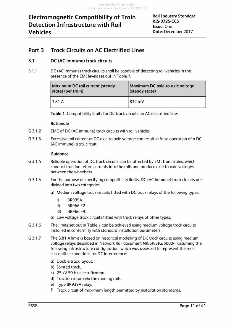
3.1.1 DC (AC immune) track circuits shall be capable of detecting rail vehicles in thepresence of the EMI levels set out in Table 1.
Maximum DC rail current (steadystate) (per train)
Maximum DC axle-to-axle voltage(steady state)
3.81 A 832 mV
Table 1: Compatibility limits for DC track circuits on AC electrified lines
Rationale
G 3.1.2 EMC of DC (AC immune) track circuits with rail vehicles.
G 3.1.3 Excessive rail current or DC axle-to axle-voltage can result in false operation of a DC(AC immune) track circuit.
Guidance
G 3.1.4 Reliable operation of DC track circuits can be affected by EMI from trains, whichconduct traction return currents into the rails and produce axle-to-axle voltagesbetween the wheelsets.
G 3.1.5 For the purpose of specifying compatibility limits, DC (AC immune) track circuits aredivided into two categories:
a) Medium voltage track circuits fitted with DC track relays of the following types:
i) BR939A.ii) BR966 F2.iii) BR966 F9.
b) Low voltage track circuits fitted with track relays of other types.
G 3.1.6 The limits set out in Table 1 can be achieved using medium voltage track circuitsinstalled in conformity with standard installation parameters.
G 3.1.7 The 3.81 A limit is based on historical modelling of DC track circuits using mediumvoltage relays described in Network Rail document NR/SP/SIG/50004, assuming thefollowing infrastructure configuration, which was assessed to represent the mostsusceptible conditions for DC interference:
a) Double track layout.b) Jointed track.c) 25 kV 50 Hz electrification.d) Traction return via the running rails.e) Type BR939A relay.f) Track circuit of maximum length permitted by installation standards.
Electromagnetic Compatibility of TrainDetection Infrastructure with RailVehicles
Rail Industry StandardRIS-0725-CCSIssue: OneDate: December 2017
RSSB Page 11 of 41
Uncontrolled when printed Document comes into force on 02/12/2017
G 3.1.8 The 832 mV limit is derived from the historical modelling in NR/SP/SIG/50004 basedon a track circuit fitted with a BR966 F2 relay, which was shown to be the mostsusceptible type of medium voltage DC track relay to axle-to-axle voltage with intactinfrastructure.
G 3.1.9 Both limits take into account transmitter breakthrough and an allowance for thepresence of other trains, and incorporate a 20% safety margin.
G 3.1.10 For the purpose of determining susceptibility to low frequency interference, theresponse of a DC track relay is considered to be represented by a compositefrequency response curve which can be modelled as a cascade of two single poleButterworth low pass filters with –3 dB points at 0.5 Hz and 4.14 Hz.
G 3.1.11 Further detail of the historical modelling is set out in NR/SP/SIG/50004. Thismodelling covers DC track circuits using both medium voltage and low voltage trackrelays. The infrastructure target for EMC susceptibility is based on the provision ofmedium voltage track circuits. Existing low voltage DC track circuits might not meetthese limits; if low voltage track circuits are modified, they would be limited to arestricted range of installation parameters in order to comply with these limits. Theinformation on low voltage DC track circuits in NR/SP/SIG/50004 may still beapplicable to assessing compatibility with existing track circuits of this type.
G 3.1.12 NR/SP/SIG/50004 identifies a lower maximum rail current limit of 1.18 A for DC (ACimmune) track circuits on a double track line, or 0.62 A on a single track line, allowingfor degraded infrastructure conditions, for example a break in a section of thetraction return circuit. Consideration of the impact of infrastructure failures on EMC ispart of the route compatibility assessment.
G 3.1.13 Under certain failure conditions, and in some atmospheric conditions such as thoseleading to a build-up of ice on the overhead line, there is a possibility that trainsmight exceed the maximum current limit, and the risk from false energisation of trackcircuits will need to be considered as part of the route compatibility assessment.
G 3.1.14 To assess the effect of DC transients produced by rolling stock, one approach is toundertake a comparative assessment with existing rolling stock operating on theroute.
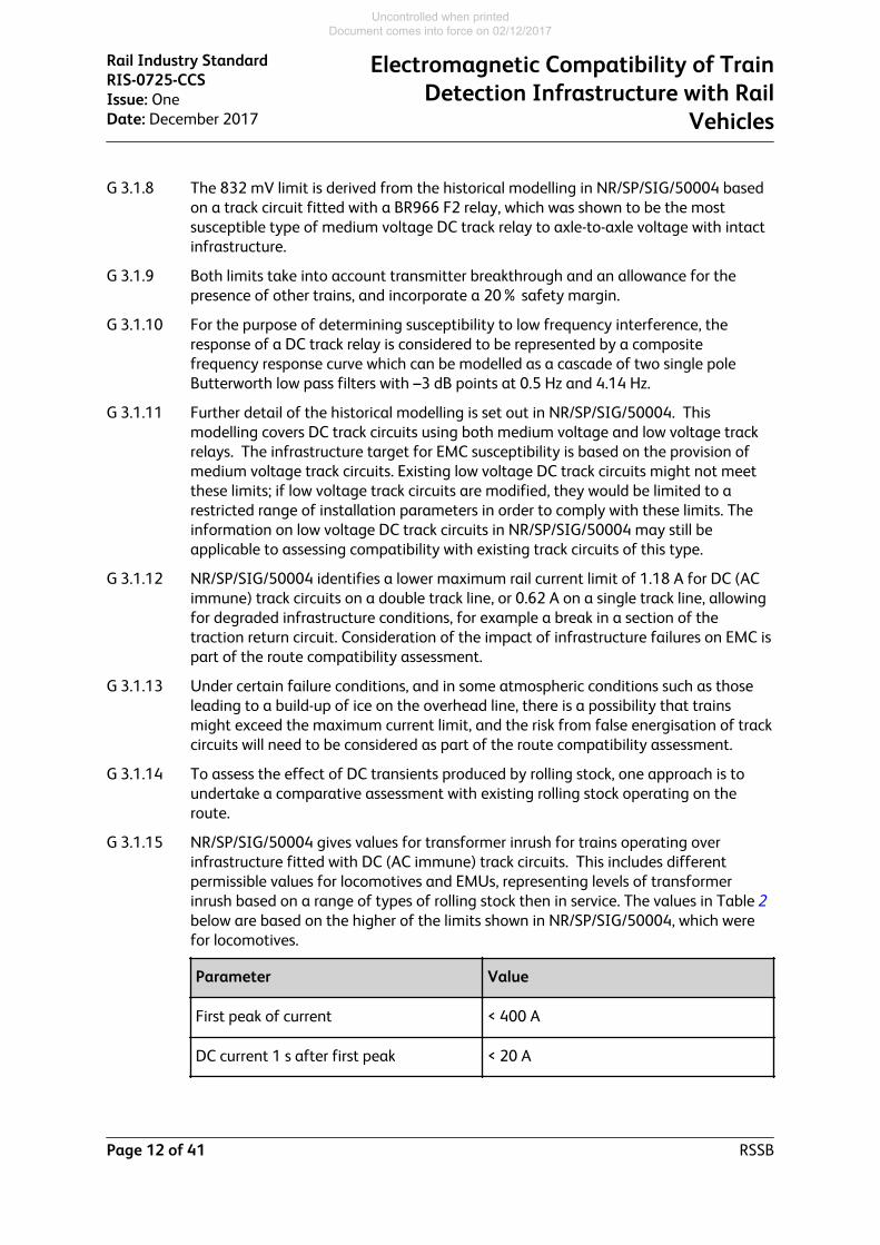
G 3.1.15 NR/SP/SIG/50004 gives values for transformer inrush for trains operating overinfrastructure fitted with DC (AC immune) track circuits. This includes differentpermissible values for locomotives and EMUs, representing levels of transformerinrush based on a range of types of rolling stock then in service. The values in Table 2below are based on the higher of the limits shown in NR/SP/SIG/50004, which werefor locomotives.
Parameter Value
First peak of current < 400 A
DC current 1 s after first peak < 20 A
Rail Industry StandardRIS-0725-CCSIssue: OneDate: December 2017
Electromagnetic Compatibility of TrainDetection Infrastructure with Rail
Vehicles
Page 12 of 41 RSSB
Uncontrolled when printed Document comes into force on 02/12/2017

Parameter Value
Interval between successive inrushtransients
> 5 s
Table 2: Transient current limits for DC track circuits
G 3.1.16 Where these values cannot be achieved, NR/SP/SIG/50004 provides guidance onusing a risk-based comparison against existing rolling stock that operates on theroute without showing evidence of transient interference to DC track circuits.
3.2 Reed track circuits (AC lines)
3.2.1 Reed track circuits on AC electrified lines shall be capable of detecting rail vehicles inthe presence of the EMI levels set out in Table 3.
Frequency Maximum steadystate rail current(per train)
Maximum steadystate axle-to-axlevoltageDesignation Hz
f211 363 90.2 mA 99 mV
f212 366
f213 369
f214 372
f215 375
f216 378
f217 381
f218 384
f219 408
f220 417
f221 423
Table 3: Compatibility limits for reed track circuits on AC electrified lines
3.2.2 Reed track circuits on AC electrified lines shall meet the values set out in Table 3 for ahalf-power (-3 dB) bandwidth of 0.5 Hz.
Electromagnetic Compatibility of TrainDetection Infrastructure with RailVehicles
Rail Industry StandardRIS-0725-CCSIssue: OneDate: December 2017
RSSB Page 13 of 41
Uncontrolled when printed Document comes into force on 02/12/2017

Rationale
G 3.2.3 EMC of reed track circuits with rail vehicles.
G 3.2.4 Excessive rail current or axle-to-axle voltage at reed frequencies can result in falseoperation of a reed track circuit.
G 3.2.5 Reed track circuits are susceptible to interference at their operating frequency, whichis a single unmodulated frequency determined by a narrow bandwidth mechanicalreed filter. The specified bandwidth criteria represent the frequency response of thereed track circuit receiver.
Guidance
G 3.2.6 Reliable operation of reed track circuits can be affected by EMI from trains, whichconduct traction return currents into the rails and produce axle-to-axle voltagesbetween the wheelsets.
G 3.2.7 The limits set out in Table 3 are based on historical modelling of a single rail reedtrack circuit in Network Rail document NR/SP/SIG/50002, which assumed thefollowing infrastructure configuration, assessed to represent the most susceptibleconditions to EMI for intact infrastructure:
a) Single track line.b) Reed track circuit in single rail mode.c) Most sensitive receiver setting.d) Maximum track circuit length 1200 m.
G 3.2.8 Further detail of the modelling of a single rail reed track circuit is set out inNR/SP/SIG/50002.
G 3.2.9 NR/SP/SIG/50002 identifies a lower maximum rail current limit of 82.5 mA fordegraded infrastructure conditions, for example a break in a section of the tractionreturn circuit. Consideration of the impact of infrastructure failures on EMC is part ofthe route compatibility assessment.
G 3.2.10 Further details of the frequency response of the reed track circuit receiver are set outin NR/SP/SIG/50002.
G 3.2.11 High-power variants of reed track circuits supply higher currents to the rail and areused in certain applications where a higher level of immunity is required. Theyincorporate an attenuator in the input to the receiver making them less susceptible toEMI than the standard type, and will therefore be compliant with the limits set out inTable 3.
3.3 TI 21 / EBI Track 200 (AC lines)
3.3.1 TI 21 / EBI Track 200 track circuits (AC lines) - rail current
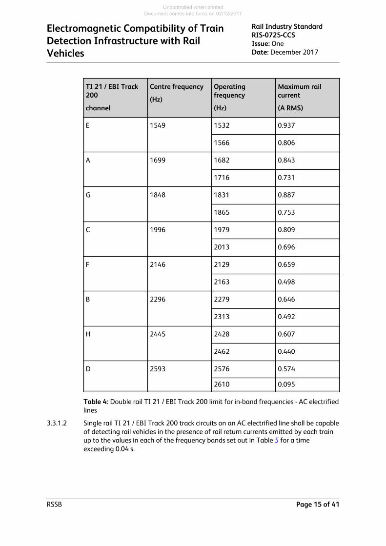
3.3.1.1 Double rail TI 21 / EBI Track 200 track circuits on an AC electrified line shall becapable of detecting rail vehicles in the presence of rail currents conducted by eachtrain up to the values in each of the frequency bands set out in Table 4, for a timeexceeding 0.04 s.
Rail Industry StandardRIS-0725-CCSIssue: OneDate: December 2017
Electromagnetic Compatibility of TrainDetection Infrastructure with Rail
Vehicles
Page 14 of 41 RSSB
Uncontrolled when printed Document comes into force on 02/12/2017
TI 21 / EBI Track200
channel
Centre frequency
(Hz)
Operatingfrequency
(Hz)
Maximum railcurrent
(A RMS)
E 1549 1532 0.937
1566 0.806
A 1699 1682 0.843
1716 0.731
G 1848 1831 0.887
1865 0.753
C 1996 1979 0.809
2013 0.696
F 2146 2129 0.659
2163 0.498
B 2296 2279 0.646
2313 0.492
H 2445 2428 0.607
2462 0.440
D 2593 2576 0.574
2610 0.095
Table 4: Double rail TI 21 / EBI Track 200 limit for in-band frequencies - AC electrifiedlines
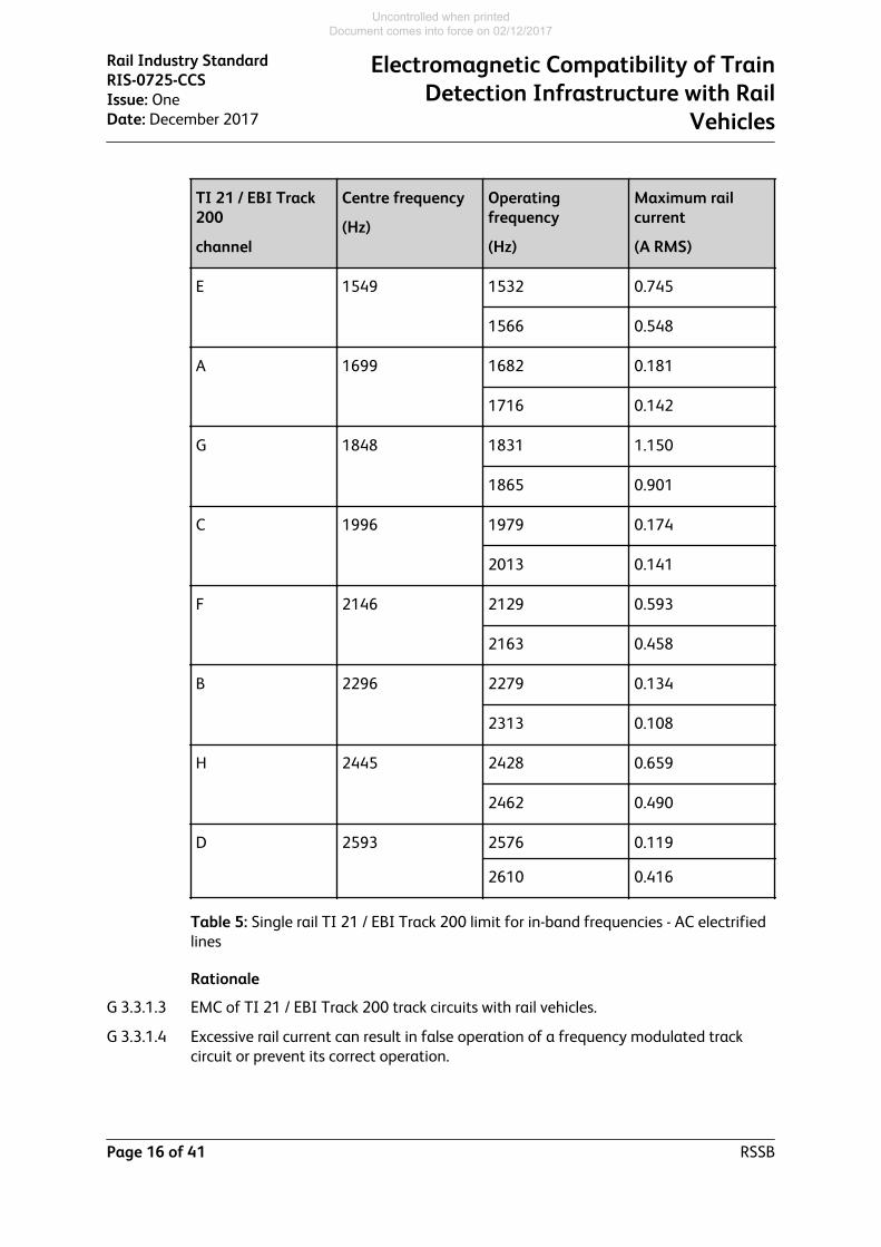
3.3.1.2 Single rail TI 21 / EBI Track 200 track circuits on an AC electrified line shall be capableof detecting rail vehicles in the presence of rail return currents emitted by each trainup to the values in each of the frequency bands set out in Table 5 for a timeexceeding 0.04 s.
Electromagnetic Compatibility of TrainDetection Infrastructure with RailVehicles
Rail Industry StandardRIS-0725-CCSIssue: OneDate: December 2017
RSSB Page 15 of 41
Uncontrolled when printed Document comes into force on 02/12/2017
TI 21 / EBI Track200
channel
Centre frequency
(Hz)
Operatingfrequency
(Hz)
Maximum railcurrent
(A RMS)
E 1549 1532 0.745
1566 0.548
A 1699 1682 0.181
1716 0.142
G 1848 1831 1.150
1865 0.901
C 1996 1979 0.174
2013 0.141
F 2146 2129 0.593
2163 0.458
B 2296 2279 0.134
2313 0.108
H 2445 2428 0.659
2462 0.490
D 2593 2576 0.119
2610 0.416
Table 5: Single rail TI 21 / EBI Track 200 limit for in-band frequencies - AC electrifiedlines
Rationale
G 3.3.1.3 EMC of TI 21 / EBI Track 200 track circuits with rail vehicles.
G 3.3.1.4 Excessive rail current can result in false operation of a frequency modulated trackcircuit or prevent its correct operation.
Rail Industry StandardRIS-0725-CCSIssue: OneDate: December 2017
Electromagnetic Compatibility of TrainDetection Infrastructure with Rail
Vehicles
Page 16 of 41 RSSB
Uncontrolled when printed Document comes into force on 02/12/2017

Guidance
G 3.3.1.5 Reliable operation of TI 21 / EBI Track 200 track circuits can be affected by EMI fromtrains which conduct currents within the track circuit operating frequency bands intothe rails.
G 3.3.1.6 The specified current levels and the minimum time of 0.04 s are relevant to a right-side failure of a track circuit (track circuit showing occupied when clear). To cause awrong-side failure (track circuit showing clear when occupied), current exceeding thespecified limit would have to be present for 2 s and be modulated at the correct rate(between 3.36 Hz and 6.24 Hz) between the two operating frequencies.
G 3.3.1.7 Experience suggests that TI 21 / EBI Track 200 track circuits fitted with digitalreceivers are immune to common transients, including:
a) Inrush current up to 300 A.b) Ice on the overhead line for line current of 300 A.c) Pantograph bounce with 300 A traction current.d) Circuit breaker opening with 300 A traction current.
G 3.3.1.8 The maximum current values set out in Table 4 and Table 5:
a) Are applicable to analogue and digital receivers.b) Include a 50% apportionment to allow for other interference sources.c) Are consistent with TS 50238-2:2015 section A.17, which includes only the lower
value for each channel, and supersede the data set out in Network Rail documentNR/GN/SIG/50008.
G 3.3.1.9 The maximum current values set out in Table 4 are based on the following modellingassumptions:
a) Maximum length 1100 m end fed or 2000 m centre fed.b) Cross-bonding in accordance with applicable Network Rail standards.c) Termination with either end termination units (ETUs) or tuning units (TUs).d) Worst case return traction current imbalance across an ETU/TU in a double rail
installation is 10%.e) B3 type impedance bonds.
G 3.3.1.10 The maximum current values set out in Table 5 are based on the following modellingassumptions:
a) Termination with either ETUs or track connection units (TCUs).b) Maximum length 250 m with ETU or 200 m with TCU.c) For configurations with ETUs, only frequencies A, B, C and D are used on single
track or two-track lines.d) Single rail track circuits using frequencies E, F, G and H on AC electrified lines are
limited in length to provide higher levels of immunity, as these frequencies areclose to odd harmonics of the 50 Hz traction supply and it is not practicable todesign AC traction to avoid significant currents at these frequencies.
Electromagnetic Compatibility of TrainDetection Infrastructure with RailVehicles
Rail Industry StandardRIS-0725-CCSIssue: OneDate: December 2017
RSSB Page 17 of 41
Uncontrolled when printed Document comes into force on 02/12/2017

3.3.2 TI 21 / EBI Track 200 track circuits - bandwidth
3.3.2.1 Assessment of conformity of TI 21 / EBI Track 200 track circuits on AC electrified lineswith the immunity limits set out in Table 4 and Table 5 shall be based on analysis oftrain emissions using a digital filter with a bandwidth of:
a) -3 dB at ± 6 Hz from centre frequency.b) -20 dB at ± 30 Hz from centre frequency.
Rationale
G 3.3.2.2 The specified parameters of the filter provide a frequency response that isrepresentative of the TI 21 and EBI Track 200 track circuit receivers.
Guidance
G 3.3.2.3 Train emissions are analysed using a defined filter characteristic for each of the TI21 / EBI Track 200 track circuit operating frequencies to provide an indication of thepredicted effect on the track circuit receivers.
G 3.3.2.4 Further details of the track circuit response are given in NR/GN/SIG/50008.
3.3.3 TI 21 / EBI Track 200 track circuits - immunity to 50 Hz harmonics
Guidance
G 3.3.3.1 Table 6 gives accepted limits for the susceptibility of TI 21 / EBI Track 200 trackcircuits to harmonics of 50 Hz mains frequencies. To assess train current against thesesusceptibility limits, the limit shown in the table for each 50 Hz harmonic can becompared with the root of sum of squares of the FFT of the traction current for allfrequency bins between the lower frequency and upper frequency identified in thetable, using a 1 Hz FFT with Hanning window and 50% overlap.
Channel 50 HzharmonicfrequencyHz
Harmonicorder
Lowerfrequencyforanalysis,Hz
Upperfrequencyforanalysis,Hz
DoubleRail pertrainlimit, A
SingleRail pertrainlimit, A
E 1500 30 1494 1506 6.351 6.212
1550 31 1543 1557 0.892 0.698
1600 32 1593 1607 6.916 2.531
A 1650 33 1643 1657 5.429 1.462
1700 34 1693 1707 0.805 0.178
1750 35 1743 1757 6.286 0.898
Rail Industry StandardRIS-0725-CCSIssue: OneDate: December 2017
Electromagnetic Compatibility of TrainDetection Infrastructure with Rail
Vehicles
Page 18 of 41 RSSB
Uncontrolled when printed Document comes into force on 02/12/2017

Channel 50 HzharmonicfrequencyHz
Harmonicorder
Lowerfrequencyforanalysis,Hz
Upperfrequencyforanalysis,Hz
DoubleRail pertrainlimit, A
SingleRail pertrainlimit, A
G 1800 36 1792 1808 4.791 7.380
1850 37 1842 1858 0.873 1.065
1900 38 1892 1908 6.621 4.436
C 1950 39 1942 1958 3.807 1.075
2000 40 1992 2008 0.805 0.151
2050 41 2041 2059 7.296 1.101
F 2100 42 2091 2109 3.165 3.309
2150 43 2141 2159 0.592 0.493
2200 44 2191 2209 3.945 3.077
B 2250 45 2241 2259 3.062 0.744
2300 46 2290 2310 0.585 0.111
2350 47 2340 2360 3.755 0.638
H 2400 48 2390 2410 2.383 3.058
2450 49 2440 2460 0.503 0.521
2500 50 2490 2510 3.465 3.154
D 2550 51 2539 2561 1.630 0.480
2600 52 2589 2611 0.416 0.094
2650 53 2639 2661 4.699 0.783
Table 6: TI 21 / EBI Track 200 limits for mains harmonic frequencies
G 3.3.3.2 The analysis specified above will not resolve short duration exceedances. Exceedancesof these limits for longer than 1 s may lead to a right-side failure (track circuit
Electromagnetic Compatibility of TrainDetection Infrastructure with RailVehicles
Rail Industry StandardRIS-0725-CCSIssue: OneDate: December 2017
RSSB Page 19 of 41
Uncontrolled when printed Document comes into force on 02/12/2017

showing occupied when clear), but digital receivers have been proved to be immuneto certain types of transient as stated in G 3.3.1.7.
3.3.4 TI 21 / EBI Track 200 track circuits - axle-to-axle voltage
3.3.4.1 Double rail TI 21 and EBI Track 200 track circuits on an AC electrified line shall becapable of detecting rail vehicles in the presence of axle-to-axle voltages introducedby each train up to 0.151 V in each of the frequency bands set out in Table 4.
3.3.4.2 Single rail TI 21 and EBI Track 200 track circuits on an AC electrified line shall becapable of detecting rail vehicles in the presence of axle-to-axle voltages introducedby each train up to 0.120 V in each of the frequency bands set out in Table 5.
Rationale
G 3.3.4.3 Excessive axle-to-axle voltages can result in false operation of a frequency modulatedtrack circuit.
G 3.3.4.4 These limits are based on analysis of TI 21 / EBI Track 200 track circuits usingfrequencies A to D on a double track line.
Guidance
G 3.3.4.5 The limits are derived from analysis of a right-side failure scenario in which aninterference voltage introduced into an unoccupied track section by a train onanother section of track prevents energisation of the TI 21 / EBI Track 200 receiver,causing the track circuit to be shown as occupied. To cause a wrong-side failure (trackcircuit showing clear when occupied), an interference voltage would have to bepresent for at least 2 s and modulated at the correct rate between the two operatingfrequencies.
G 3.3.4.6 Frequencies E to H are only used where there are more than two tracks, and theadditional parallel current paths available in this case means that immunity tolongitudinal voltage will be higher than on a double track line.
Rail Industry StandardRIS-0725-CCSIssue: OneDate: December 2017
Electromagnetic Compatibility of TrainDetection Infrastructure with Rail
Vehicles
Page 20 of 41 RSSB
Uncontrolled when printed Document comes into force on 02/12/2017

Part 4 Track Circuits on DC Electrified Lines
4.1 50 Hz track circuits
4.1.1 50 Hz AC track circuits - steady state
4.1.1.1 50 Hz AC track circuits shall be capable of detecting rail vehicles in the presence ofthe levels of steady state EMI set out in Table 7, over the frequency range 48 Hz to52 Hz.
Track circuitconfiguration
Maximum rail current(steady state) (per train)
Maximum axle-to-axlevoltage (steady state)
Single rail 1.98 A 150 mV
Double rail 4.0 A Not defined
Table 7: Compatibility limits for 50 Hz AC track circuits on DC electrified lines
Rationale
G 4.1.1.2 EMC of 50 Hz AC track circuits with rail vehicles.
G 4.1.1.3 Excessive rail current or AC axle-to-axle voltage can result in false operation of a50 Hz AC track circuit.
G 4.1.1.4 The frequency range of 48 Hz to 52 Hz allows for variation in the frequency of themains supply, which would allow the track relay to respond to interference voltages atthese frequencies.
G 4.1.1.5 The limits represent one-third of the current that could operate a track relay, allowingfor transmitter breakthrough and the presence of other trains.
Guidance
G 4.1.1.6 Reliable operation of 50 Hz AC track circuits can be adversely affected by EMI fromtrains, which conduct traction return currents into the rails and produce axle-to-axlevoltages between the wheelsets. This can include loss of detection of a rail vehicle.
G 4.1.1.7
G 4.1.1.8 The operation of 50 Hz AC track circuits is also affected by the level of 50 Hz tractionsupply ripple voltage that can be conducted by the train. Recent EMC assessmentshave been made on the basis of a figure of 0.6 V RMS for traction supply ripple.
G 4.1.1.9 The limits for single rail track circuits set out in Table 7 are based on historicalmodelling described in Network Rail document NR/GN/SIG/50005, which assumedthe following infrastructure configuration, representing the most susceptibleconditions to EMI for intact infrastructure:
a) 750 V DC electrification.b) Maximum length of single-rail 50 Hz track circuit is 200 m (although the limit may
still be applicable to longer track circuits with additional cross-bonding).
Electromagnetic Compatibility of TrainDetection Infrastructure with RailVehicles
Rail Industry StandardRIS-0725-CCSIssue: OneDate: December 2017
RSSB Page 21 of 41
Uncontrolled when printed Document comes into force on 02/12/2017

c) Relay types - VT1, CE391 and G4.
G 4.1.1.10 The VT1(SP) configuration of 50 Hz track circuit uses a VT1 relay, but the installationand configuration was designed to offer greater immunity to higher levels of tractioncurrent.
G 4.1.1.11 The limits for double rail track circuits set out in Table 7 are based on historicalmodelling described in Network Rail document NR/SP/SIG/50006, which assumed thefollowing infrastructure configuration, representing the most susceptible conditionsto EMI for intact infrastructure:
a) 750 V DC electrification.b) Maximum length of double-rail 50 Hz track circuit 1000 m (although the limit may
still be applicable to longer track circuits with additional cross-bonding).c) Maximum length of traction feeder section between substations 7.5 km.d) Relay types - VT1, CE391 and G4.
G 4.1.1.12 Further detail of the modelling of AC 50 Hz track circuits is set out in Network Raildocuments NR/GN/SIG/50005 and NR/SP/SIG/50006.
4.1.2 50 Hz AC track circuits - transients
Guidance
G 4.1.2.1 Transient currents passing into the rails can contain sufficient 50 Hz components toenergise a 50 Hz track relay for a short period of time.
G 4.1.2.2 It is not practicable to specify a network-wide limit for transient 50 Hz interference. Asingle transient event is unlikely to energise a track relay for long enough to create arisk from incorrect clearance. However, in many cases (for example in conditions ofintermittent contact between collector shoe and traction rail) transients can occurwith sufficient regularity that a sequence of transients may be capable of energisingthe track relay for sufficient time to create a risk.
G 4.1.2.3 It is good practice to incorporate a time delay in the interface between 50 Hz trackcircuits and the interlocking to mitigate the effect of transients. Methods of achievingthis include provision of a slow to operate follower relay or using an interlocking inputthat includes an inherent time delay.
G 4.1.2.4 The design of the traction current collection and control limits 50 Hz transients andreduces their effect on 50 Hz track circuits. Good practice in this area includes thefollowing features:
a) The train shoe gear connected together by cables to form shoebuses.b) Each shoebus fed by at least two shoes per train side.c) Each shoebus to span the outer bogies of at least 2 x 20 m cars.d) Maximum DC current per shoebus 3500 A for normal (undegraded) operation.e) Line current controlled so that no change in tractive or braking effort results in a
di/dt greater than that caused by gaps.
G 4.1.2.5 In the presence of infrastructure faults such as a broken rail, the susceptibility of 50Hz track circuits is increased considerably, and absolute values of allowable 50 Hzcurrents would be unrealistically low. It is therefore not practicable to specify a
Rail Industry StandardRIS-0725-CCSIssue: OneDate: December 2017
Electromagnetic Compatibility of TrainDetection Infrastructure with Rail
Vehicles
Page 22 of 41 RSSB
Uncontrolled when printed Document comes into force on 02/12/2017

network-wide limit for degraded infrastructure conditions. EMC between 50 Hz trackcircuits and rail vehicles in foreseeable degraded conditions is assessed as part of theroute compatibility assessment.
4.2 Reed track circuits (DC lines)
4.2.1 Reed track circuits on DC electrified lines shall be capable of detecting rail vehicles inthe presence of the EMI levels set out in Table 8.
Frequency Maximum steadystate rail current(per train)
Maximum steadystate axle-to-axlevoltageDesignation Hz
f211 363 195 mA 146 mV
f212 366
f213 369
f214 372
f215 375
f216 378
f217 381
f218 384
f219 408
f220 417
f221 423
Table 8: Compatibility limits for reed track circuits on DC electrified lines
4.2.2 Reed track circuits on DC electrified lines shall meet the values set out in Table 8 for ahalf-power (-3 dB) bandwidth of 0.5 Hz.
Rationale
G 4.2.3 EMC of reed track circuits with rail vehicles.
G 4.2.4 Excessive rail current or axle-to-axle voltage can result in false operation of a reedtrack circuit.
G 4.2.5 Reed track circuits are susceptible to interference at their operating frequency, whichis a single unmodulated frequency determined by a narrow bandwidth mechanical
Electromagnetic Compatibility of TrainDetection Infrastructure with RailVehicles
Rail Industry StandardRIS-0725-CCSIssue: OneDate: December 2017
RSSB Page 23 of 41
Uncontrolled when printed Document comes into force on 02/12/2017
reed filter. The specified bandwidth criteria represent the frequency response of thereed track circuit receiver.
Guidance
G 4.2.6 Reliable operation of reed track circuits can be affected by EMI from trains, whichconduct traction return currents into the rails and produce axle-to-axle voltagesbetween the wheelsets.
G 4.2.7 The limits set out in Table 8 are based on the historical modelling of a double rail reedtrack circuit assuming the following infrastructure configuration, which was assessedto represent the most susceptible conditions to EMI for intact infrastructure:
a) Reed track circuit in double rail mode.b) DC electrified line.c) Double track line.d) Most sensitive receiver setting.e) Maximum track circuit length 1200 m.
G 4.2.8 Further detail of the modelling is set out in Network Rail document NR/SP/SIG/50003.
G 4.2.9 Further details of the frequency response of the reed track circuit receiver are set outin Network Rail document NR/SP/SIG/50002.
G 4.2.10 NR/SP/SIG/50003 identifies a lower maximum rail current limit of 96 mA for reedtrack circuits on DC electrified lines, to allow for degraded infrastructure conditions.Consideration of the impact of infrastructure failures on EMC is part of the routecompatibility assessment.
G 4.2.11 The analysis in NR/SP/SIG/50003 showed that the interference current limit for reedtrack circuit intermediate loop receivers in a worst case condition of infrastructuredefects is 88 mA.
4.3 TI 21 / EBI Track 200 (DC lines)
4.3.1 TI 21 / EBI Track 200 track circuits (DC lines) - rail current
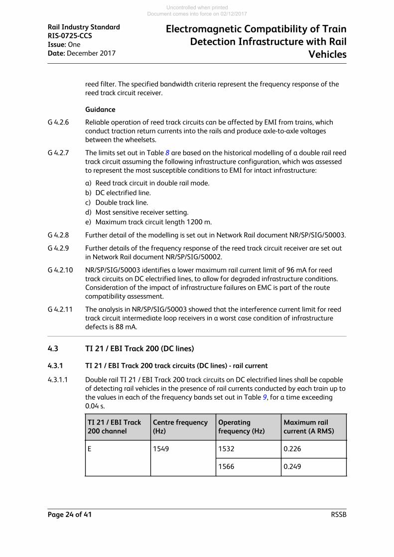
4.3.1.1 Double rail TI 21 / EBI Track 200 track circuits on DC electrified lines shall be capableof detecting rail vehicles in the presence of rail currents conducted by each train up tothe values in each of the frequency bands set out in Table 9, for a time exceeding0.04 s.
TI 21 / EBI Track200 channel
Centre frequency(Hz)
Operatingfrequency (Hz)
Maximum railcurrent (A RMS)
E 1549 1532 0.226
1566 0.249
Rail Industry StandardRIS-0725-CCSIssue: OneDate: December 2017
Electromagnetic Compatibility of TrainDetection Infrastructure with Rail
Vehicles
Page 24 of 41 RSSB
Uncontrolled when printed Document comes into force on 02/12/2017

TI 21 / EBI Track200 channel
Centre frequency(Hz)
Operatingfrequency (Hz)
Maximum railcurrent (A RMS)
A 1699 1682 0.178
1716 0.202
G 1848 1831 0.189
1865 0.219
C 1996 1979 0.157
2013 0.182
F 2146 2129 0.228
2163 0.262
B 2296 2279 0.237
2313 0.264
H 2445 2428 0.225
2462 0.247
D 2593 2576 0.23
2610 0.264
Table 9: TI 21 / EBI Track 200 double rail or single rail limit for in-band frequencies -DC electrified lines
Rationale
G 4.3.1.2 EMC of TI 21 / EBI Track 200 track circuits with rail vehicles.
G 4.3.1.3 Excessive rail current can result in false operation of a frequency modulated trackcircuit.
Guidance
G 4.3.1.4 Reliable operation of TI 21 / EBI Track 200 track circuits can be affected by EMI fromtrains, which conduct currents within the track circuit operating frequency bands intothe rails.
G 4.3.1.5 The specified current levels and minimum time of 0.04 s are relevant to a right-sidefailure of a track circuit (track circuit showing occupied when clear). To cause awrong-side failure (track circuit showing clear when occupied), current exceeding the
Electromagnetic Compatibility of TrainDetection Infrastructure with RailVehicles
Rail Industry StandardRIS-0725-CCSIssue: OneDate: December 2017
RSSB Page 25 of 41
Uncontrolled when printed Document comes into force on 02/12/2017

specified limit would have to be present for 2 s and be modulated at the correct ratebetween the two operating frequencies.
G 4.3.1.6 The maximum current values set out in Table 9:
a) Are applicable to analogue and digital receivers.b) Are consistent with TS 50238-2:2015 section A.17 (although this includes only the
lower value for each channel), and supersede the data set out in in Network Raildocument NR/GN/SIG/50008.
G 4.3.1.7 The maximum current values set out in Table 9 are based on historical modellingassuming the following infrastructure configuration:
a) Maximum length 1100 m end fed or 2000 m centre fed.b) Cross-bonding in accordance with applicable Network Rail standards.c) Termination with either ETUs or TUs.d) Worst case return traction current imbalance (100%) across an ETU/TU in a
double rail installation.
4.3.2 TI 21 / EBI Track 200 track circuits -bandwidth
4.3.2.1 Assessment of conformity of TI 21 / EBI Track 200 track circuits on DC electrified lineswith the emission limits set out in Table 9 shall be based on analysis of trainemissions using a digital filter with a bandwidth of:
a) -3 dB at ± 6 Hz from centre frequency.b) -20 dB at ± 30 Hz from centre frequency.
Rationale
G 4.3.2.2 The specified parameters of the filter provide a frequency response that isrepresentative of the TI 21 and EBI Track 200 track circuit receivers.
Guidance
G 4.3.2.3 Train emissions are analysed using a defined filter characteristic for each of the TI21 / EBI Track 200 track circuit operating frequencies to provide an indication of thepredicted effect on the track circuit receivers.
G 4.3.2.4 Further details of the track circuit response are given in Network Rail documentNR/GN/SIG/50008.
4.4 FS2600 track circuits
4.4.1 FS2600 track circuits shall be capable of detecting rail vehicles in the presence of theEMI levels set out in Table 10 at the operating frequencies set out in Table 11.
Rail current (per train) Axle-to-axle voltage
472 mA 369 mV
Table 10: Compatibility limits for FS2600 track circuits on DC electrified lines
Rail Industry StandardRIS-0725-CCSIssue: OneDate: December 2017
Electromagnetic Compatibility of TrainDetection Infrastructure with Rail
Vehicles
Page 26 of 41 RSSB
Uncontrolled when printed Document comes into force on 02/12/2017

Channel no. Centre (carrier)frequency (Hz)
Lower frequency(Hz)
Upper frequency(Hz)
1 388.8 371.8 405.8
2 403.2 386.2 420.2
3 417.6 400.6 434.6
4 432.0 415.0 449.0
5 441.6 424.6 458.6
6 456.0 439.0 473.0
7 470.4 453.4 487.4
8 484.8 467.8 501.8
9 494.4 477.4 511.4
10 508.8 491.8 525.8
Table 11: FS2600 operating frequencies
Rationale
G 4.4.2 EMC of FS2600 track circuits with rail vehicles.
G 4.4.3 Excessive rail current or axle-to-axle voltage can result in false operation of a FS2600track circuit.
Guidance
G 4.4.4 FS2600 track circuit receivers respond only to a correctly coded signal carrying a validpair of frequencies. For an interference signal to falsely energise an FS2600 receiver,leading to loss of detection when the section is occupied, the signal has to be presentfor at least 944 ms and correctly coded. It is unlikely that train-generatedinterference will produce a correctly coded signal; however, a signal in the frequencyrange of the receiver which does not have correct coding can cause a right-side failure(de-energisation of a receiver in an adjacent track section which is not occupied by atrain).
G 4.4.5 The digital sampling process of the FS2600 receiver analyses the received signal inbands of 4.8 Hz, and therefore responds to a signal within 2.4 Hz of the nominalfrequency.
G 4.4.6 The limits set out in Table 10 are based on the historical modelling of an FS2600track circuit, which assumed the following infrastructure configuration, which
Electromagnetic Compatibility of TrainDetection Infrastructure with RailVehicles
Rail Industry StandardRIS-0725-CCSIssue: OneDate: December 2017
RSSB Page 27 of 41
Uncontrolled when printed Document comes into force on 02/12/2017
represents the most susceptible conditions to EMI with effectively bondedinfrastructure:
a) Double track.b) Jointed track.c) 750 V DC third rail electrification.d) Traction return via running rails.e) Track circuit maximum length 1200 m.f) Track circuit installed in double rail mode.g) Train occupying FS2600 track circuit channel 10 (508.8 Hz); the adjacent track
circuit is channel 1.h) Track circuit receiver at highest gain setting.i) Train interference limit for intact infrastructure is one-third of total interference
budget.
G 4.4.7 Further detail of the modelling is set out in Network Rail document NR/GN/SIG/50009.
Rail Industry StandardRIS-0725-CCSIssue: OneDate: December 2017
Electromagnetic Compatibility of TrainDetection Infrastructure with Rail
Vehicles
Page 28 of 41 RSSB
Uncontrolled when printed Document comes into force on 02/12/2017

Part 5 Track Circuits Used on Both AC and DC Electrified Lines
5.1 EBI Track 400
5.1.1 EBI Track 400 track circuits - rail current
5.1.1.1 EBI Track 400 ‘open line’ track circuits shall be capable of detecting rail vehicles inthe presence of rail currents conducted by each train up to the values at each of thefrequencies set out in Table 12.
Channel Centre frequency(Hz)
Maximum rail current (steady state) (ARMS)
Double rail Single rail
E 1549 0.953 0.098 #
A 1699 0.936 0.099
G 1848 0.81 0.091 #
C 1996 0.778 0.087
F 2146 0.663 0.072 #
B 2296 0.628 0.069
H 2445 0.545 0.061 #
D 2593 0.547 0.063
Table 12: EBI Track 400 mainline (open line) - worst case centre frequencyinterference limit
# Note: frequencies E, F, G and H are not currently used in single rail form on ACelectrified lines because these frequencies are close to odd harmonics of the 50 Hzsupply.
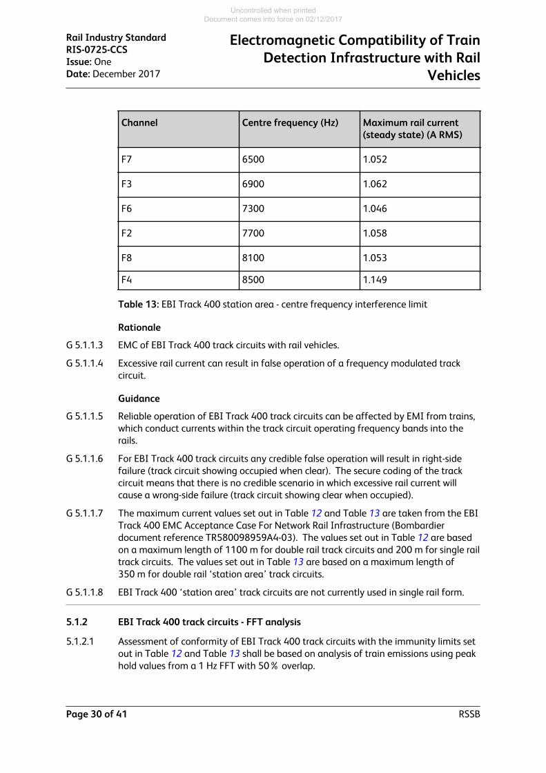
5.1.1.2 EBI Track 400 ‘station area’ double rail track circuits shall be capable of detecting therail vehicles in the presence of rail currents conducted by each train up to the valuesat each of the frequencies set out in Table 13.
Channel Centre frequency (Hz) Maximum rail current(steady state) (A RMS)
F5 5700 1.081
F1 6100 1.073
Electromagnetic Compatibility of TrainDetection Infrastructure with RailVehicles
Rail Industry StandardRIS-0725-CCSIssue: OneDate: December 2017
RSSB Page 29 of 41
Uncontrolled when printed Document comes into force on 02/12/2017
Channel Centre frequency (Hz) Maximum rail current(steady state) (A RMS)
F7 6500 1.052
F3 6900 1.062
F6 7300 1.046
F2 7700 1.058
F8 8100 1.053
F4 8500 1.149
Table 13: EBI Track 400 station area - centre frequency interference limit
Rationale
G 5.1.1.3 EMC of EBI Track 400 track circuits with rail vehicles.
G 5.1.1.4 Excessive rail current can result in false operation of a frequency modulated trackcircuit.
Guidance
G 5.1.1.5 Reliable operation of EBI Track 400 track circuits can be affected by EMI from trains,which conduct currents within the track circuit operating frequency bands into therails.
G 5.1.1.6 For EBI Track 400 track circuits any credible false operation will result in right-sidefailure (track circuit showing occupied when clear). The secure coding of the trackcircuit means that there is no credible scenario in which excessive rail current willcause a wrong-side failure (track circuit showing clear when occupied).
G 5.1.1.7 The maximum current values set out in Table 12 and Table 13 are taken from the EBITrack 400 EMC Acceptance Case For Network Rail Infrastructure (Bombardierdocument reference TR580098959A4-03). The values set out in Table 12 are basedon a maximum length of 1100 m for double rail track circuits and 200 m for single railtrack circuits. The values set out in Table 13 are based on a maximum length of350 m for double rail ‘station area’ track circuits.
G 5.1.1.8 EBI Track 400 ‘station area’ track circuits are not currently used in single rail form.
5.1.2 EBI Track 400 track circuits - FFT analysis
5.1.2.1 Assessment of conformity of EBI Track 400 track circuits with the immunity limits setout in Table 12 and Table 13 shall be based on analysis of train emissions using peakhold values from a 1 Hz FFT with 50% overlap.
Rail Industry StandardRIS-0725-CCSIssue: OneDate: December 2017
Electromagnetic Compatibility of TrainDetection Infrastructure with Rail
Vehicles
Page 30 of 41 RSSB
Uncontrolled when printed Document comes into force on 02/12/2017

Rationale
G 5.1.2.2 The specified parameters for the digital filter used in the FFT analysis represent thefrequency response of the EBI Track 400 track circuit receivers.
Guidance
G 5.1.2.3 Train emissions are analysed using a defined filter characteristic for each of the EBITrack 400 track circuit operating frequencies to provide an indication of the predictedeffect on the track circuit receivers.
G 5.1.2.4 The FFT output is compared bin by bin with the frequency response curves of EBITrack 400 track circuits shown in Figure 1 and Figure 2, scaled for the specific trackcircuit using the frequencies and levels defined in Table 12 and Table 13.
Figure 1: Normalised frequency response curve of EBI Track 400 'open line' trackcircuit
Electromagnetic Compatibility of TrainDetection Infrastructure with RailVehicles
Rail Industry StandardRIS-0725-CCSIssue: OneDate: December 2017
RSSB Page 31 of 41
Uncontrolled when printed Document comes into force on 02/12/2017

Figure 2: Normalised frequency response curve of EBI Track 400 'station area' trackcircuit
5.1.3 EBI Track 400 track circuits - axle-to-axle voltage
Guidance
G 5.1.3.1 Accepted limits for longitudinal (axle-to-axle) voltage for EBI Track 400 Open Linetrack circuits are shown in Table 14 and Table 15.
G 5.1.3.2 These limits only cover channels A-D because it is expected that these will be themost vulnerable to longitudinal voltage due to their use on double track lines. If thesame values are used for channels E-H in multiple track areas they will be pessimistic.
Frequency channelof the victim trackcircuit
Channel of thetrack circuit withtrain generatingVaa
Frequencyspectrum, Hz
Double Rail Vaalimit, V with 50%margin
A C or D 1699 ± 5 0.607
B C or D 1996 ± 5 0.634
C A or B 2296 ± 5 0.577
D A or B 2593 ± 5 0.525
Table 14: EBI Track 400 Open Line: axle-to-axle voltage (Vaa) limits for victim doublerail track circuit, the adjacent track also fitted with double rail EBI Track 400 OpenLine
Rail Industry StandardRIS-0725-CCSIssue: OneDate: December 2017
Electromagnetic Compatibility of TrainDetection Infrastructure with Rail
Vehicles
Page 32 of 41 RSSB
Uncontrolled when printed Document comes into force on 02/12/2017

Frequency channel Frequencyspectrum, Hz
Double Rail Vaalimit, V with 50%margin
Single Rail Vaalimit, V with 50%margin
A 1699 ± 5 0.591 0.110
B 1996 ± 5 0.621 0.123
C 2296 ± 5 0.568 0.098
D 2593 ± 5 0.518 0092
Table 15: EBI Track 400 Open Line: axle-to-axle voltage (Vaa) limits for victim singlerail and double rail circuit, the adjacent track with any other track circuit
G 5.1.3.3 Accepted limits for longitudinal (axle-to-axle) voltage for EBI Track 400 Station Areatrack circuits are shown in Table 16 and Table 17.
Frequency channelof the victim trackcircuit
Channel of thetrack circuit withtrain generatingVaa
Frequencyspectrum, Hz
Double Rail Vaalimit, V with 50%margin
F1 F5 or F6 6100 ± 40 1.535
F2 F5 or F6 7700 ± 40 1.924
F5 F1 or F2 5700 ± 40 1.440
F6 F1 or F2 7300 ± 408 1.807
Table 16: EBI Track 400 Station Area: axle-to-axle voltage (Vaa) limits for victimdouble rail track circuit, the adjacent track also fitted with double rail EBI Track 400Station Area
Frequency channel Frequency spectrum, Hz Double Rail Vaa limit, Vwith 50% margin
F1 6100 ± 40 1.532
F2 7700 ± 40 1.921
F5 5700 ± 40 1.722
Electromagnetic Compatibility of TrainDetection Infrastructure with RailVehicles
Rail Industry StandardRIS-0725-CCSIssue: OneDate: December 2017
RSSB Page 33 of 41
Uncontrolled when printed Document comes into force on 02/12/2017

Frequency channel Frequency spectrum, Hz Double Rail Vaa limit, Vwith 50% margin
F6 7300 ± 408 2.332
Table 17: EBI Track 400 Station Area: axle-to-axle voltage (Vaa) limits for victimsingle rail and double rail track circuit, the adjacent track with any other track circuit
5.2 HVI track circuits
Guidance
G 5.2.1 Asymmetric current impulses of sufficient magnitude could energise an HVI trackcircuit relay when a train is occupying the track section.
G 5.2.2 Due to the nature of the waveform used by the HVI track circuits, the susceptibilitycriteria for compatibility cannot be expressed as a simple emission level at aparticular frequency or range of frequencies.
G 5.2.3 NR/GN/SIG/50007, section 5.4, sets out parameters of asymmetric waveforms asselection criteria to identify waveforms contained in train emissions that should beanalysed in detail to assess compatibility (for example by inputting them into anappropriate model), but these are not specified as actual operating limits.
G 5.2.4 The characteristics identified in NR/GN/SIG/50007 are:
a) di/dt exceeding 114 A/ms measured between samples 800 µs apart.b) Asymmetry > 0.1, where asymmetry is defined as ABS[(I+ + I-)/(I+ – I-)], I+ and I-
are the local maximum and minimum of the current waveform within 100 ms ofthe point of maximum di/dt.
G 5.2.5 There is no specified limit on axle-to-axle voltage for HVI track circuits as they are notsusceptible to realistically expected levels of axle-to-axle voltage.
Rail Industry StandardRIS-0725-CCSIssue: OneDate: December 2017
Electromagnetic Compatibility of TrainDetection Infrastructure with Rail
Vehicles
Page 34 of 41 RSSB
Uncontrolled when printed Document comes into force on 02/12/2017
Part 6 Track Circuits on Non-Electrified Lines
6.1 Track circuits used on non-electrified lines
Guidance
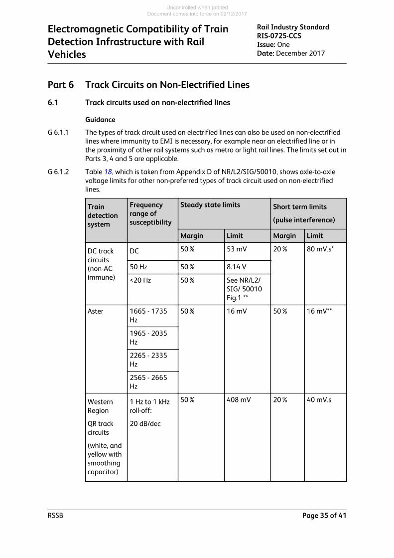
G 6.1.1 The types of track circuit used on electrified lines can also be used on non-electrifiedlines where immunity to EMI is necessary, for example near an electrified line or inthe proximity of other rail systems such as metro or light rail lines. The limits set out inParts 3, 4 and 5 are applicable.
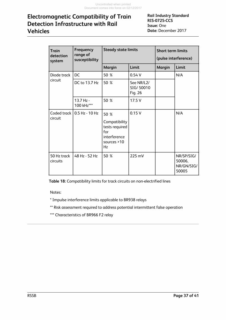
G 6.1.2 Table 18, which is taken from Appendix D of NR/L2/SIG/50010, shows axle-to-axlevoltage limits for other non-preferred types of track circuit used on non-electrifiedlines.
Traindetectionsystem
Frequencyrange ofsusceptibility
Steady state limits Short term limits
(pulse interference)
Margin Limit Margin Limit
DC trackcircuits(non-ACimmune)
DC 50% 53 mV 20% 80 mV.s*
50 Hz 50% 8.14 V
<20 Hz 50% See NR/L2/SIG/ 50010Fig.1 **
Aster 1665 - 1735Hz
50% 16 mV 50% 16 mV**
1965 - 2035Hz
2265 - 2335Hz
2565 - 2665Hz
WesternRegion
QR trackcircuits
(white, andyellow withsmoothingcapacitor)
1 Hz to 1 kHzroll-off:
20 dB/dec
50% 408 mV 20% 40 mV.s
Electromagnetic Compatibility of TrainDetection Infrastructure with RailVehicles
Rail Industry StandardRIS-0725-CCSIssue: OneDate: December 2017
RSSB Page 35 of 41
Uncontrolled when printed Document comes into force on 02/12/2017

Traindetectionsystem
Frequencyrange ofsusceptibility
Steady state limits Short term limits
(pulse interference)
Margin Limit Margin Limit
WesternRegion
QR trackcircuits
(blue)
1 Hz to 5 kHzroll-off:
5 dB/dec
50% 559 mV 20% 40 mV.s
WesternRegion
QR trackcircuits
(yellow, nosmoothingcapacitor)
1 Hz to 8 kHzroll-off:
5 dB/dec
50% 702 mV 20% 20 mV.s
Lucas >20 kHz N/A Compatibilitytests requiredforinterferencesourceshigher than10 V rms
N/A DC pulsewithrepetitiverate > 1kHz:0.028 V.s
ReedJointlesstrackcircuits
363 Hz -423 Hz
50% 201 mV See NR/L2/SIG/ 50010Fig. 18:
> 1 sduration100 mV.s *
Overlaytrackcircuits
5 kHz -100 kHz
N/A
50% ofapplied axle-to-axlevoltageresults ininterferencevoltage bydefinition
1.92 V Note ** for< 1 sduration
> 1 sduration:100 mV.s *
Rail Industry StandardRIS-0725-CCSIssue: OneDate: December 2017
Electromagnetic Compatibility of TrainDetection Infrastructure with Rail
Vehicles
Page 36 of 41 RSSB
Uncontrolled when printed Document comes into force on 02/12/2017
Traindetectionsystem
Frequencyrange ofsusceptibility
Steady state limits Short term limits
(pulse interference)
Margin Limit Margin Limit
Diode trackcircuit
DC 50 % 0.54 V N/A
DC to 13.7 Hz 50 % See NR/L2/SIG/ 50010Fig. 26
13.7 Hz -100 kHz***
50 % 17.5 V
Coded trackcircuit
0.5 Hz - 10 Hz 50 %
Compatibilitytests requiredforinterferencesources >10Hz
0.15 V N/A
50 Hz trackcircuits
48 Hz - 52 Hz 50 % 225 mV NR/SP/SIG/50006,NR/GN/SIG/50005
Table 18: Compatibility limits for track circuits on non-electrified lines
Notes:
* Impulse interference limits applicable to BR938 relays
** Risk assessment required to address potential intermittent false operation
*** Characteristics of BR966 F2 relay
Electromagnetic Compatibility of TrainDetection Infrastructure with RailVehicles
Rail Industry StandardRIS-0725-CCSIssue: OneDate: December 2017
RSSB Page 37 of 41
Uncontrolled when printed Document comes into force on 02/12/2017
Definitions
AC Alternating Current.
Axle Counter System A type of train detection system in which track-mountedequipment counts axles entering and leaving a track section ateach extremity. This information is evaluated to determinewhether the track section is occupied or clear.
Axle-to-axle voltage Voltage generated by a train and appearing between any twoaxles of the train
CCT Control-Command and Signalling (CCS) trackside subsystem.
DC Direct Current.
Double rail track circuit A track circuit where both rails are electrically separated from theadjacent track circuit, either using insulated rail joints or a tunedzone
ElectromagneticCompatibility (EMC)
The ability of equipment or a system to function satisfactorily in itselectromagnetic environment without introducing intolerableelectromagnetic disturbances to anything in that environment.
ETU (TI 21 / EBI Track track circuit) End termination unit.
Fast Fourier Transform(FFT)
An algorithm used in signal processing to convert a signal fromtime domain to frequency domain.
HVI High voltage impulse (type of track circuit).
Line current The current drawn by a train from the traction supply and returnedfrom the train into the rails. Where current is returned to the rails atmore than one point, this is the vector sum of current from allreturn points within the train.
Single rail track circuit A track circuit where only one rail is electrically separated from theadjacent track circuit using an insulated rail joint. The other rail iselectrically continuous for traction return purposes.
TCU (TI 21 / EBI Track track circuit) Track connection unit.
Track circuit A type of train detection system that detects the presence orabsence of a rail vehicle within a defined section of track, by meansof the electrical circuit created between the running rails by one ormore wheelsets.
Train A train is defined as (a) traction unit(s) with or without coupledrailway vehicles, including light locomotive and self-propelled railvehicle operating in rail mode, with train data available operatingbetween two or more defined points.
Transient Pertaining to or designating a phenomenon or a quantity whichvaries between two consecutive steady states during a timeinterval short compared with the time-scale of interest. Source:IEV 702-07-78
Rail Industry StandardRIS-0725-CCSIssue: OneDate: December 2017
Electromagnetic Compatibility of TrainDetection Infrastructure with Rail
Vehicles
Page 38 of 41 RSSB
Uncontrolled when printed Document comes into force on 02/12/2017

Transmitter breakthrough A voltage or current originating from the transmitter / feed of onetrain detection section, which is detectable by a track circuit relay /receiver of a different train detection section.
TSI Technical Specification for Interoperability.
TTU (TI 21 / EBI Track track circuit) Track tuning unit.
Electromagnetic Compatibility of TrainDetection Infrastructure with RailVehicles
Rail Industry StandardRIS-0725-CCSIssue: OneDate: December 2017
RSSB Page 39 of 41
Uncontrolled when printed Document comes into force on 02/12/2017

References
The Catalogue of Railway Group Standards gives the current issue number and status ofdocuments published by RSSB. This information is also available from http://www.rssb.co.uk/railway-group-standards.co.uk.
RGSC 01 Railway Group Standards Code
RGSC 02 Standards Manual
Documents referenced in the text
Rail Industry Standards
RIS-8270-RST Route Level Assessment of Technical Compatibility betweenVehicles and Infrastructure(Will replace GERT8270: Assessment of Route Compatibility ofVehicles and Infrastructure)
Other references
BR938 Specification for Miniature Tractive Armature DC Neutral Track Relay, Plug-in Type forRailway Signalling Purposes
BR939A Specification for Miniature Tractive Armature AC Immune DC Neutral Track Relay, Plug-in Type for Railway Signalling Purposes
BR966 F2 AC Immune DC Neutral Track Relay
BR966 F9 AC Immune DC Neutral Track Relay
BS 1659:1950 Specification for tractive armature direct current neutral track and line relays forrailway signalling
BS EN 50238:2003 Railway applications. Compatibility between rolling stock and train detectionsystems
BS EN 50617-1:2015 Railway applications. Technical parameters of train detection systems forthe interoperability of the trans-European railway system. Track circuits
BS EN 50617-2:2015 Railway Applications. Technical parameters of train detection systems forthe interoperability of the trans-European railway system. Axle counters
CLC/TS 50238-2:2015 Railway applications. Compatibility between rolling stock and traindetection systems. Compatibility with track circuits
CLC/TS 50238-3:2013 Railway applications. Compatibility between rolling stock and traindetection systems. Compatibility with axle counters
NR/GN/SIG/50005 Methodology for the demonstration of compatibility with 50 Hz Single RailTrack Circuits
NR/GN/SIG/50007 Methodology for the Demonstration of Compatibility with HVI Track Circuits
NR/GN/SIG/50008 Methodology for the demonstration of compatibility with TI 21 Track Circuits
Rail Industry StandardRIS-0725-CCSIssue: OneDate: December 2017
Electromagnetic Compatibility of TrainDetection Infrastructure with Rail
Vehicles
Page 40 of 41 RSSB
Uncontrolled when printed Document comes into force on 02/12/2017
NR/GN/SIG/50009 Methodology for the demonstration of compatibility with FS2600 TrackCircuits
NR/L2/SIG/50010 Methodology for the demonstration of compatibility with train detectionsystems in use on non-electrified lines
NR/SP/SIG/50002 Methodology for the demonstration of compliance with Single Rail Reed TrackCircuits on the AC railway
NR/SP/SIG/50003 Methodology for the demonstration of compliance with Double Rail ReedTrack Circuits on the DC railway
NR/SP/SIG/50004 Methodology for the demonstration of electrical compatibility with DC (AC-immune) Track Circuits
NR/SP/SIG/50006 Methodology for the demonstration of compatibility with 50 Hz Double RailTrack Circuits
NR/SP/SIG/50011 Methodology for the demonstration of electrical compatibility with axlecounters
TR580098959A4-03 (Bombardier): EBI Track 400 EMC Acceptance Case For Network RailInfrastructure
Electromagnetic Compatibility of TrainDetection Infrastructure with RailVehicles
Rail Industry StandardRIS-0725-CCSIssue: OneDate: December 2017
RSSB Page 41 of 41
Uncontrolled when printed Document comes into force on 02/12/2017