electromagnetic compatibility “on tour” · pdf fileelectromagnetic compatibility...
TRANSCRIPT
1
in cooperation with
Frits J.K. Buesink, Senior Researcher [email protected]
Picture or Drawing 20.7 x 8.6 cm
UNIVERSITY OF TWENTE.TELECOMMUNICATION ENGINEERING.
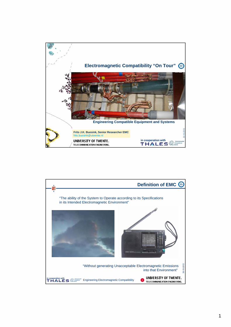
Electromagnetic Compatibility “On Tour”
Engineering Compatible Equipment and Systems
1
UNIVERSITY OF TWENTE.TELECOMMUNICATION ENGINEERING.
in cooperation withEngineering Electromagnetic Compatibility
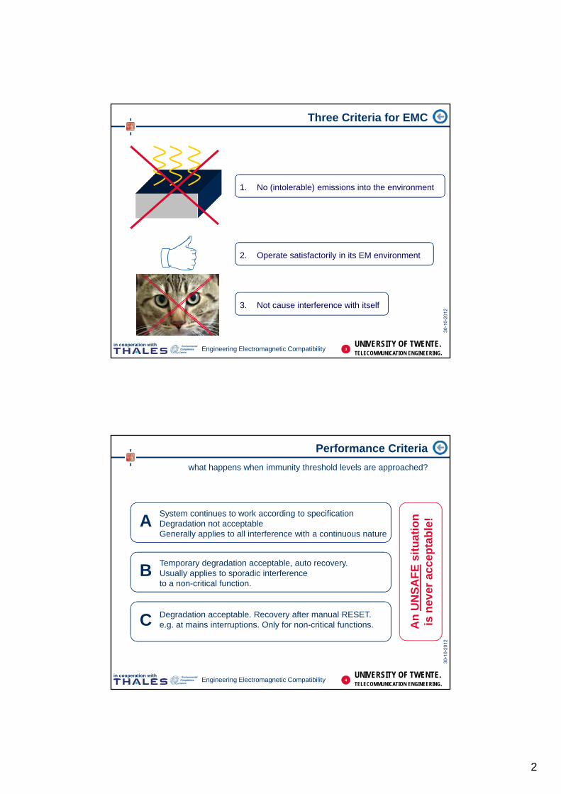
Definition of EMC
“The ability of the System to Operate according to its Specificationsin its Intended Electromagnetic Environment”
“Without generating Unacceptable Electromagnetic Emissionsinto that Environment”
2
2
UNIVERSITY OF TWENTE.TELECOMMUNICATION ENGINEERING.
in cooperation withEngineering Electromagnetic Compatibility
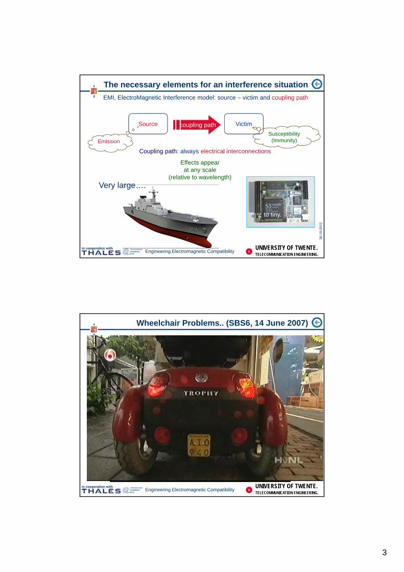
Three Criteria for EMC
1. No (intolerable) emissions into the environment
2. Operate satisfactorily in its EM environment
3. Not cause interference with itself
3
UNIVERSITY OF TWENTE.TELECOMMUNICATION ENGINEERING.
in cooperation withEngineering Electromagnetic Compatibility
Performance Criteria
what happens when immunity threshold levels are approached?
ASystem continues to work according to specificationDegradation not acceptableGenerally applies to all interference with a continuous nature
BTemporary degradation acceptable, auto recovery.Usually applies to sporadic interferenceto a non-critical function.
C Degradation acceptable. Recovery after manual RESET.e.g. at mains interruptions. Only for non-critical functions. A
n U
NS
AF
Esi
tuat
ion
is n
ever
acc
epta
ble
!
4
3
UNIVERSITY OF TWENTE.TELECOMMUNICATION ENGINEERING.
in cooperation withEngineering Electromagnetic Compatibility
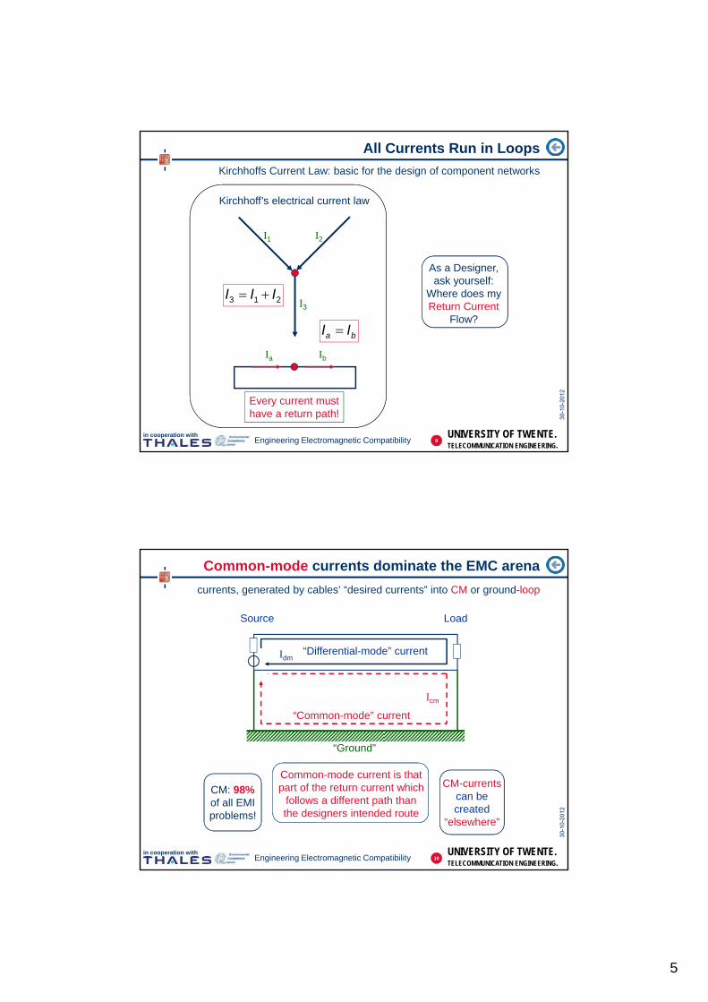
The necessary elements for an interference situation
EMI, ElectroMagnetic Interference model: source – victim and coupling path
Source Victimcoupling pathcoupling path
Coupling path: always electrical interconnections
to tiny.
EmissionSusceptibility
(Immunity)
Very large….
this can be demonstrated using: a noise generator a radio receiver and some cables
Effects appearat any scale
(relative to wavelength)
5
UNIVERSITY OF TWENTE.TELECOMMUNICATION ENGINEERING.
in cooperation withEngineering Electromagnetic Compatibility
Wheelchair Problems.. (SBS6, 14 June 2007)
6

4
UNIVERSITY OF TWENTE.TELECOMMUNICATION ENGINEERING.
in cooperation withEngineering Electromagnetic Compatibility
Two days later..
recall of all vehicles
Tubantia,16 June 2007
7
UNIVERSITY OF TWENTE.TELECOMMUNICATION ENGINEERING.
in cooperation withEngineering Electromagnetic Compatibility
Whether Pacemakers are Indeed this Susceptible?
fields up to 30 kV/m and not just 50 Hz!
8
5
UNIVERSITY OF TWENTE.TELECOMMUNICATION ENGINEERING.
in cooperation withEngineering Electromagnetic Compatibility
All Currents Run in Loops
Kirchhoffs Current Law: basic for the design of component networks
I1 I2
I3
Ia Ib
Kirchhoff’s electrical current law
213 III
ba II
Every current musthave a return path!
As a Designer,ask yourself:
Where does myReturn Current
Flow?
9
UNIVERSITY OF TWENTE.TELECOMMUNICATION ENGINEERING.
in cooperation withEngineering Electromagnetic Compatibility
Common-mode currents dominate the EMC arena
currents, generated by cables’ “desired currents” into CM or ground-loop
Source Load
“Ground”
“Differential-mode” currentIdm
Icm
“Common-mode” current
CM: 98%of all EMIproblems!
Common-mode current is thatpart of the return current which
follows a different path thanthe designers intended route
CM-currentscan becreated
“elsewhere”
10
6
UNIVERSITY OF TWENTE.TELECOMMUNICATION ENGINEERING.
in cooperation withEngineering Electromagnetic Compatibility
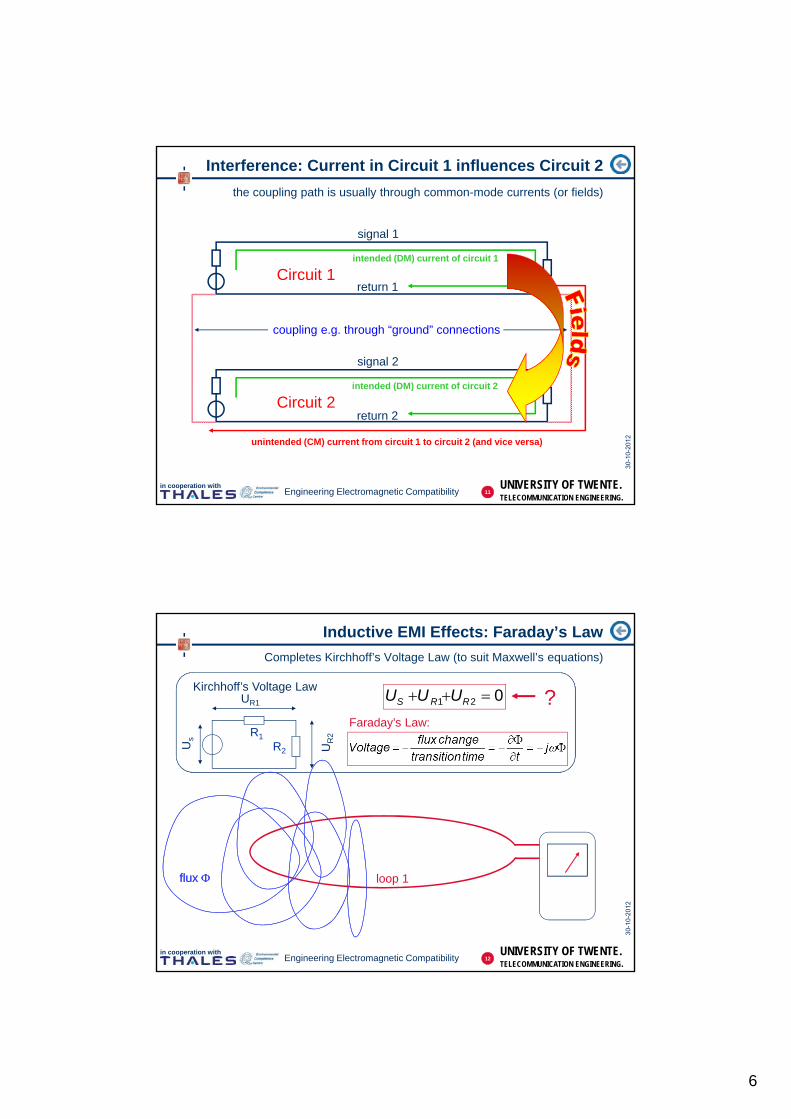
Interference: Current in Circuit 1 influences Circuit 2
the coupling path is usually through common-mode currents (or fields)
signal 1
return 1
signal 2
return 2
coupling e.g. through “ground” connections
Circuit 1
Circuit 2
intended (DM) current of circuit 1
intended (DM) current of circuit 2
unintended (CM) current from circuit 1 to circuit 2 (and vice versa)
11
UNIVERSITY OF TWENTE.TELECOMMUNICATION ENGINEERING.
in cooperation withEngineering Electromagnetic Compatibility
Kirchhoff’s Voltage Law
Us
R1
R2
UR1
UR
2
021 RRS UUU
Inductive EMI Effects: Faraday’s Law
Completes Kirchhoff’s Voltage Law (to suit Maxwell’s equations)
loop 1flux flux
Faraday’s Law:
?
12

7
UNIVERSITY OF TWENTE.TELECOMMUNICATION ENGINEERING.
in cooperation withEngineering Electromagnetic Compatibility
The phenomenon “Self-induction”
current in a conductor is only possible when magnetic field exists
50
coax cable
single wire
1. Waveform for fast edge
A B
A
B
signal integrity =no distortion onthe signal line
13
UNIVERSITY OF TWENTE.TELECOMMUNICATION ENGINEERING.
in cooperation withEngineering Electromagnetic Compatibility
The phenomenon “Self-induction”
current in a conductor is only possible when magnetic field exists
50
coax cable
1a. Waveform for fast edge@ reduced loop area
A B
A
B
Reduce loop area:less time and energy
needed to build H-field
single wire
14

8
UNIVERSITY OF TWENTE.TELECOMMUNICATION ENGINEERING.
in cooperation withEngineering Electromagnetic Compatibility
The phenomenon “Self-induction”
current in a conductor is only possible when magnetic field exists
50
coax cable
single wire
2. Waveform for slow edge
A B
A
B
15
UNIVERSITY OF TWENTE.TELECOMMUNICATION ENGINEERING.
in cooperation withEngineering Electromagnetic Compatibility
Mutual induction: coupling of circuits (loops)
Field loop 1 induces voltage in loop 2 (“Crosstalk”- or: transformer)
I1
loop 1
loop 2
MModel:
flux 1
1
212
loop
loop
IM
1
11 I
L
16

9
UNIVERSITY OF TWENTE.TELECOMMUNICATION ENGINEERING.
in cooperation withEngineering Electromagnetic Compatibility
Mutual induction in practice
two circuits with a common return (“ground”) conductor
50
50
50
source (50)
scope
“ground” litz wire
single wire (source)
single wire (passive)
Only a change in current produces crosstalk!
dt
dIVnoise ~
“Common Impedance” crosstalkPhenomenon is referred to as
“Common-Impedance” crosstalk
Note that a slower rise timeproduces less or no crosstalk at all!
17
UNIVERSITY OF TWENTE.TELECOMMUNICATION ENGINEERING.
in cooperation withEngineering Electromagnetic Compatibility
50
50
Ground Plane
Wide ground plane is preferredreturn path for current!
Wide metal reduces common impedance efficiently
the effects of Lenz Law
50
source (50)
scope
single wire (source)
single wire (passive)
“ground” litz wire
g“Common-Impedance” of wireis high compared to wide plate
Icm “squeezes”under cable
(proximityeffect)
18
10
UNIVERSITY OF TWENTE.TELECOMMUNICATION ENGINEERING.
in cooperation withEngineering Electromagnetic Compatibility
Wide metal also features: the Skin Effect
Lenz’Law and the basis for shielding effects
CurrentSource
0 d
Edd
y cu
rren
ts
curr
ent d
ensi
ty
0 d
J0
e
J0d
d eJJ
0
Induced Eddy currents opposedirection of external current
(Lenz’ Law)
f
1 f = frequency [Hz] = conductivity [S/m] = permeability [H/m]
19
UNIVERSITY OF TWENTE.TELECOMMUNICATION ENGINEERING.
in cooperation withEngineering Electromagnetic Compatibility
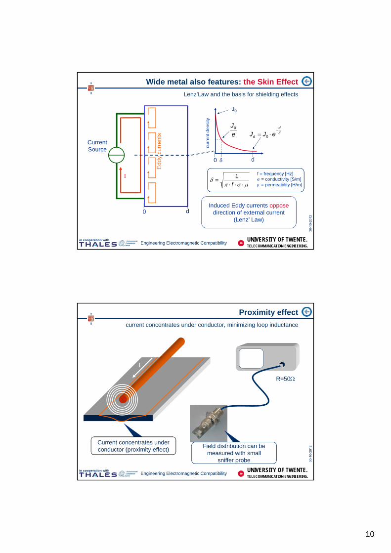
Proximity effect
current concentrates under conductor, minimizing loop inductance
Current concentrates underconductor (proximity effect)
R=50
Field distribution can bemeasured with small
sniffer probe
20

11
UNIVERSITY OF TWENTE.TELECOMMUNICATION ENGINEERING.
in cooperation withEngineering Electromagnetic Compatibility
Cables are used to keep Signal and Return together
field of the return conductor is identical but opposite (if geometry is identical)
H = Magnetic Field [A/m] - H
Ir
rH
2
Ampere’s Law:
21
UNIVERSITY OF TWENTE.TELECOMMUNICATION ENGINEERING.
in cooperation withEngineering Electromagnetic Compatibility
Current carrying conductor always exhibits H-field
minimize fields by locating the return conductor concentric
22
12
UNIVERSITY OF TWENTE.TELECOMMUNICATION ENGINEERING.
in cooperation withEngineering Electromagnetic Compatibility
external noise source
Inoise
Unoise
1. Coupling into external noise
cable length D
Properties of cables: Transfer Impedance ZT
cable may produce or pick up common mode currents
Idesired
return current flows where?
?
2. Generation of noise in other conductors(e.g. “ground”)
DI
UZ
noise
noiseT
[Ohm per meter]
23
UNIVERSITY OF TWENTE.TELECOMMUNICATION ENGINEERING.
in cooperation withEngineering Electromagnetic Compatibility
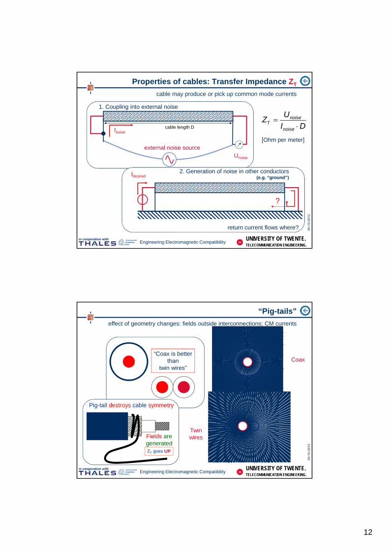
“Pig-tails”
effect of geometry changes: fields outside interconnections; CM currents
whencompared…
“Coax is betterthan
twin wires”Coax
Twinwires
Pig-tail destroys cable symmetry
Fields aregeneratedZT goes UP
24
13
UNIVERSITY OF TWENTE.TELECOMMUNICATION ENGINEERING.
in cooperation withEngineering Electromagnetic Compatibility
Icm
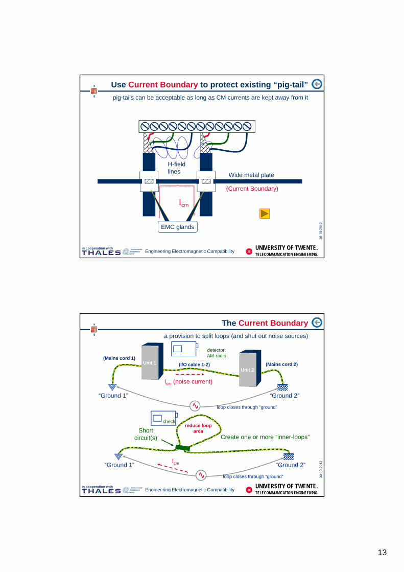
Use Current Boundary to protect existing “pig-tail”
pig-tails can be acceptable as long as CM currents are kept away from it
H-fieldlines
Wide metal plate
(Current Boundary)
EMC glands
25
UNIVERSITY OF TWENTE.TELECOMMUNICATION ENGINEERING.
in cooperation withEngineering Electromagnetic Compatibility
The Current Boundary
a provision to split loops (and shut out noise sources)
“Ground 1” “Ground 2”
Icm (noise current)
loop closes through “ground”
“Ground 2”“Ground 1”Icm
loop closes through “ground”
Create one or more “inner-loops”Short
circuit(s)
reduce looparea
check
Unit 1
Unit 2
(Mains cord 1)(Mains cord 2)(I/O cable 1-2)
Situation in practicedetector:AM-radio
26
14
UNIVERSITY OF TWENTE.TELECOMMUNICATION ENGINEERING.
in cooperation withEngineering Electromagnetic Compatibility
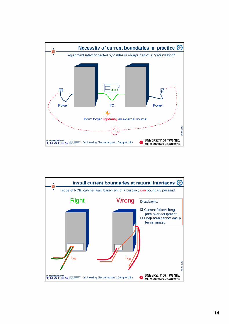
Necessity of current boundaries in practice
equipment interconnected by cables is always part of a “ground loop”
Power PowerI/O
check
Don’t forget lightning as external source!
27
UNIVERSITY OF TWENTE.TELECOMMUNICATION ENGINEERING.
in cooperation withEngineering Electromagnetic Compatibility
Install current boundaries at natural interfaces
edge of PCB, cabinet wall, basement of a building; one boundary per unit!
Right Wrong
Icm Icm
Drawbacks:
Current follows longpath over equipment
Loop area cannot easilybe minimized
28

15
UNIVERSITY OF TWENTE.TELECOMMUNICATION ENGINEERING.
in cooperation withEngineering Electromagnetic Compatibility
Examples of current boundaries on equipment
wide conductors and low-resistance transitions (be careful with paint) !
protect all units with a current boundary!(and check any conductor that passes it)
Short
Wid
e
check DC resistance witha milli- meter: < 1 m!
NoPaint!
29
UNIVERSITY OF TWENTE.TELECOMMUNICATION ENGINEERING.
in cooperation withEngineering Electromagnetic Compatibility
What goes wrong on current boundaries…
mix of plastic and metal EMC glands signals errors
Metal gland onplastic cable sheath
No cable shield…no connection
either ??
Paint….?
30
16
UNIVERSITY OF TWENTE.TELECOMMUNICATION ENGINEERING.
in cooperation withEngineering Electromagnetic Compatibility
Separating cables with current boundaries
classify cables into categories
Model
ICM
Category
red = “source” =“Emission”
1. Noisy (E)
green =“sensitive” =“Immunity”
2. Sensitive (I)
blue =“indifferent” =
“Neutral”
3. Indifferent (N)
E
I N
31
UNIVERSITY OF TWENTE.TELECOMMUNICATION ENGINEERING.
in cooperation withEngineering Electromagnetic Compatibility
1. herken kringN
Steps:
Separating cables with current boundaries
use Neutral conductor to reduce loop area; then insert current boundary
1. recognize loop
E
I2. reduce looparea
N
3. add boundary
32
17
UNIVERSITY OF TWENTE.TELECOMMUNICATION ENGINEERING.
in cooperation withEngineering Electromagnetic Compatibility
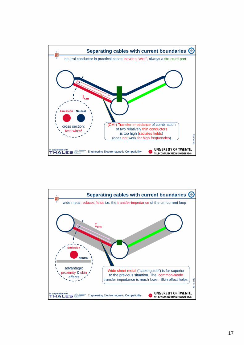
Separating cables with current boundaries
neutral conductor in practical cases: never a “wire”, always a structure part
cm
cross section:twin wires!
Emission Neutral
(CM-) Transfer impedance of combinationof two relatively thin conductors
is too high (radiates fields)(does not work for high frequencies)
33
UNIVERSITY OF TWENTE.TELECOMMUNICATION ENGINEERING.
in cooperation withEngineering Electromagnetic Compatibility
Separating cables with current boundaries
wide metal reduces fields i.e. the transfer-impedance of the cm-current loop
cm
advantage:proximity & skin
effects
Emission
Neutral
Wide sheet metal (“cable guide”) is far superiorto the previous situation. The common-mode
transfer impedance is much lower. Skin effect helps.
34

18
UNIVERSITY OF TWENTE.TELECOMMUNICATION ENGINEERING.
in cooperation withEngineering Electromagnetic Compatibility
“Plane” could be metal mesh
Separating cables with current boundaries
use (Ground-) Plane to reduce loop area; then insert current boundaries
NSteps:1. recognize loop
E
I
3. connect current boundaries to plane
2. cover loop with metal (ground-)plane
35
UNIVERSITY OF TWENTE.TELECOMMUNICATION ENGINEERING.
in cooperation withEngineering Electromagnetic Compatibility
Special form of current boundary: a cable guide
Neutral conductor, usually structural part of existing installation
50
50
Cable 1 (source)
Cable 2 (passive)
Tracking-generator
U
f
spectrumanalyser
I CM
(=
no
ise
)
ICM (=noise)
Icm “squeezes”under cable
(proximity effect)36
19
UNIVERSITY OF TWENTE.TELECOMMUNICATION ENGINEERING.
in cooperation with
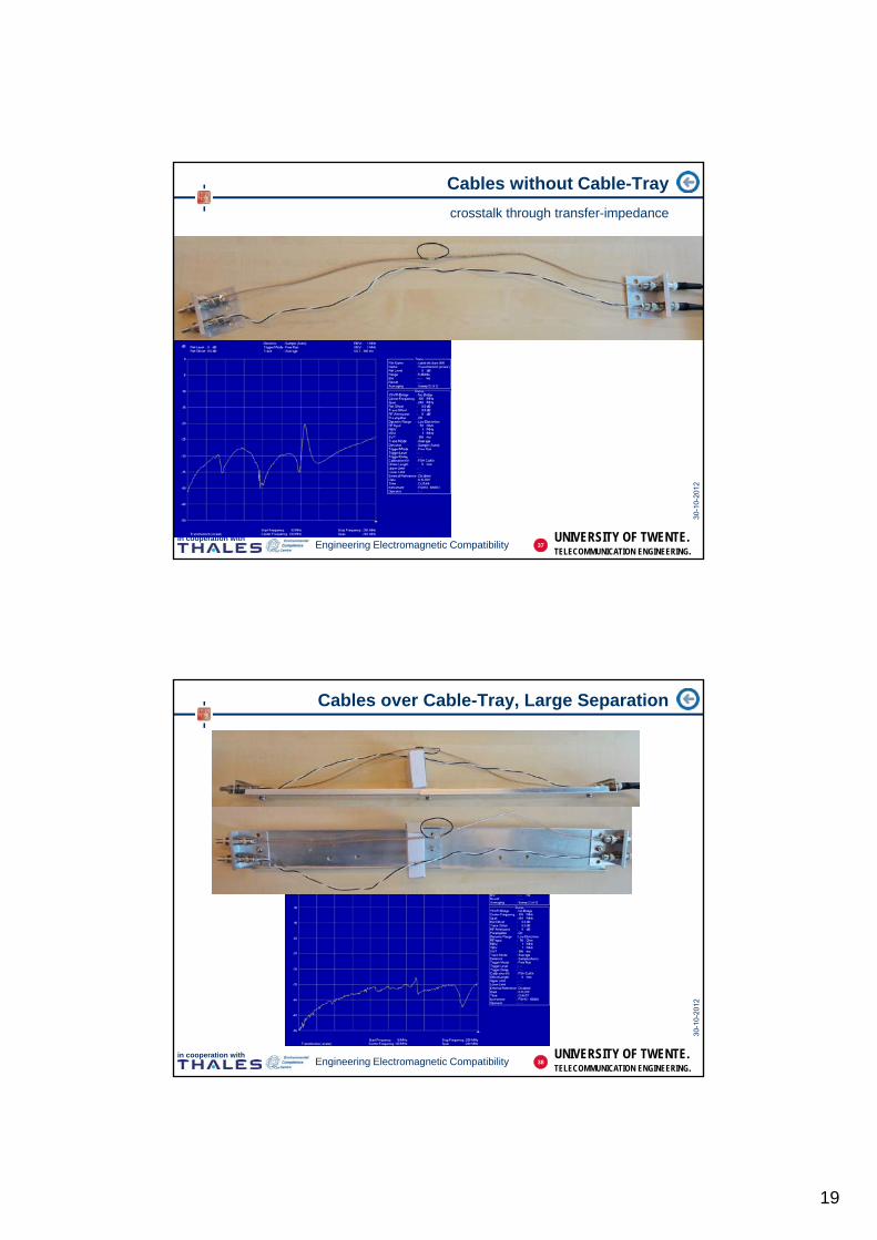
Cables without Cable-Tray
crosstalk through transfer-impedance
37Engineering Electromagnetic Compatibility
UNIVERSITY OF TWENTE.TELECOMMUNICATION ENGINEERING.
in cooperation with
Cables over Cable-Tray, Large Separation
38Engineering Electromagnetic Compatibility
20
UNIVERSITY OF TWENTE.TELECOMMUNICATION ENGINEERING.
in cooperation with
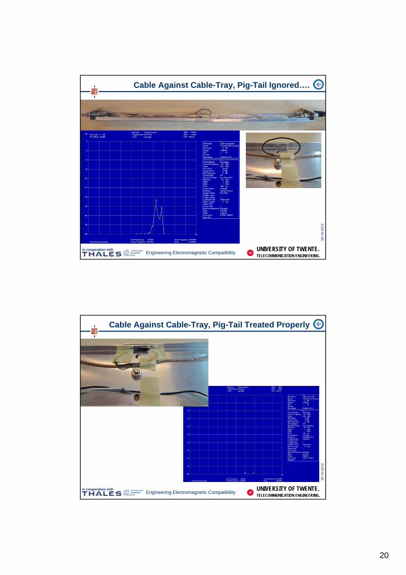
Cable Against Cable-Tray, Pig-Tail Ignored….
39Engineering Electromagnetic Compatibility
UNIVERSITY OF TWENTE.TELECOMMUNICATION ENGINEERING.
in cooperation with
Cable Against Cable-Tray, Pig-Tail Treated Properly
40Engineering Electromagnetic Compatibility
21
UNIVERSITY OF TWENTE.TELECOMMUNICATION ENGINEERING.
in cooperation withEngineering Electromagnetic Compatibility
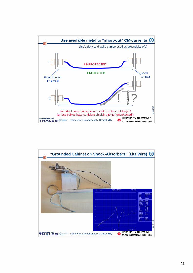
Use available metal to “short-out” CM-currents
ship’s deck and walls can be used as groundplane(s)
Important: keep cables near metal over their full length!(unless cables have sufficient shielding to go “unprotected”)
UNPROTECTED
PROTECTEDGood contact
(< 1 m)
Goodcontact
?!
41
UNIVERSITY OF TWENTE.TELECOMMUNICATION ENGINEERING.
in cooperation with
“Grounded Cabinet on Shock-Absorbers” (Litz Wire)
42Engineering Electromagnetic Compatibility

22
UNIVERSITY OF TWENTE.TELECOMMUNICATION ENGINEERING.
in cooperation with
Cabinet on Wide Grounding Bracket, Cables Float
43Engineering Electromagnetic Compatibility
UNIVERSITY OF TWENTE.TELECOMMUNICATION ENGINEERING.
in cooperation with
Cabinet on Wide Grounding Bracket, Cables Improved
44Engineering Electromagnetic Compatibility
23
UNIVERSITY OF TWENTE.TELECOMMUNICATION ENGINEERING.
in cooperation withEngineering Electromagnetic Compatibility
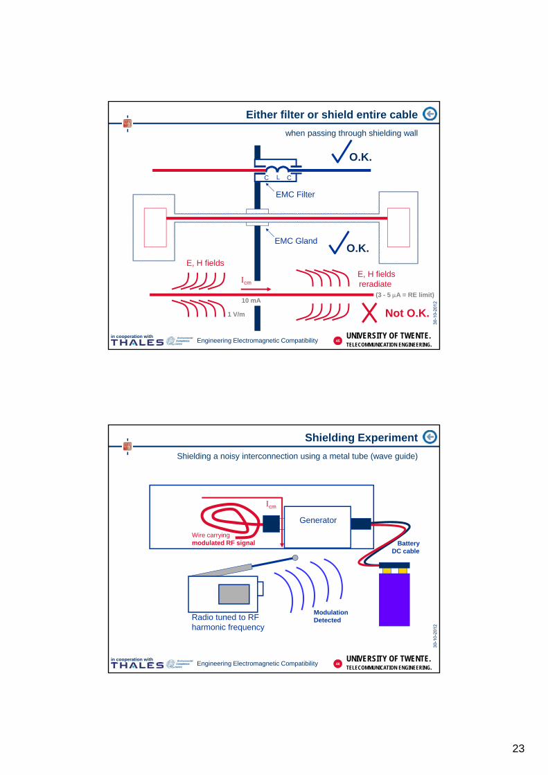
Either filter or shield entire cable
when passing through shielding wall
EMC Gland
C L C
EMC Filter
O.K.
O.K.
Not O.K.
cm
E, H fields E, H fieldsreradiate
1 V/m
10 mA(3 - 5 A = RE limit)
45
UNIVERSITY OF TWENTE.TELECOMMUNICATION ENGINEERING.
in cooperation withEngineering Electromagnetic Compatibility
Shielding Experiment
Shielding a noisy interconnection using a metal tube (wave guide)
Wire carryingmodulated RF signal Battery
DC cable
Generator
Radio tuned to RFharmonic frequency
ModulationDetected
cm
46

24
UNIVERSITY OF TWENTE.TELECOMMUNICATION ENGINEERING.
in cooperation withEngineering Electromagnetic Compatibility
Shielding Experiment
Entering a conductor into tube couples out the noise again
Wire carryingmodulated RF signal Battery
DC cable
Generator
Radio tuned to RFharmonic frequency
ModulationDetected
47
UNIVERSITY OF TWENTE.TELECOMMUNICATION ENGINEERING.
in cooperation withEngineering Electromagnetic Compatibility
Shielding Experiment
Insulating generator case: battery cable now reradiates noise (antenna)
Wire carryingmodulated RF signal Battery
DC cable
Generator
Radio tuned to RFharmonic frequency
ModulationDetected
cm
48
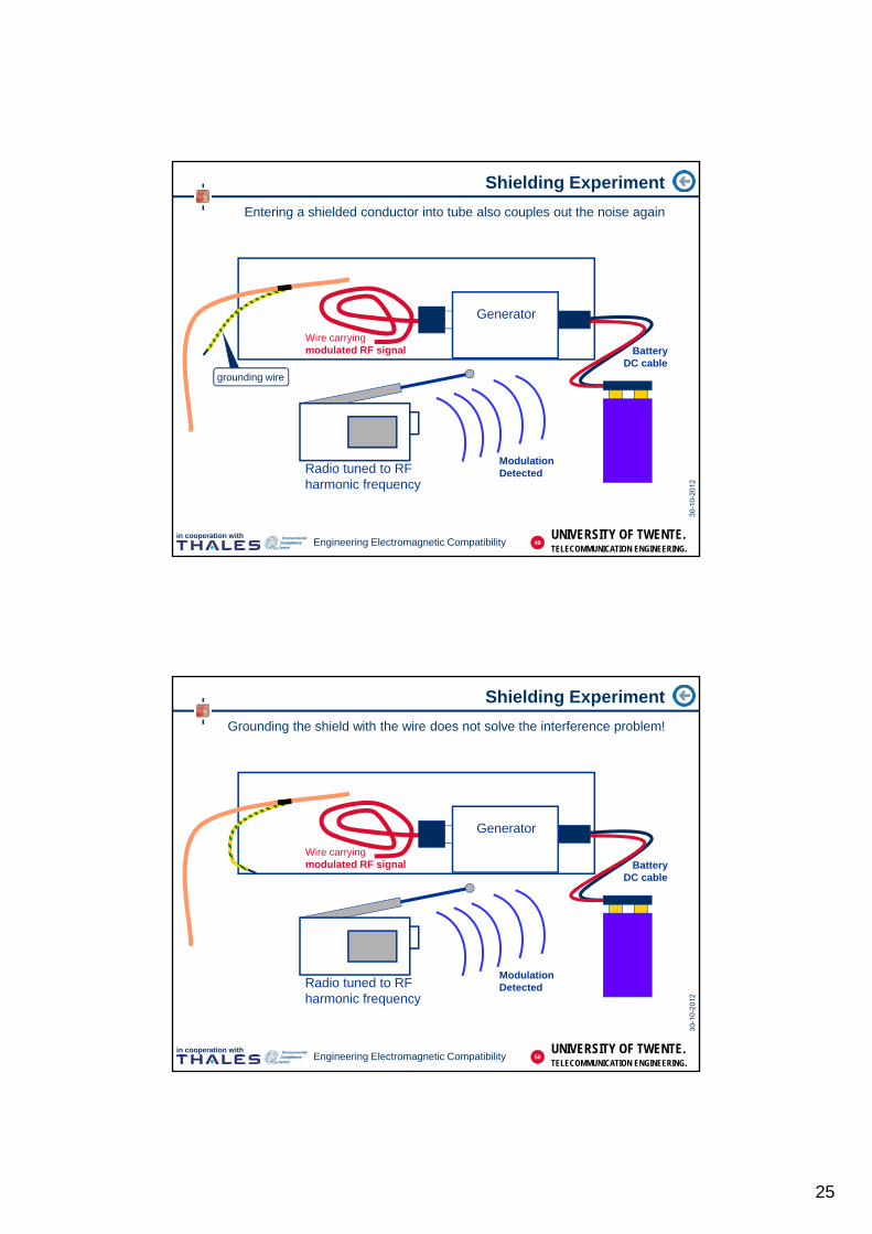
25
UNIVERSITY OF TWENTE.TELECOMMUNICATION ENGINEERING.
in cooperation withEngineering Electromagnetic Compatibility
Shielding Experiment
Entering a shielded conductor into tube also couples out the noise again
Wire carryingmodulated RF signal Battery
DC cable
Generator
Radio tuned to RFharmonic frequency
ModulationDetected
grounding wire
49
UNIVERSITY OF TWENTE.TELECOMMUNICATION ENGINEERING.
in cooperation withEngineering Electromagnetic Compatibility
Shielding Experiment
Grounding the shield with the wire does not solve the interference problem!
Wire carryingmodulated RF signal Battery
DC cable
Generator
Radio tuned to RFharmonic frequency
ModulationDetected
50
26
UNIVERSITY OF TWENTE.TELECOMMUNICATION ENGINEERING.
in cooperation withEngineering Electromagnetic Compatibility
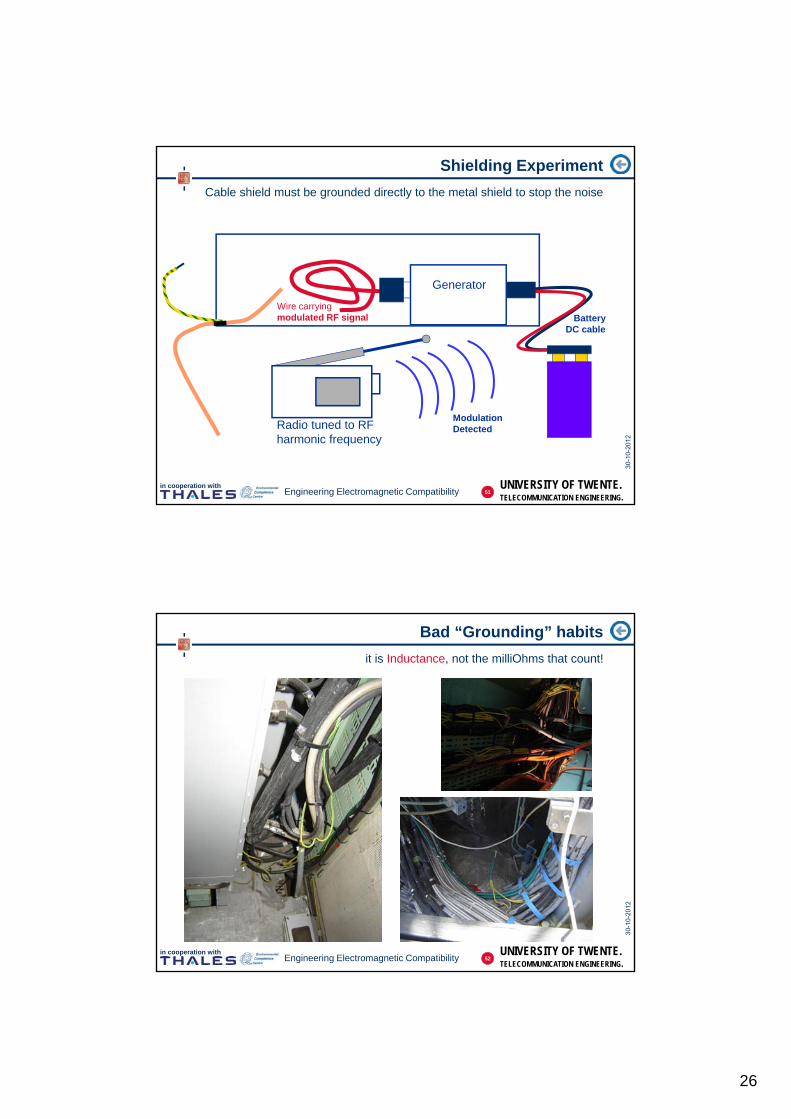
Shielding Experiment
Cable shield must be grounded directly to the metal shield to stop the noise
Wire carryingmodulated RF signal Battery
DC cable
Generator
Radio tuned to RFharmonic frequency
ModulationDetected
51
UNIVERSITY OF TWENTE.TELECOMMUNICATION ENGINEERING.
in cooperation withEngineering Electromagnetic Compatibility
Bad “Grounding” habits
it is Inductance, not the milliOhms that count!
52
27
UNIVERSITY OF TWENTE.TELECOMMUNICATION ENGINEERING.
in cooperation withEngineering Electromagnetic Compatibility
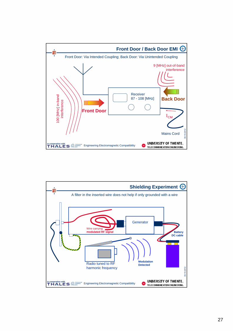
Front Door / Back Door EMI
Front Door: Via Intended Coupling; Back Door: Via Unintended Coupling
Receiver87 - 108 [MHz]
Mains Cord
100
[MH
z] in
-ban
din
terf
eren
ce
Front DoorCM
9 [MHz] out-of-bandinterference
Back Door
53
UNIVERSITY OF TWENTE.TELECOMMUNICATION ENGINEERING.
in cooperation withEngineering Electromagnetic Compatibility
Shielding Experiment
A filter in the inserted wire does not help if only grounded with a wire
Wire carryingmodulated RF signal Battery
DC cable
Generator
Radio tuned to RFharmonic frequency
ModulationDetected
54
28
UNIVERSITY OF TWENTE.TELECOMMUNICATION ENGINEERING.
in cooperation withEngineering Electromagnetic Compatibility
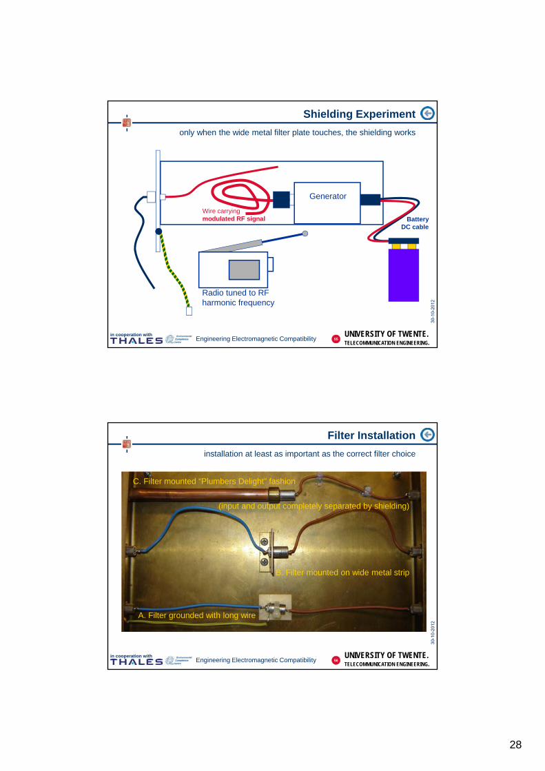
Shielding Experiment
only when the wide metal filter plate touches, the shielding works
Wire carryingmodulated RF signal Battery
DC cable
Generator
Radio tuned to RFharmonic frequency
55
UNIVERSITY OF TWENTE.TELECOMMUNICATION ENGINEERING.
in cooperation withEngineering Electromagnetic Compatibility
Filter Installation
installation at least as important as the correct filter choice
A. Filter grounded with long wire
B. Filter mounted on wide metal strip
C. Filter mounted “Plumbers Delight” fashion
(input and output completely separated by shielding)
56

29
UNIVERSITY OF TWENTE.TELECOMMUNICATION ENGINEERING.
in cooperation withEngineering Electromagnetic Compatibility
Filter Grounded with Long Wire
some effect in the low frequency range; hardly any in higher frequencies
57
UNIVERSITY OF TWENTE.TELECOMMUNICATION ENGINEERING.
in cooperation withEngineering Electromagnetic Compatibility
Filter Mounted on Wide Metal Strip
better than the long wire; sensitive to cable routing (crosstalk)
Wires pressed against ground plane
Wires far from ground plane
58
30
UNIVERSITY OF TWENTE.TELECOMMUNICATION ENGINEERING.
in cooperation withEngineering Electromagnetic Compatibility
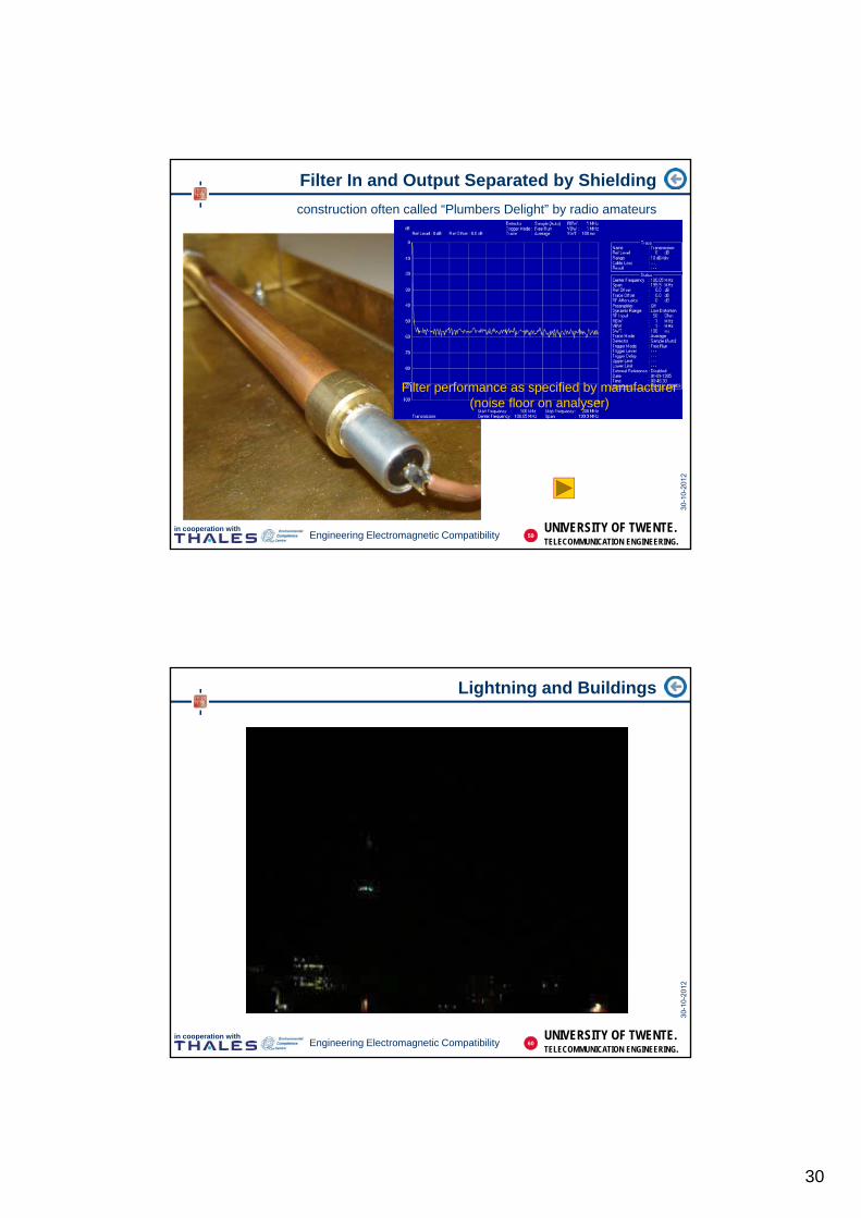
Filter In and Output Separated by Shielding
construction often called “Plumbers Delight” by radio amateurs
Filter performance as specified by manufacturer(noise floor on analyser)
59
UNIVERSITY OF TWENTE.TELECOMMUNICATION ENGINEERING.
in cooperation withEngineering Electromagnetic Compatibility
Lightning and Buildings
60

31
UNIVERSITY OF TWENTE.TELECOMMUNICATION ENGINEERING.
in cooperation withEngineering Electromagnetic Compatibility
Insulation in Lightning Protection
keep lightning current on the outside of the buildingE
xter
nal “
Shi
eld”
Inte
rnal
wiri
ng
surgeprotect
cabinet
1
2
3
4
5
power
data
RV
Ext
erna
l con
duct
ing
stru
ctur
e
CurrentBoundary
61
UNIVERSITY OF TWENTE.TELECOMMUNICATION ENGINEERING.
in cooperation withEngineering Electromagnetic Compatibility
Lightning and Airplanes
62
32
UNIVERSITY OF TWENTE.TELECOMMUNICATION ENGINEERING.
in cooperation withEngineering Electromagnetic Compatibility
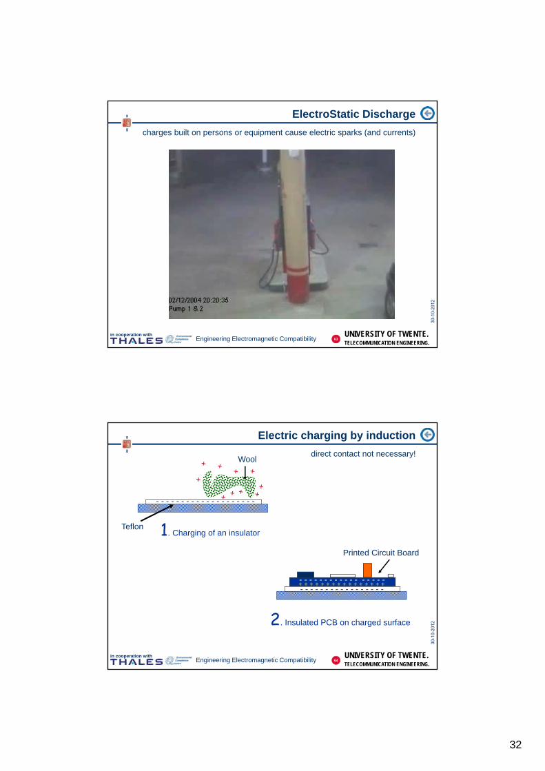
ElectroStatic Discharge
charges built on persons or equipment cause electric sparks (and currents)
63
UNIVERSITY OF TWENTE.TELECOMMUNICATION ENGINEERING.
in cooperation withEngineering Electromagnetic Compatibility
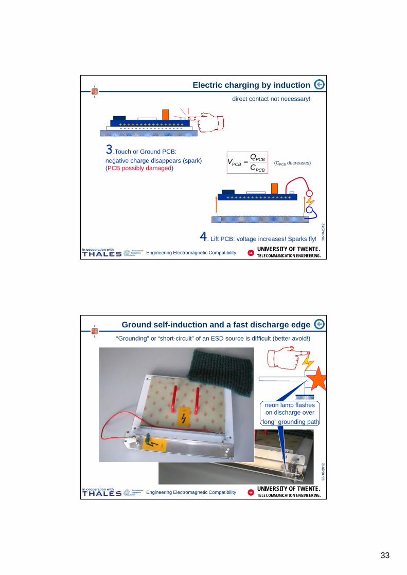
Electric charging by induction
direct contact not necessary!
Teflon
Wool
Printed Circuit Board
- - - - - - - - - - - - - - - - -+ + + + + + + + + + + + + + + +
1. Charging of an insulator
2. Insulated PCB on charged surface
- - - - - - - - - - - - - - - - - - - -
- - - - - - - - - - - - - - - - -
64
33
UNIVERSITY OF TWENTE.TELECOMMUNICATION ENGINEERING.
in cooperation withEngineering Electromagnetic Compatibility
Electric charging by induction
direct contact not necessary!
+ + + + + + + + + + + + + + + +
3.Touch or Ground PCB:
negative charge disappears (spark)(PCB possibly damaged)
4. Lift PCB: voltage increases! Sparks fly!
- - - - - - - - - - - - - - - - -
- - - - - - - - - - - - - - - - -
- - - - - - - - - - - - - - - - -
+ + + + + + + + + + + + + + + +
PCB
PCBPCB C
QV (CPCB decreases)
65
UNIVERSITY OF TWENTE.TELECOMMUNICATION ENGINEERING.
in cooperation withEngineering Electromagnetic Compatibility
Ground self-induction and a fast discharge edge
“Grounding” or “short-circuit” of an ESD source is difficult (better avoid!)
“long” grounding path
neon lamp flasheson discharge over
“long” grounding path
66

34
UNIVERSITY OF TWENTE.TELECOMMUNICATION ENGINEERING.
in cooperation withEngineering Electromagnetic Compatibility
Inductive load switching
Relays, Valves, and PWM motor control systems
V0
SW
L
C(parasitic)
R(parasitic)
Basic model
0
2
2
1 LEnergy
par
2
2
1VCEnergy
22
2
1
2
1VCL
L= 0.1 HC= 100 pF = 1 A
V = 32 kV (!)
Analysis:
Source: Jasper J. Goedbloed, “EMC”Prentice Hall/Kluwer 1992
67
UNIVERSITY OF TWENTE.TELECOMMUNICATION ENGINEERING.
in cooperation withEngineering Electromagnetic Compatibility
High Voltage in Motor arcs and creates Spikes
reason for Electrical Fast Transients (EFT) tests on equipment
ampl
itude
time (s scale)
breakdown (ns scale)
from EN 61000-4-4
5/50 ns pulses
68
35
UNIVERSITY OF TWENTE.TELECOMMUNICATION ENGINEERING.
in cooperation withEngineering Electromagnetic Compatibility
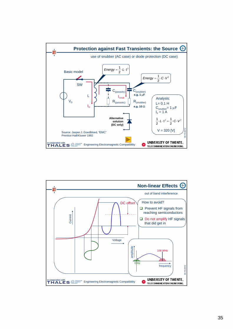
Protection against Fast Transients: the Source
use of snubber (AC case) or diode protection (DC case)
C(parasitic)
R(parasitic)V0
SW
L
Basic model
0
2
2
1 LEnergy
snub
2
2
1VCEnergy
22
2
1
2
1VCL
L= 0.1 HCsnubber= 1 F = 1 A
V = 320 [V]
Analysis:
Source: Jasper J. Goedbloed, “EMC”Prentice Hall/Kluwer 1992
C(snubber)
R(snubber)
e.g. 1 F
e.g. 10
Alternativesolution
(DC only)
69
UNIVERSITY OF TWENTE.TELECOMMUNICATION ENGINEERING.
in cooperation withEngineering Electromagnetic Compatibility
Non-linear Effects
out of band interference
Voltage
Cur
rent
DC offset
frequency
ampl
itude
100 MHz
0 Hz
How to avoid?
Prevent HF signals fromreaching semiconductors
Do not amplify HF signalsthat did get in
70
36
UNIVERSITY OF TWENTE.TELECOMMUNICATION ENGINEERING.
in cooperation withEngineering Electromagnetic Compatibility
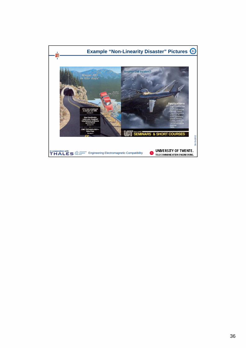
Example “Non-Linearity Disaster” Pictures
71