electromagnetic field simulation for icrf antenna and ... · electromagnetic field simulation for...
TRANSCRIPT

Plasma and Fusion Research: Regular Articles Volume 5, S2104 (2010)
Electromagnetic Field Simulation for ICRF Antenna andComparison with Experimental Results in LHD
Takashi MUTOH, Hiroshi KASAHARA, Tetsuo SEKI, Kenji SAITO,Ryuhei KUMAZAWA, Fujio SHIMPO and Goro NOMURA
National Institute for Fusion Science, 322-6 Oroshi-cho, Toki 509-5292, Japan
(Received 8 January 2010 / Accepted 26 February 2010)
Ion cyclotron range of frequencies (ICRF) heating antennas in LHD are numerically simulated and analyzedby HFSSTM finite-element electromagnetic wave field calculation code. The model includes an accurate vacuumchamber wall of LHD and ICRF antenna structure and a simple model of plasma in a helical configuration.Antenna coupling with plasma is simulated by an artificial freshwater volume with enhanced high permittivityof ε = 500-2000. RF current distribution and electromagnetic field distribution on and near the ICRF antennaare analyzed and well elucidated through a comparison with the experimental results. The frequency dependenceof experimental loading resistance can be simulated by the calculation, and the RF dissipation on the antennastructure is studied and compared with experimental results. The local high heat load around gaps betweenthe carbon side protectors is well explained, and the effect of gap distance is studied. Comparison with theexperimental results reveals that the ICRF heating in the LHD, including the antenna and helical plasma, is wellsimulated by commercial HFSSTM code analysis. It will also be useful for future improvements in ICRF antennadesign in helical devices.c© 2010 The Japan Society of Plasma Science and Nuclear Fusion Research
Keywords: ICRF antenna, RF heating, LHD, helical device, HFSS code, electromagnetic wave
DOI: 10.1585/pfr.5.S2104
1. IntroductionIon cyclotron range of frequencies (ICRF) heating
method is considered as one of the most promising tech-nologies for heating future fusion devices. The optimiza-tion of antennas for physics and technological applicationsis very important to build up an efficient, high-power heat-ing system. Normally the R&D process requires many ex-periences of plasma heating experiments, and a long timeis needed to optimize antenna design. In helical systems,high power ICRF heating experiment is now testing onlyone device in LHD [1–4]. Therefore, numerical simula-tion is very helpful to optimize antenna design, becausethe experimental trial of any change to the antenna struc-ture is very limited. To improve the plasma coupling andstand-off voltage, numerical code calculation is beneficialand is needed to save time in the R&D process. In thispaper, numerically calculated results of antenna coupling,heat load due to dissipated RF power, and electromagneticfield distribution are studied and compared with experi-mental observations. The electromagnetic field calcula-tion code, called HFSS (High-Frequency Structure Sim-ulator, HFSSTM [5]), is used for this purpose. The code isa commercial finite element method calculation code andis widely used to analyze microwave and high-frequencycircuits.
The ICRF antennas in an LHD vacuum chamber
author’s e-mail: [email protected]
shown in Fig. 1 are located on the outer side of the toroid[6]. The chamber has a complicated helical structure, as
Fig. 1 Two sets of ICRF antennas are set on the outer side totoroid in the LHD vacuum chamber. They are positionedin front of the superconducting helical windings.
c© 2010 The Japan Society of PlasmaScience and Nuclear Fusion Research
S2104-1
Plasma and Fusion Research: Regular Articles Volume 5, S2104 (2010)
the figure shows. The positions of the cyclotron reso-nances and fast-wave cutoff surfaces of the LHD are quiteunique and different [1, 2] from those of tokamaks. Thepoloidal cross section of plasma has an oval shape and ro-tates along the helical structure to the toroidal direction.The antenna front surface is three-dimensionally twistedto fit the scrape-off layer of the helical LHD plasma. Onepair of loop antennas is composed of two separate anten-nas each of which has a single current strap and is indepen-dently fed from the top and bottom vacuum ports, respec-tively. The Faraday shield pipes are inclined to cancel theelectric field along the confinement magnetic field lines, asshown in Fig. 1.
2. Simulation Model and AntennaCoupling CharacteristicsElectromagnetic field calculation using 3-D HFSS
simulation code was carried out on a finely detailed modelof the LHD ICRF antennas and surrounding hardware. Therealistic configuration included precise replications of thetwisted antenna conductors, inclined Faraday screen, andcarbon side protectors. The LHD vacuum chamber wallof stainless steel was also realistically modeled and in-cluded. Figure 2 shows the calculation model of the ICRFantenna and LHD vacuum chamber. The chamber of a 1/10torus section is included, and both ends of the toroidal cutare defined as the free radiation boundaries for the elec-tromagnetic wave. The LHD plasma model is composedof a freshwater material with artificial permittivity insteadof real plasma. Fresh water is a better material as dielec-tric absorbing material for simulation model than salt waterwhich used in many calculations. Using the salt water, theelectromagnetic field emitted from antenna is shielded byhigh electric conductivity and it cannot propagate inside ofplasma area. As described later, fresh water with high per-mittivity behaves as a good plasma model to simulate thenatural antenna-coupling characteristics.
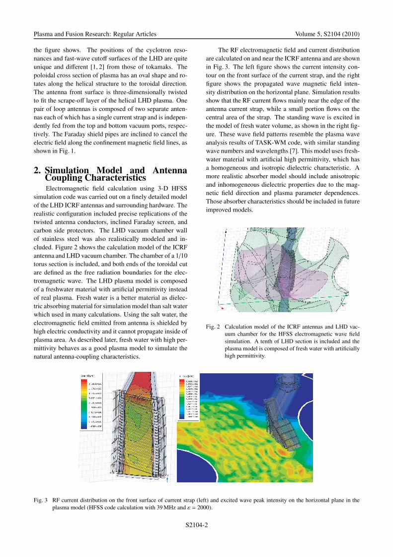
The RF electromagnetic field and current distributionare calculated on and near the ICRF antenna and are shownin Fig. 3. The left figure shows the current intensity con-tour on the front surface of the current strap, and the rightfigure shows the propagated wave magnetic field inten-sity distribution on the horizontal plane. Simulation resultsshow that the RF current flows mainly near the edge of theantenna current strap, while a small portion flows on thecentral area of the strap. The standing wave is excited inthe model of fresh water volume, as shown in the right fig-ure. These wave field patterns resemble the plasma waveanalysis results of TASK-WM code, with similar standingwave numbers and wavelengths [7]. This model uses fresh-water material with artificial high permittivity, which hasa homogeneous and isotropic dielectric characteristic. Amore realistic absorber model should include anisotropicand inhomogeneous dielectric properties due to the mag-netic field direction and plasma parameter dependences.Those absorber characteristics should be included in futureimproved models.
Fig. 2 Calculation model of the ICRF antennas and LHD vac-uum chamber for the HFSS electromagnetic wave fieldsimulation. A tenth of LHD section is included and theplasma model is composed of fresh water with artificiallyhigh permittivity.
Fig. 3 RF current distribution on the front surface of current strap (left) and excited wave peak intensity on the horizontal plane in theplasma model (HFSS code calculation with 39 MHz and ε = 2000).
S2104-2
Plasma and Fusion Research: Regular Articles Volume 5, S2104 (2010)
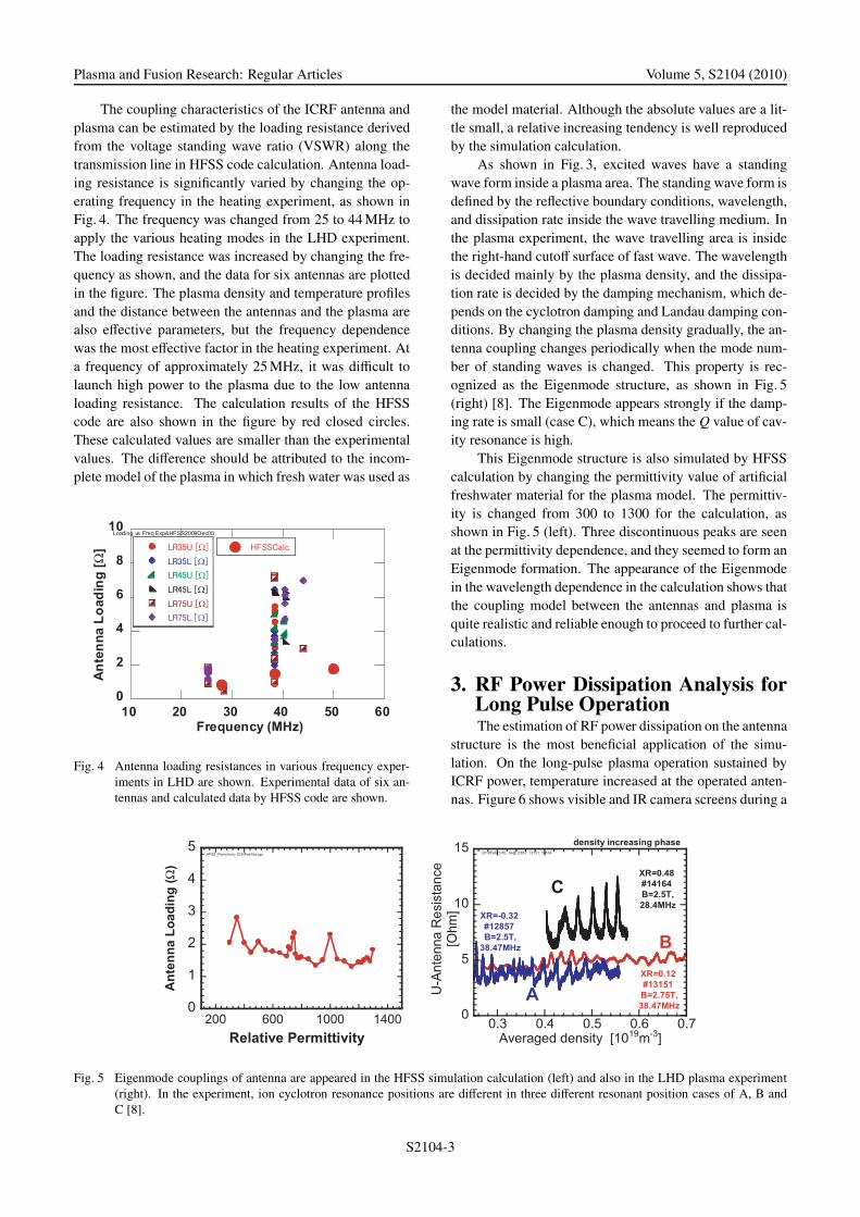
The coupling characteristics of the ICRF antenna andplasma can be estimated by the loading resistance derivedfrom the voltage standing wave ratio (VSWR) along thetransmission line in HFSS code calculation. Antenna load-ing resistance is significantly varied by changing the op-erating frequency in the heating experiment, as shown inFig. 4. The frequency was changed from 25 to 44 MHz toapply the various heating modes in the LHD experiment.The loading resistance was increased by changing the fre-quency as shown, and the data for six antennas are plottedin the figure. The plasma density and temperature profilesand the distance between the antennas and the plasma arealso effective parameters, but the frequency dependencewas the most effective factor in the heating experiment. Ata frequency of approximately 25 MHz, it was difficult tolaunch high power to the plasma due to the low antennaloading resistance. The calculation results of the HFSScode are also shown in the figure by red closed circles.These calculated values are smaller than the experimentalvalues. The difference should be attributed to the incom-plete model of the plasma in which fresh water was used as
Fig. 4 Antenna loading resistances in various frequency exper-iments in LHD are shown. Experimental data of six an-tennas and calculated data by HFSS code are shown.
Fig. 5 Eigenmode couplings of antenna are appeared in the HFSS simulation calculation (left) and also in the LHD plasma experiment(right). In the experiment, ion cyclotron resonance positions are different in three different resonant position cases of A, B andC [8].
the model material. Although the absolute values are a lit-tle small, a relative increasing tendency is well reproducedby the simulation calculation.
As shown in Fig. 3, excited waves have a standingwave form inside a plasma area. The standing wave form isdefined by the reflective boundary conditions, wavelength,and dissipation rate inside the wave travelling medium. Inthe plasma experiment, the wave travelling area is insidethe right-hand cutoff surface of fast wave. The wavelengthis decided mainly by the plasma density, and the dissipa-tion rate is decided by the damping mechanism, which de-pends on the cyclotron damping and Landau damping con-ditions. By changing the plasma density gradually, the an-tenna coupling changes periodically when the mode num-ber of standing waves is changed. This property is rec-ognized as the Eigenmode structure, as shown in Fig. 5(right) [8]. The Eigenmode appears strongly if the damp-ing rate is small (case C), which means the Q value of cav-ity resonance is high.
This Eigenmode structure is also simulated by HFSScalculation by changing the permittivity value of artificialfreshwater material for the plasma model. The permittiv-ity is changed from 300 to 1300 for the calculation, asshown in Fig. 5 (left). Three discontinuous peaks are seenat the permittivity dependence, and they seemed to form anEigenmode formation. The appearance of the Eigenmodein the wavelength dependence in the calculation shows thatthe coupling model between the antennas and plasma isquite realistic and reliable enough to proceed to further cal-culations.
3. RF Power Dissipation Analysis forLong Pulse OperationThe estimation of RF power dissipation on the antenna
structure is the most beneficial application of the simu-lation. On the long-pulse plasma operation sustained byICRF power, temperature increased at the operated anten-nas. Figure 6 shows visible and IR camera screens during a
S2104-3

Plasma and Fusion Research: Regular Articles Volume 5, S2104 (2010)
Fig. 6 Screen pictures of IR (left) and visible (right) camerasfor the ICRF antenna inside of the LHD vacuum chamberduring the steady state operation of 8 minutes.
Fig. 7 RF Magnetic field intensity (H) on the carbon protectorsof ICRF antenna is shown by color contour plot. Powerdissipation on the carbon protector depends on the H fieldintensity. Gap distances of carbon protectors are 8 mm inthe upper antenna and 4 mm in the lower antenna. Realantenna gaps are set to 4 mm.
long-pulse operation exceeding 8 minutes. Although manyhot spots are observed, the heat sources of these spots arenot clear from this screen. From the calculation of HFSScode, the local increases in temperature of protectors canbe explained by RF power dissipation at the inner edgesand around the gaps between carbon plates. Figure 7 showsthe calculated results of RF heat dissipation on the antennastructures. The major part of the heat dissipation is de-posited at the carbon protectors, as the figure shows. Espe-cially, an area of high heat deposition exists in the gapsbetween the carbon protectors. On the other hand, thehot spots of both edges of the uppermost carbon protec-tors cannot be explained by the RF dissipation calculation.These two hot spots should be attributed to the large heatflux from the plasma.
To see the effect of the gap distance, the gap distanceof the upper antenna model is set to 8 mm and that of thelower antenna is set to 4 mm. The gap in the real an-tenna is 4 mm. The heat deposition is greater at the largedistance antenna of 8 mm (upper antenna) than at that of
Fig. 8 RF electric field peak intensity (E) distribution is shown.E field is high at lower antenna having narrow gaps of4 mm.
4 mm (lower antenna), as the figure shows. The calculatedhigh heat deposition positions coincide well with the ex-perimental observation in Fig. 6 (left). RF field dissipationheats the edge blades near the plasma and the gaps betweenthe protectors. To reduce the local heating at the gaps, asmall distance gap is better in the calculation. However,arcing prevention between the protector plates is anotheroptimization factor.
Sometimes local RF arcing was observed in the gapsbetween carbon protector plates. The effect of the largegap distance is worse with the aspect of the power dissi-pation, as shown in Fig. 7, but the RF electric field inten-sity is reduced due to the large gap distance. The RF elec-tric field intensity is calculated and compared between theupper and lower antennas. The electric field intensity ofthe 8 mm antenna is around half that of the 4 mm antenna.The electromagnetic wave field pattern outside the antennastructure is almost the same between these antennas de-spite the difference in gap. Therefore, the coupling proper-ties projected to the loading resistance value are the samefor either gap. The evaluation function to optimize the gapdistance, and thus to increase the heating RF power in thesteady state, is not simple.
4. SummaryThe electromagnetic wave field near the ICRF antenna
in LHD is numerically analyzed by HFSS finite elementmethod calculation code. The model includes accurateLHD plasma shape, vacuum chamber wall, and ICRF an-tenna structures in a helical configuration. Plasma load isproperly simulated using a model of artificial freshwatervolume with enhanced high permittivity of ε = 300-2000.
S2104-4

Plasma and Fusion Research: Regular Articles Volume 5, S2104 (2010)
RF current distribution and electromagnetic wave field dis-tribution near the ICRF antenna are analyzed and well un-derstood. The experimentally observed frequency depen-dence of loading resistance is explained by the calculation.And the plasma-coupling property, including Eigenmodeexcitation, can be simulated using the freshwater model.RF dissipation on the antenna structure is estimated andcompared with the experimental results. The effect of thegap distance between carbon protectors is simulated, andthe local heat load at the gaps is well explained and dis-cussed to prevent arcing at the gaps. From the comparisonof the calculation results with the experimental results, theHFSS code calculation is found to be useful for future im-provements in antenna design even in complicated struc-tures in helical devices.
AcknowledgementsThe authors appreciate the experimental staff of LHD
for their support and great efforts in the experiment. This
work is performed mainly under the budget codes ofNIFS09ULRR504 and NIFS09ULRR525.
[1] T. Mutoh, R. Kumazawa, T. Seki, K. Saito, H. Kasaharaet al., Nucl. Fusion 47, 1250 (2007).
[2] T. Mutoh, R. Kumazawa, T. Seki, T. Watari and K. Saito,Phys. Rev. Lett. 20, 4533 (2000).
[3] R. Kumazawa et al., 22nd IAEA Fusion Energy Conf.EX/P6-29 (2008).
[4] H. Kasahara et al., 22nd IAEA Fusion Energy Conf.EX/P6-30 (2008).
[5] Ansoft Announce HFSS v11, IEEE MTT-S INTERNA-TIONAL MICROWAVE SYMPOSIUM, HONOLULU, HI- June 5, 2007 http://www.ansoft.com/news/press release/070605.cfm
[6] T. Mutoh, R. Kumazawa, T. Seki et al., J. Plasma FusionRes. SERIES 1, 334 (1998).
[7] T. Yamamoto, S. Murakami and A. Fukuyama, Plasma Fu-sion Res. 3, S1075 (2008).
[8] T. Mutoh, R. Kumazawa, T. Seki, T. Watari, F. Shimpo andG. Nomura, J. Plasma Fusion Res. 77, 495 (2001).
S2104-5