electromagnetic simulation in emc/emi design - cst.com · pdf fileelectromagnetic simulation...
TRANSCRIPT
CST – COMPUTER SIMULATION TECHNOLOGY | www.cst.com
Electromagnetic Simulation in
EMC/EMI Design
Emissions, Susceptibility and Electromagnetic
Environmental Effects (E3)
CST – COMPUTER SIMULATION TECHNOLOGY | www.cst.com
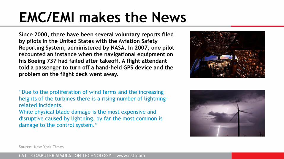
Since 2000, there have been several voluntary reports filed
by pilots in the United States with the Aviation Safety
Reporting System, administered by NASA. In 2007, one pilot
recounted an instance when the navigational equipment on
his Boeing 737 had failed after takeoff. A flight attendant
told a passenger to turn off a hand-held GPS device and the
problem on the flight deck went away.
“Due to the proliferation of wind farms and the increasing
heights of the turbines there is a rising number of lightning-
related incidents.
While physical blade damage is the most expensive and
disruptive caused by lightning, by far the most common is
damage to the control system.”
EMC/EMI makes the News
Source: New York Times

CST – COMPUTER SIMULATION TECHNOLOGY | www.cst.com
“41 medical devices were submitted to 3
EMI tests. A total of 34 EMI incidents were
found; 22 were classified as hazardous
including: total switch-off and change in
rate of ventilators.”
In a recent U.S. government test 4G
wireless service caused interference to 75
percent of global-positioning system
receivers examined. Due to better EMI
filtering techniques cell phone GPS chips
were unaffected.
EMC/EMI makes the News
Source: New York Times, Bloomberg, Forbes

CST – COMPUTER SIMULATION TECHNOLOGY | www.cst.com
The ability of an electrical
system or device to work
satisfactorily in its
electromagnetic environment
without influencing the
surrounding devices (emissions),
or being influenced by the
surrounding equipment
(susceptibility)
Scope of EMC/EMI
KHz Switched Power, Lightning
MHz EMP, HIRF, Radio
GHz Digital electronics, RADAR
EMC
Susceptibility
Environmental Effects (E3)
Emissions

CST – COMPUTER SIMULATION TECHNOLOGY | www.cst.com
Emissions Regulations
Emissions
Radiated and Conducted
North America
FCC Title 47 Part 18
-
Part 15
Part 15
CISPR
11
12
13
14
15
22
25
Europe
EN 55011
-
55013
55014
55015
55022
55025
Description
Industrial, Scientific
Automotive
Broadcast Receivers
House Appliances
Electrical Lighting
ITE
Auto Components
Not all the standards are shown in the table

CST – COMPUTER SIMULATION TECHNOLOGY | www.cst.com
Emissions Problems
EMC design involves minimizing the noise, absorbing the noise, containing the noise (shielding)
and diverting/filtering the noise
Stray fields/couplings/radiation are critical in EMC/EMI!
Often requires full system-level simulation
Coupling between heat sink
and connector bypasses signal
path thru PCB
Coupling through
vent in enclosure
1Slots in ground plane
radiate onto cable, 2DM to
CM current conversion
1 2
Image courtesy of Johnson Controls Inc.

CST – COMPUTER SIMULATION TECHNOLOGY | www.cst.com
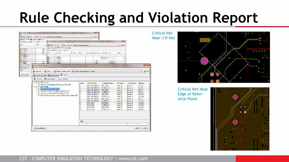
Find Critical Structures on the PCB
1. Deal with a new PCB layout
2. Analyze PCB in EMC rule checker
3. Decide which structures need simulation
4. Perform simulations and analyze results
5. Obtain EMC rules for layout engineers
EMC Rule Checking provides a
smooth, fast workflow from
PCB design to EMC/EMI
simulation
The EMC Rule Check violation
report allows you to focus on
the most critical nets
Design
Cycle
CST BOARDCHECK
CST – COMPUTER SIMULATION TECHNOLOGY | www.cst.com
Rule Checking and Violation Report Critical Net
Near I/O Net
Critical Net Near
Edge of Refer-
ence Plane

CST – COMPUTER SIMULATION TECHNOLOGY | www.cst.com
Emissions Workflow: Cascading
Import from CST BOARDCHECK
Compute transient CM voltage
Simulate radiation from cable
Cascading applied if system can be decoupled

CST – COMPUTER SIMULATION TECHNOLOGY | www.cst.com
Partitioning of Model/USB Channel
Section
1 driver to
choke Section 2 choke to connector
pins
Common Mode Noise
1.5 V without choke
80 mV with choke
Input Differential Signal
Driver skew and imbalance in USB channel leads to CM noise
Section 1 Section 2

CST – COMPUTER SIMULATION TECHNOLOGY | www.cst.com
Radiated Emissions Prediction
Convolution of impulse response with
periodic CM noise
3m emissions scan
Without
CM choke
63 dBμV/m
With
CM choke
34 dBμV/m

CST – COMPUTER SIMULATION TECHNOLOGY | www.cst.com
PCB to Cable Coupling
Transmitted waveform (D+) Received waveform (D+)
Transient co-simulation applied if system cannot be decoupled
Direct coupling from PCB to cable shield may cause emissions problem
CM choke
Flexible
Shielded
Cable Ferrite
bead
500 MHz
pulse train
analysis

CST – COMPUTER SIMULATION TECHNOLOGY | www.cst.com
Cable Radiation
Without
CM choke
With
CM choke
21 dBV/m
-2 dBV/m
Emissions from PCB and cable shield using a
Gaussian pulse excitation (trends analysis)
CM current

CST – COMPUTER SIMULATION TECHNOLOGY | www.cst.com
Emissions Workflow: Near Field Source Near field source enables stray field coupling to be modeled
Solve PCB in Detail and
Export Near Fields
Import Near Fields and
Solve Full System Model
Compact seams and vents

CST – COMPUTER SIMULATION TECHNOLOGY | www.cst.com
Susceptibility Regulations
Susceptibility
Radiated and Conducted
North America
ANSI ESD 20:20
IEC
61000-4-2
61000-4-3
61000-4-4
61000-4-5
61000-4-6
61000-4-8
61000-4-11
Europe
EN 61000-4-2
EN 61000-4-3
EN 61000-4-4
EN 61000-4-5
EN 61000-4-6
EN 61000-4-8
EN 61000-4-11
Description
ESD
Radiated RF
EFT
Surge
Conducted RF
Magnetic fields
Voltage Variations
Not all the standards are shown in the table
CST – COMPUTER SIMULATION TECHNOLOGY | www.cst.com
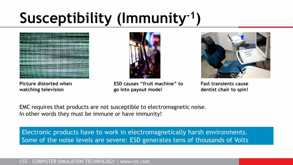
Susceptibility (Immunity-1)
EMC requires that products are not susceptible to electromagnetic noise.
In other words they must be immune or have immunity!
Electronic products have to work in electromagnetically harsh environments.
Some of the noise levels are severe: ESD generates tens of thousands of Volts
ESD causes “fruit machine” to
go into payout mode!
Fast transients cause
dentist chair to spin!
Picture distorted when
watching television

CST – COMPUTER SIMULATION TECHNOLOGY | www.cst.com
Susceptibility Coupling Paths
Power Line (or other interconnecting cables)
1
2 3
4
x
5
Failure criteria depends on the test A No degradation in performance, operates as intended at all times B Degradation allowed during the test, full performance must be restored following the test, without user intervention C Degradation allowed during the test, and after the test, provided that full performance can be restored automatically or by user intervention
Source Victim

CST – COMPUTER SIMULATION TECHNOLOGY | www.cst.com
Automotive EMI Simulation Radiated Susceptibility Simulation
Antenna to Cable Coupling

CST – COMPUTER SIMULATION TECHNOLOGY | www.cst.com
Cable Harness Modeling

CST – COMPUTER SIMULATION TECHNOLOGY | www.cst.com
ESD Simulation of Mobile Phone
A combination of simulations and
measurements allows to identify
soft failures of mobile phones.
Systematic Analysis Methodology for Mobile Phone‘s Electrostatic Discharge Soft Failures;
Ki Hyuk Kim and Yongsup Kim; IEEE Trans. Elec. Comp. Vol.53, No.3, August 2011

CST – COMPUTER SIMULATION TECHNOLOGY | www.cst.com
ESD to Enclosure with Cable Entry
Bi-Directional co-simulation
between the 3D field, cable
and circuit simulations
allows the effect of cable
entry to be considered
External Cable Screen
Bonded to Enclosure
External Cable Screen
not Bonded to Enclosure
CST – COMPUTER SIMULATION TECHNOLOGY | www.cst.com
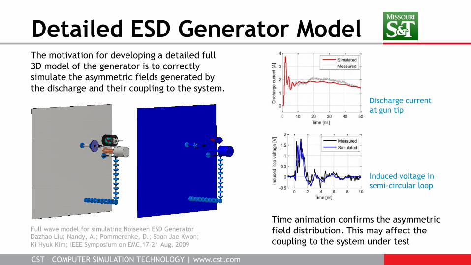
Detailed ESD Generator Model
Full wave model for simulating Noiseken ESD Generator
Dazhao Liu; Nandy, A.; Pommerenke, D.; Soon Jae Kwon;
Ki Hyuk Kim; IEEE Symposium on EMC,17-21 Aug. 2009
The motivation for developing a detailed full
3D model of the generator is to correctly
simulate the asymmetric fields generated by
the discharge and their coupling to the system.
Discharge current
at gun tip
Induced voltage in
semi-circular loop
Time animation confirms the asymmetric
field distribution. This may affect the
coupling to the system under test

CST – COMPUTER SIMULATION TECHNOLOGY | www.cst.com
Hybrid Cable EMI
Programmable switch mode power supply driving an
intelligent sensor with high speed RS485 communications
Interference between SMPS and RS485 circuit
Import measured screen
transfer impedance
Load
SMPS
Sensor
RS485
screen
CST – COMPUTER SIMULATION TECHNOLOGY | www.cst.com
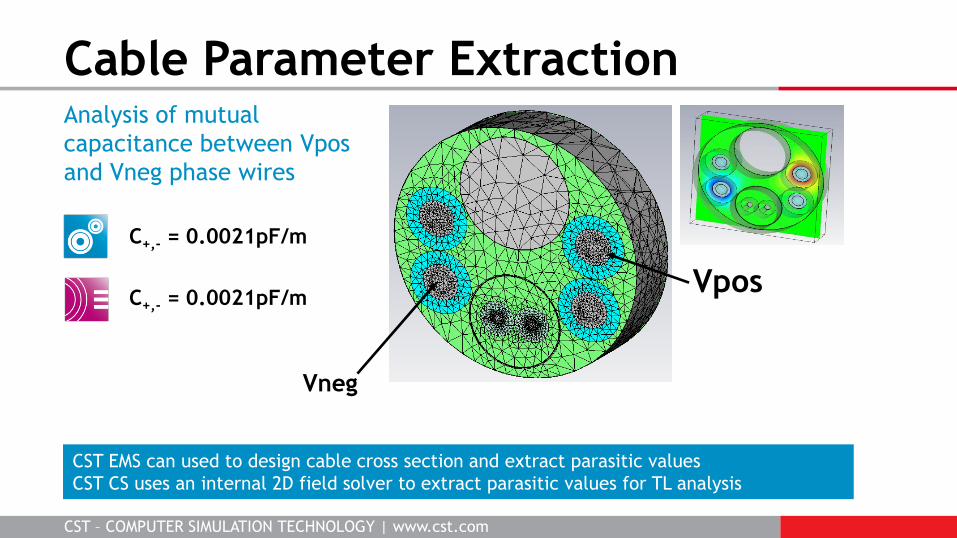
Cable Parameter Extraction
C+,- = 0.0021pF/m
C+,- = 0.0021pF/m
Analysis of mutual
capacitance between Vpos
and Vneg phase wires
Vpos
Vneg
CST EMS can used to design cable cross section and extract parasitic values
CST CS uses an internal 2D field solver to extract parasitic values for TL analysis

CST – COMPUTER SIMULATION TECHNOLOGY | www.cst.com
Interference Analysis
Input SMPS
PWM voltage
CST CS used to investigate CM noise for
different SMPS waveforms, cable
lengths, cable screens and terminations
CM Current in
RS485 line
Cable/circuit co-simulation

CST – COMPUTER SIMULATION TECHNOLOGY | www.cst.com
E3 Regulations
Electromagnetic Environmental Effects
MIL-STD
461/4, 1757
461/4
461, 188-125-1
461/4
1686
ANSI
C63.41
C63.41
C63.14-1992
C95.1-1992
ESD 20:20
RTCA
DO-160F
DO-160G
DO-160F
DO-160C
DO-160D
Description
Lightning
HIRF
EMP
RADHAZ
ESD
Not all the standards are shown in the table

CST – COMPUTER SIMULATION TECHNOLOGY | www.cst.com
E3 Applications
LIGHTNING HIRF EMP
Threat levels can be extremely high: 200kA lightning strike, 50 kV/m EMP, 10kV/m HIRF radiation. Transient
protection required to limit voltage and current levels. Semiconductors are vulnerable to damage by heat.
Lightning and EMP are transient effects, ideal for transient co-simulation
HIRF covers a wide band 10 KHz to 40 GHz – combination of solvers required
Aircraft must not be
susceptible to high intensity
radiated fields
Critical against elesystems
must be hardened
ctromagnetic pulse
Direct or near lightning
strikes can upset or damage
electronic systems

CST – COMPUTER SIMULATION TECHNOLOGY | www.cst.com
Rotorcraft EMP Simulation Important detail such as panel
joints/seams and realistic cables
can be modeled efficiently
Multi-Layer Thin Panel

CST – COMPUTER SIMULATION TECHNOLOGY | www.cst.com
Direct Transient Solution Direct time-domain simulation
of transient effects
MIL-STD 464 Unclassified Waveform

CST – COMPUTER SIMULATION TECHNOLOGY | www.cst.com
EMP Protection Assessment
Non-linear transient protection devices modeled
by true transient co-simulation
Solid and braided screens can be added to
cable model to investigate shielding
True transient co-simulation Real world cable modeling

CST – COMPUTER SIMULATION TECHNOLOGY | www.cst.com
Interference Analysis Powerful workflows for antenna co-site and RADHAZ analysis
CST – COMPUTER SIMULATION TECHNOLOGY | www.cst.com
Complete Solver technology for efficiency
Near Field Source

CST – COMPUTER SIMULATION TECHNOLOGY | www.cst.com
Lightning Strike Simulation Wind turbine lightning analysis
CST – COMPUTER SIMULATION TECHNOLOGY | www.cst.com
Efficient EMC simulation workflows
CST BOARDCHECK identifies potential problem areas for 3D field simulation
Transient solver
Direct time-domain analysis of transients such as ESD, EMP and lightning
Co-simulation
MWS+CS+DS co-simulation enables coupling between fields, cables and circuits
Compact models
Thin conducting panels, slots/gaps, joints/seams and ventilation panels
Realistic cables
Bi-directional coupling between field solution and complex cable models
Conclusions