electromagnetism for haptic interaction with virtual...
TRANSCRIPT
Electromagnetism for Haptic Interaction with Virtual Objects
Kaitlin Lostroscio1
Abstract— Haptic interaction with virtual objects can beenhanced by applying directional forces resembling those ex-perienced when interacting with a physical object. Magnetismis a viable method to achieve these reactional forces. This ex-perimental system combines an electromagnet with a wearablearray of permanent magnets to generate forces which are pairedwith a visual display.
I. INTRODUCTIONIn order to create tactile sensations for virtual interaction,
there are a handful of methodologies which can be applied.Direct force, pressurization, and vibration can all accomplisha sensation of tactile contact, though improvements are stillnecessary to either increase the realism of the experience ormake the system more practical for use. Another approach,which this device takes, is using magnetic fields to generateforces.
The repulsion of two like charges results in a force appliedto surrounding particles. Permanent magnets will exhibitsuch an affect when two magnets are held so that the samepoles face each other. At the macroscopic level, if a magnetis held in one hand while bringing one pole near the poleof another permanent magnet, a force will be exerted ongrasping fingers. Instead of grasping, permanent magnetscould be attached to a wearable glove. Then, performing thetask would create equal-and-opposite forces. The direction ofthese forces would closely resemble the forces experiencedthrough most exploratory procedures. The methodology ishence presumed to have a significant potential for realisticvirtual simulation.
One advantage of using magnetic force is that the sensa-tions can be in free space since the fields can reach awayfrom the magnet itself. Meshing magnetic fields could allowvarious surfaces to be simulated with varying geometries.However, to control the forces when these surfaces are beingexplored and to create changing surfaces, the use of opposingpermanent magnets could be ineffective. Alternatively, theuse of electromagnets could provide a dynamic and anadaptable experience. This is accomplished, in this device, byvarying the output of an electromagnet to adjust the repulsiveforce. Magnitudes could be assigned to particular locationsand the intensity varied depending on the contour of thesurface being simulated. Modulation of the magnetic fieldoutput could aid in simulating harder surfaces. Theoretically,many 3-dimensional shapes could be simulated depending onthe apparatus.
An eventual goal of this technology would be to havewearable electromagnets in a glove so that enclosure of a
1 Kaitlin Lostroscio is a Mechanical Engineering Undergraduate Studentat the University of South Florida.
virtual object could be possible. The strength versus sizecomparison of available electromagnets is the key limitation.As a proof-of-concept, the device described in this paperconstrains user motion and narrows the scope of possiblevirtual objects to be simulated while still demonstrating itsfeasibility. It works to test the efficacy of electromagnetsand permanent magnets to provide realistic forces. In theexperimental scenario, the device is capable of simulatingthe feeling of a ball being dropped in the palm of the hand.
II. RELATED WORK
A. Force Feedback
One method of applying forces to the fingers and hands isthrough direct actuator contact. The FEELEX uses a plane ofactuated pins to generate contours [1]. While the generatedforces can be comparable to real-world haptic experiences,the system lacks portability and the ability to simulateportions of some 3-dimensional objects (i.e. spheres, invertedpyramids, etc.). The CyberGrasp, made by CyberGlove Sys-tems LLC, produces grasp forces by a network of tendonsconnected to the fingers via an exoskeleton [2]. The wearabledevice allows interaction with, and handling of, virtualobjects while also providing force feedback to the user. Eventhough the forces may be delivered to the flexor side of thefinger, the device pulls the fingers from the extensor side. Ifthis type of system is not entirely refined, this style of devicecould restrict active touch. The ability to sense and predictmovement is an involved challenge. The standalone hapticglove with opposing electromagnets, which was proposed inthe introduction, would face a similar challenge. However,the focus of this preliminary design involves a pre-existingvirtual object which can be actively explored.
B. Near Surface Haptics
The other aim of the design in this paper it to allow inter-action with virtual objects in free-space. The CyberGraspaccomplishes this since in consists of a wearable deviceattached to the hands. One other method is through focusedultrasound. The UltraHaptics system requires no contact withtools or physical surfaces and hands are unadorned [3]. Thesystem induces a shear wave in the skin tissue to triggerthe mechanoreceptors and generate a haptic sensation. Anintrinsic benefit is obtaining force feedback in mid-air. Inorder to simulate an object or 3-dimensional surface, thistype of system would require substantial tracking capabilitiesin order to ensure proper force intensities. It also requiresappropriate interaction distances from the system (i.e. thereare some limitations concerning mobility).

C. Magnetic Levitation
Previous works typically involve a tangible object, for auser to interact with directly, that is levitated by magneticfields. Carnegie Mellon University/ Butterfly Haptics LLC,the University of Hawaii-Manoa, and the IBM ThomasJ. Watson Research Center have all developed magneticlevitation devices that involve joystick-like interfaces [4].These devices gain the advantage of have a single movingcomponent for precise and responsive, 6 degrees-of-freedomnear frictionless motion with force and torque feedback(Berkelman & Dzadovsky, 2010). They are dissimilar fromthe proposed device in that the stimuli on the fingers are stillproduced by a physical object.
Other systems, such as the FingerFlux, use arrays of elec-tromagnets along with permanent magnets at the fingertipsto produce attraction, repulsion, vibration, and directionalhaptic feedback [5]. While the principles are similar to theproposed design, the objectives differ. The FingerFlux aimsto assist with guidance for virtual controls, with a focus on 2-dimensional planes. Alternatively, the proposed device aimsto create 3-dimensional virtual surfaces. Possibly one of themore relevant devices is a magnetic field based near surfacehaptic and pointing interface from the National University ofSingapore [6]. It functions primarily as a computer mouseand is capable of attraction, repulsion, and vibration. Thesystem includes an electromagnet array with Hall Effectsensors for tracking the position of fingers. The proposeddevice is not exploring position tracking for the proof-of-concept device, though it could benefit from such techniques.
III. SYSTEM COMPONENTS
A. Visual
An animation of a ball dropping into the palm of a handwas created using trueSpace (Caligari Corporation, version6.6). The hand was obtained from the object library andthe ball was modeled with the settings shown in Figure1. The hand was set at arbitrary coordinates, though sincethe position of the ball is dependent on the object info ofthe hand, these coordinates are presented in Figure 2. Thestarting position of the ball is shown in Figure 3a, andthe ending position in Figure 3b. Gravity was enabled forthe simulation so that the physics of the ball drop wouldbe incorporated automatically by the software. The idealanimation was not obtained for the proof-of-concept system,
Fig. 1: Physical attributes of the animated ball.
Fig. 2: Coordinates of the virtual hand throughout the dura-tion of the animation.
but the visual created was still sufficient for pairing with thehaptic feedback. The animation rendered in trueSpace andthen was imported into Sony Vegas where the timed lengthof the ball being stationary in the hand was adjusted. Alsothe clip was copied, reversed, and sped up, then added afterthe original clip for the ball to appear to be lifted up quicklyat the end of the video. This produced a visual for whenthe haptic feedback is disabled. An appropriate backgroundwas also added which worked to blend into the potentialsurrounding test environment. Finally, a short audio clip wasplaced as further described in the hardware section. Thisvideo was played on a laptop during each simulation. Figure4 shows a screen shot of the video.
The test apparatus also included a light-weight cylinder ontop of the platform that the user places a hand under, furtherdescribed in Experimental Setup. This cylinder was there fora psychological aspect of the experimental setup. It providesa location where a ball could be falling. If there were openspace in view of the user, then the haptic effect may beconsidered unrealistic due to lack of visual comparison. Analternative could be to have users close their eyes. However,since an application for this system would be with virtualreality, testing with a visual component was deemed moreappropriate.
(a) Starting Position
(b) Ending Position
Fig. 3: Coordinates of the ball at the beginning (a) and end(b) of the animation.

Fig. 4: Frame from the video played during the hapticsimulation.
B. Hardware
An Arduino MEGA 2650 was used to store a programand indirectly control an electromagnet. The electromagnetwas a modified microwave transformer. For the purposes ofthis system, it was desired to operate at 12V, 3A minimum.A substantial force was observed in preliminary testing withapproximately one inch between a small, permanent magnetand the electromagnet at these conditions.
In order to power the electromagnet to the desired mag-nitude, the microcontroller output current needed to beamplified from 12.5mA to 5A. This was accomplished usinga Darlington Pair configuration of 2N3055 transistors (withcurrent gains of 20 minimum), as show in Figure 5, wherethe current is first amplified from 12.5mA to 250mA andthen to 5A. The load carrying transistor (2nd stage of theDarlington) is protected by a diode. This system could bereplaced with a MOSFET (with TTL), or other appropriatecontroller, if it is able handle an inductive load and have apower supply rating of at least 5A at 12V. Figure 5 shows a
Fig. 5: Schematic for the system power control.
Fig. 6: Full hardware setup including Arduino MEGA 2650,power control subsystem, DTMF decoder subsystem, and12V battery.
schematic of the power control.In order to synchronize the video with the haptic feedback,
another subsystem was used. It involves a dual-tone multi-frequency (DTMF) decoder paired with a relay so thatan output is activated when a certain tone combination isprovided as an input to this subsystem. The output in thiscase, is to the microcontroller. Then, the tone was placeda frame before the ball touches the hand in the animationvideo. Therefore, connecting to the headphone jack of thecomputer to this subsystem allows activation of the ArduinoMEGA (and triggers the code) when the tone is issued.Figure 6 shows each hardware component along with the12V power supply.
C. Code
The time that the simulated ball was to contact the handwas found using a mathematical model for a ball bounce [7].This model incorporates the coefficient of restitution for theball. It was hence, an appropriate input which could be variedto create the desired haptic effect. Since the human hand alsohas a certain magnitude of elasticity, the value assigned wasnot necessarily based on a ball of a particular material, butrather was adjusted until the desired haptic effect and decayof bounce were obtained. The mathematical model providedan expression for the duration of the bounce cycle at anyinstance. The equation incorporated in initial velocity. Sincethe intention for this test of this system was to begin witha ball falling from rest, the equation was adapted to be afunction of starting height instead of initial velocity:
tb = ri/2p
8 ⇤ h/g (1)
where tb is the time (in seconds) at each iteration “i”, ris the coefficient of restitution for the ball, h is the heightfrom which the ball is dropped, and g is the acceleration offreefall.
This quantity of time was used in the program to definethe time between bounces, rather than the time of contactfor each bounce. In this way, the simulated contact timewould remain the same for each bounce and would feel morerealistic. Therefore, the duration that the electromagnet was
powered remained constant, at 100ms, and only the timebetween powering would shorten.
An exit condition exists from the source of the mathemat-ical model. However, using a constant value proved morereasonable for experimental adjustments. Therefore, the timeat 100 bounces was calculated and set as the limit for theminimum time originally (this was later reduced, with thefinal value presented in the Results). This way, the maximumdesirable bounce frequency could be set to generate a morenatural feeling effect for a ball bouncing in the palm of thehand. This limit was adjusted during testing as well. Oncethe limit was reached, a constant output was enabled for theelectromagnet (i.e. the ball resting in the palm of the hand).It would turn off after 2 seconds and the virtual ball wouldlift as was described in the Visual section.
The intensity of the magnetic field was set in the ArduinoIDE using analogWrite() from 0 to 255. Proposed settingsare provided in the results.
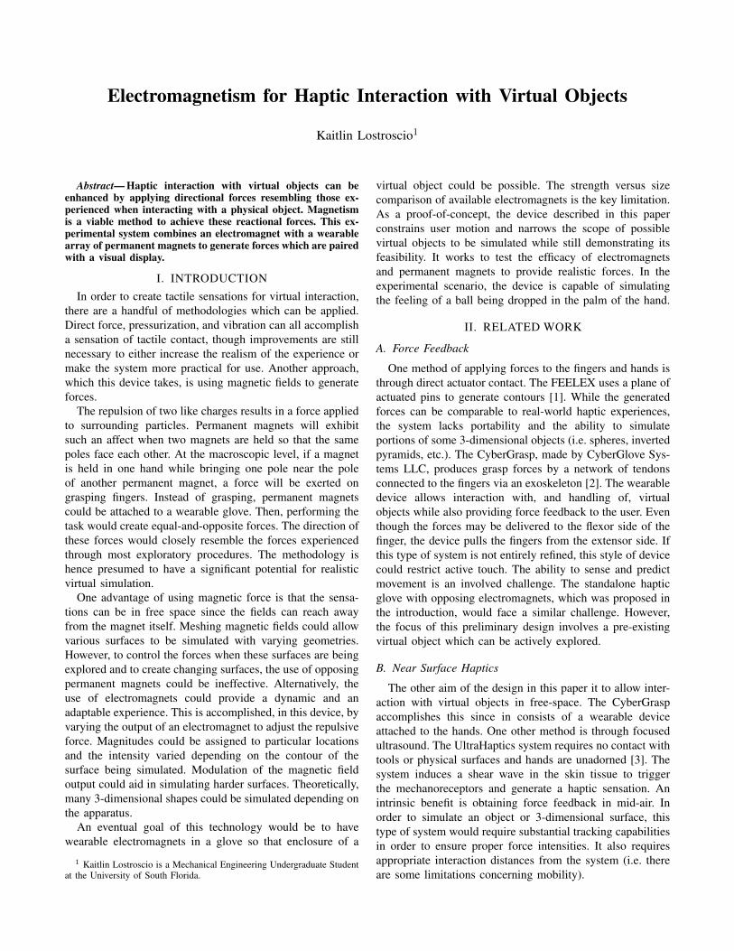
IV. EXPERIMENTAL SETUPA small pad containing 3 small, permanent neodymium
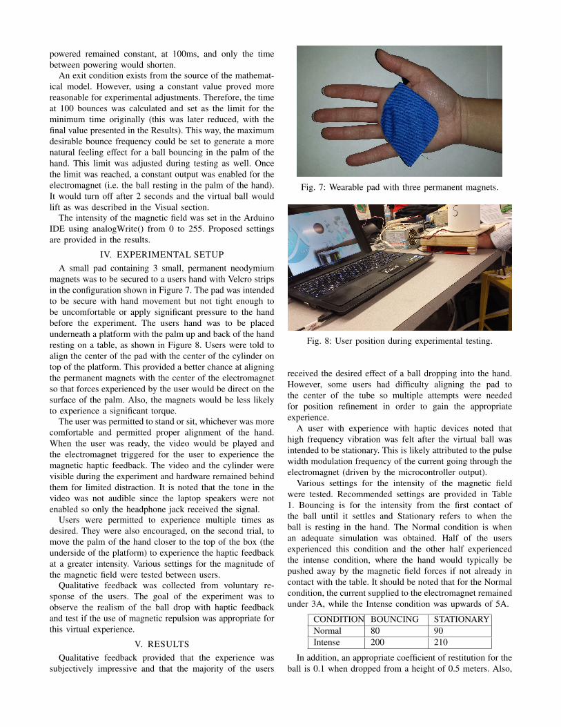
magnets was to be secured to a users hand with Velcro stripsin the configuration shown in Figure 7. The pad was intendedto be secure with hand movement but not tight enough tobe uncomfortable or apply significant pressure to the handbefore the experiment. The users hand was to be placedunderneath a platform with the palm up and back of the handresting on a table, as shown in Figure 8. Users were told toalign the center of the pad with the center of the cylinder ontop of the platform. This provided a better chance at aligningthe permanent magnets with the center of the electromagnetso that forces experienced by the user would be direct on thesurface of the palm. Also, the magnets would be less likelyto experience a significant torque.
The user was permitted to stand or sit, whichever was morecomfortable and permitted proper alignment of the hand.When the user was ready, the video would be played andthe electromagnet triggered for the user to experience themagnetic haptic feedback. The video and the cylinder werevisible during the experiment and hardware remained behindthem for limited distraction. It is noted that the tone in thevideo was not audible since the laptop speakers were notenabled so only the headphone jack received the signal.
Users were permitted to experience multiple times asdesired. They were also encouraged, on the second trial, tomove the palm of the hand closer to the top of the box (theunderside of the platform) to experience the haptic feedbackat a greater intensity. Various settings for the magnitude ofthe magnetic field were tested between users.
Qualitative feedback was collected from voluntary re-sponse of the users. The goal of the experiment was toobserve the realism of the ball drop with haptic feedbackand test if the use of magnetic repulsion was appropriate forthis virtual experience.
V. RESULTSQualitative feedback provided that the experience was
subjectively impressive and that the majority of the users
Fig. 7: Wearable pad with three permanent magnets.
Fig. 8: User position during experimental testing.
received the desired effect of a ball dropping into the hand.However, some users had difficulty aligning the pad tothe center of the tube so multiple attempts were neededfor position refinement in order to gain the appropriateexperience.
A user with experience with haptic devices noted thathigh frequency vibration was felt after the virtual ball wasintended to be stationary. This is likely attributed to the pulsewidth modulation frequency of the current going through theelectromagnet (driven by the microcontroller output).
Various settings for the intensity of the magnetic fieldwere tested. Recommended settings are provided in Table1. Bouncing is for the intensity from the first contact ofthe ball until it settles and Stationary refers to when theball is resting in the hand. The Normal condition is whenan adequate simulation was obtained. Half of the usersexperienced this condition and the other half experiencedthe intense condition, where the hand would typically bepushed away by the magnetic field forces if not already incontact with the table. It should be noted that for the Normalcondition, the current supplied to the electromagnet remainedunder 3A, while the Intense condition was upwards of 5A.
CONDITION BOUNCING STATIONARYNormal 80 90Intense 200 210
In addition, an appropriate coefficient of restitution for theball is 0.1 when dropped from a height of 0.5 meters. Also,

an appropriate limit to the time that should be reached, byEquation 1, before the ball rests is 0.0008 seconds.
VI. FUTURE WORKDifferent experiments are possible with the same test
apparatus. This system could be used to simulate a ping-pongball dropping on a paddle or similar ball sport. A glove couldreplace the pad, or the method of connecting the permanentmagnets to the pad could be made more flexible, in order topermit haptic exploration of a stationary ball.
Another concept desired to be tested is using an array ofelectromagnets set at various intensities so that virtual 3-dimensional surfaces can be simulated.
As stated in the introduction, an eventual goal of thistechnology would be to have wearable electromagnets in aglove so that enclosure of a virtual object could be possible.This way, the experience can truely be in free space and notunder the constraints of a box.
VII. CONCLUSIONThis proof-of-concept system demonstrated that magnetic
fields are appropriate for generating forces for a simplifiedhaptic simulation. In the scenario of a ball drop, the station-ary apparatus, where the user had only limited restriction ofthe hand, the haptic simulation seemed to be accepted bythe users. The system can be expanded to incorporate othersimulations and can also be improved for a more mobileexperience.
APPENDIX
/ / Ardu ino Code f o r B a l l Drop
void s e t u p ( ){/ / i n i t i a l i z e d i g i t a l p i n as an o u t p u t/ / e n a b l e on board LED/ / ( t o be a v i s u a l i n d i c a t o r o fe l e c t r o m a g n e t f u n c t i o n i n g )pinMode ( 1 3 ,OUTPUT ) ;
/ / s e t u p p i n f o r i n p u t/ / ( r e a d i n g t o n e g e n e r a t o r r e l a y )pinMode ( 3 1 , INPUT PULLUP ) ;}
/ / s i g n a l t o e l e c t r o m a g n e t i n p i n 11/ / 31 t o 53 ( e n a b l e l i m i t s w i t c h c o n t r o l )/ / 3A @ 100 and 5A a t 200
/ / i n i t i a l i z e c o u n tdouble i = 0 ;/ / s e t r e s t i t u t i o n f a c t o r f o r b a l l m a t e r i a l/ / ( i n c o m b i n a t i o n w i t h hand )double r = 0 . 1 ;/ / s e t i n i t i a l h e i g h t o f b a l l drop (m)double h = 0 . 5 ;
/ / a c c e l e r a t i o n o f f r e e f a l l on p l a n e tdouble g = 9 . 8 1 ;/ / t i m e t h e b a l l i s n o t i n c o n t a c tf o r each bouncedouble t b ;
/ / For t r i g g e r i n g program ( and l a t c h i n g )i n t k = 0 ;i n t p i n v a l ;
void l oop ( ){
p i n v a l = d i g i t a l R e a d ( 3 1 ) ;i f ( p i n v a l ==0 | | k ==1){
k = 1 ;i = i + 1 . 0 ;t b = pow ( r , i / 2 ) ⇤ s q r t (8⇤ h / g ) ;
i f ( tb >0.0008){/ / S e t i n t e n s i t y f o r t h em a g n e t i c f i e l d/ / p in , magni tude (0 � 255)a n a l o g W r i t e ( 1 1 , 2 0 0 ) ;d e l a y ( 1 0 0 ) ;d i g i t a l W r i t e ( 1 3 ,HIGH ) ;a n a l o g W r i t e ( 1 1 , 0 ) ;d e l a y ( ( i n t ) ( 1 0 0 0⇤ t b ) ) ;d i g i t a l W r i t e ( 1 3 ,LOW) ;
}e l s e {
a n a l o g W r i t e ( 1 1 , 2 1 0 ) ;d i g i t a l W r i t e ( 1 3 ,HIGH ) ;d e l a y ( 2 0 0 0 ) ;a n a l o g W r i t e ( 1 1 , 0 ) ;d i g i t a l W r i t e ( 1 3 ,LOW) ;k = 0 ;i = 0 ;
}}
}
REFERENCES
[1] Iwata, Hiroo, et al. ”Project FEELEX: adding haptic surface tographics.”Proceedings of the 28th annual conference on Computergraphics and interactive techniques. ACM, 2001.
[2] ”CyberGrasp.” CyberGlove Systems LLC. Web. 25 Nov. 2015.http://www.cyberglovesystems.com/cybergrasp/.
[3] Carter, Tom, et al. ”Ultrahaptics: multi-point mid-air haptic feedbackfor touch surfaces.” Proceedings of the 26th annual ACM symposiumon User interface software and technology. ACM, 2013.
[4] Berkelman, Peter, and Michael Dzadovsky. Using Magnetic Levitationfor Haptic Interaction. INTECH Open Access Publisher, 2010.
[5] Weiss, Malte, et al. ”FingerFlux: near-surface haptic feedback ontabletops.”Proceedings of the 24th annual ACM symposium on Userinterface software and technology. ACM, 2011.
[6] Karunanayaka, Kasun, et al. ”Magnetic field based near surface hap-tic and pointing interface.” Human-Computer Interaction. InteractionModalities and Techniques. Springer Berlin Heidelberg, 2013. 601-609.

[7] Feucht, Jonathan A. ”Developing a Mathematical Model.” TheMystery of the Bouncing Ball. N.p., 2011. Web. 29 Nov. 2015.http://feucht.us/writings/bouncingball.php.