electronic jet kit instructions - zodiac · 2016-02-10 · electronic jet kit instructions 1. after...
TRANSCRIPT
Rev 1.0.0 1440ST TFI Patent Number: 7,000,599 10/4/2006 2:37 PM
Dobeck Performance Phone: 877-764-3337 Email [email protected]
401 Jackrabbit Lane Belgrade, MT 59714 Fax: 406-388-2455 Site: www.dobeckperformance.com
1
Electronic Jet Kit� Instructions
IINNSSTTAALLLLAATTIIOONN PPRREEPP
��Install Time: 60 minutes ��Required Tools for: Disconnecting the negative terminal of the battery
Removing your seat Loosening and propping up the fuel tank
Thank you for choosing the Techlusion Electronic Jet Kit, the TFI. The TFI is only usable for the following Harley Davidson models:
��2007 DYNA ��2007 SOFTAIL ��2007 TOURING
This product is a great fit for stock bikes with exhaust and intake mods. This is an Electronic Jet Kit. Like jet kits in the past, the more you modify, the more responsibility you take in getting your fuel curve right. Going to www.dobeckperformance.com will help you obtain better high horsepower tuning.
Some vehicle modifications with Techlusion Inc. productsmust not be used on public roads and in some cases maybe restricted to close course competition. Those products not identified as US EPA legal are intended for off-road or marine applications only. Not intended for use on emission controlled vehicles.

Rev 1.0.0 1440ST TFI 10/4/2006 2:37 PM
Dobeck Performance Phone: 877-764-3337 Email [email protected]
401 Jackrabbit Lane Belgrade, MT 59714 Fax: 406-388-2455 Site: www.dobeckperformance.com
2
Electronic Jet Kit� Instructions
1. Before installing the TFI you must first disconnect the negative lead from the battery. 2. Determine a location for the TFI unit. Suggested locations are as follows:
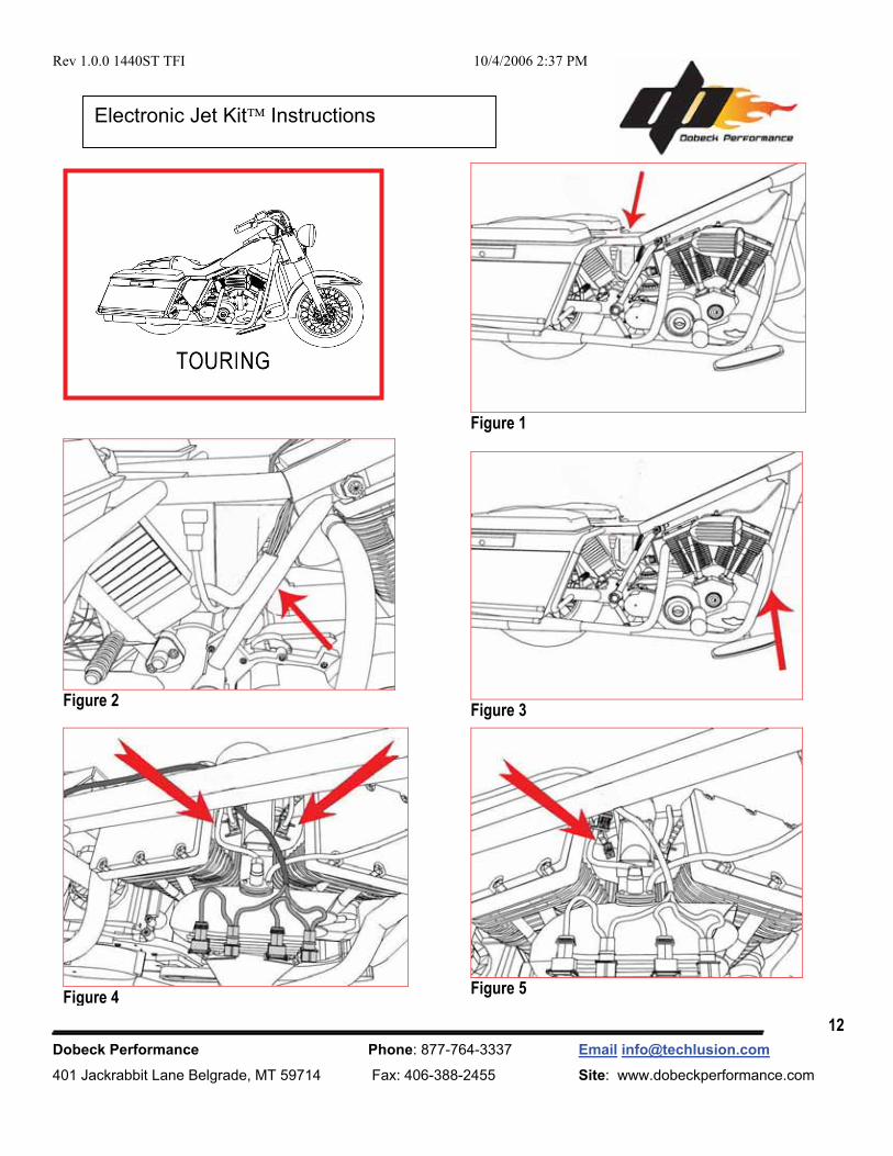
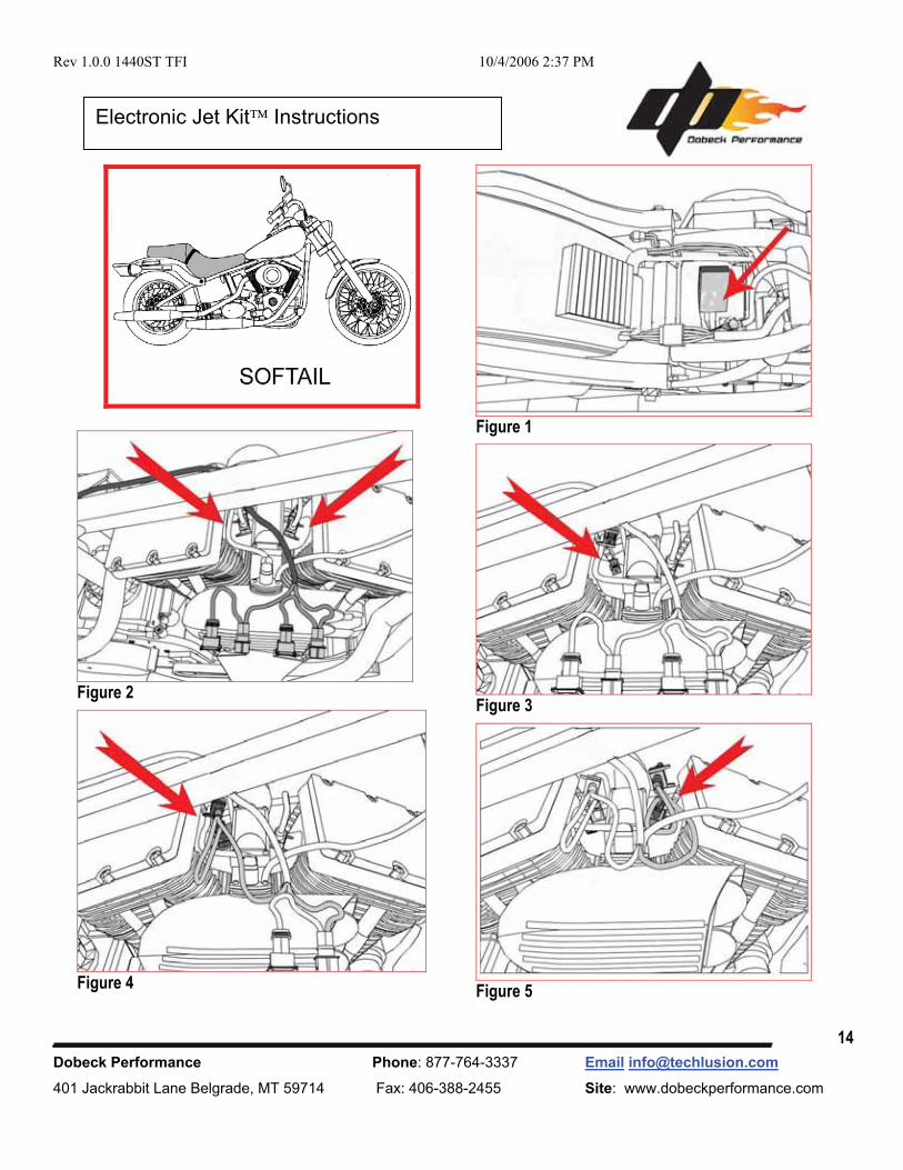
DYNA – see figure 2 - Under seat, inside large frame opening TOURING – see figure 1 - Under seat, inside small frame opening SOFTAIL – see figure 1 - Under seat, on top of battery
3. Make sure your motorcycle is cold, locate and disconnect the fuel line under the left hand side of the fuel tank using the quick disconnect feature on the fuel fitting (DO NOT UNSCREW THE FITTING). Remove the rear fuel tank mounting bolt and slowly lift up the fuel tank (make sure the fuel tank does not come in contact with steering area). You will need something to hold the fuel tank up (block of wood or a towel) from the frame to gain access to the injectors.
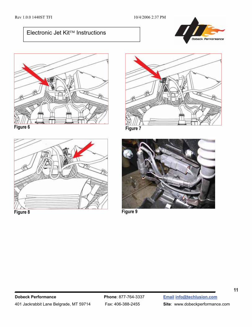
4. Underneath the fuel tank you will locate the fuel injectors (DYNA figure 5, TOURING figure 4, SOFTAIL figure 2). 5. Disconnect the factory fuel injector connector from the fuel injector. Connect the TFI fuel injector harness inline with the
factory fuel injector connector and the factory fuel injector. Reference following figures: (DYNA- figures 6,7,8) (TOURING- figures 5,6,7) (SOFTAIL- figures 3,4,5) IMPORTANT: The TFI injector harness with the white/yellow wires must go to the front cylinder. The TFI injector harness with the green/gray wires must go to the rear cylinder. We recommend the TFI injector harness run along the left side of the frame backbone to the injectors along with the front TFI O2 harness (long harness with pink/tan wires). IMPORTANT: Make sure all connections are firmly secure and allow a little slack at the connections to prevent engine vibration from damaging/breaking a wire on the harness.
6. The front factory O2 connector is located in between the front down tubes of the frame just behind the front tire (DYNA figure 3, TOURING figure 3, SOFTAIL figure 6). The front TFI O2 harness (long harness with pink/tan wires) will run along the left side of the frame down to the front factory O2 connector.
DYNA and SOFTAIL - O2 connector is actually located behind the voltage regulator assembly inside a plastic connector caddy attached to the backside of the voltage regulator. You will need to remove the voltage regulator to gain access to the plastic connector caddy and the factory front O2 connector. TOURING - O2 connector is zip tied to the cross member/down tube area on the front portion of the frame.
Once you have gained access to the front factory O2 harness for your model, connect the front TFI O2 harness (long harness with pink/tan wires) inline with the factory O2 connector and secure. IMPORTANT: Make sure connection is firmly secure and allow a little slack at the connection to prevent engine vibration from damaging/breaking a wire on the harness.
7. The rear factory O2 connector is located: DYNA – figure 4 - Under the seat, inside the frame opening. TOURING – figure 2 - Follow the O2 harness from the rear head pipe down to the starter. SOFTAIL - figure 7 - Under the oil tank on the right hand side.
Once you have gained access to the factory rear O2 harness for your model, connect the rear TFI O2 harness (short harness with purple wires) inline with the factory O2 harness then secure. IMPORTANT: Make sure connection is firmly secure and allow a little slack at the connection to prevent engine vibration from damaging/breaking a wire on the harness.
8. Replace the fuel tank (make sure all mounting bolts are in place and fuel connections are correct). 9. Connect the TFI ground lead to the negative terminal of the battery along with the factory ground lead.

Rev 1.0.0 1440ST TFI 10/4/2006 2:37 PM
Dobeck Performance Phone: 877-764-3337 Email [email protected]
401 Jackrabbit Lane Belgrade, MT 59714 Fax: 406-388-2455 Site: www.dobeckperformance.com
3
Electronic Jet Kit� Instructions
1. After connecting the box, check all wire connections to ensure proper connection. Do this by pulling on the connection to
make sure the connectors are properly locked in.
2. Be sure to check the wire harnesses are not in direct contact with any sharp edges, exhaust and/or other objects, which could result in long term wear and/or damage.
3. Start the bike up. In approximately five seconds, the lights inside the TFI will energize and become visible. With a
proper installation, the TFI will have a continuous lighting sequence where green lights come on from left to right and then back again. Sequence repeats until the bike is fully warmed up. It will then stop scrolling the lights and go to a steady green light to the far left and “MAY” have a flashing blue light to the far right. With an improper installation the light display will consist of a flashing green and a flashing red light. This occurs when the TFI is not receiving a proper injector signal. Recheck the wire connections for any defects. (The flashing green and flashing red lights is common for a proper installation during deceleration because the stock fuel map shuts off the fuel injectors during this process.)
4. At this point you are ready to adjust the TFI to the base settings supplied with the unit. The first thing to do is ensure the
proper code was supplied by checking that the six programmable features are available. To begin this process press the MODE button and to enter each successive mode, just press the MODE button again. The unit comes with pre-programmed base settings which should match the recommended starting settings on pg 8.
a. The first mode represents an additional amount of fuel added during light load steady throttle cruise/idle. A
flashing green light should appear somewhere on the light display. b. The second mode represents an additional amount of fuel added during acceleration. A flashing yellow light
should appear somewhere on the light display. c. The third mode represents an additional amount of fuel added during full throttle. A flashing red light should
appear somewhere on the light display. d. The fourth mode represents an adjustment for richening the de-acceleration fuel mixture. A flashing green light
should appear somewhere on the light display along with a flashing blue light on the very right side. e. The fifth mode represents an adjustment for when the yellow fuel engages. A flashing yellow light should
appear somewhere on the light display along with a flashing blue light on the very right side. f. The sixth mode represents an adjustment for when the red fuel engages. A flashing red light should appear
somewhere on the light display along with a flashing blue light on the very right side.

Rev 1.0.0 1440ST TFI 10/4/2006 2:37 PM
Dobeck Performance Phone: 877-764-3337 Email [email protected]
401 Jackrabbit Lane Belgrade, MT 59714 Fax: 406-388-2455 Site: www.dobeckperformance.com
4
Electronic Jet Kit� Instructions
If each mode is present then the proper code exists and you are ready for making manual adjustments. If you failed to enter a mode, try going through the sequence again and be sure to only press the MODE button once in between each step.
5. You are now ready to manually program each mode. Consult the base settings supplied with the unit or you can look up
the most up-to-date settings by going to www.dobeckperformance.com.
To program the TFI, the bike must be running in order to supply power to the box. If at anytime you stay in an adjusting mode for longer than 5 seconds without pressing any buttons, the TFI will exit adjusting mode and will return to the ready state. To save settings for a particular mode, press the MODE button which goes to the next adjustable mode or wait for the TFI to exit back to the ready state.
The settings are adjusted by pressing the PLUS and MINUS buttons located on the right and left side respectively of the MODE button. To start adjusting, first press the MODE button the desired amount of times to reach the mode you wish to adjust. Pressing the PLUS button signifies an increase of 0.5 for the mode setting. Similarly, pressing the MINUS button signifies a decrease of 0.5 for the mode setting. The range of settings for each mode is 0 to 8. Light settings of 0 or 0.5 are essentially the same and are displayed by the very left light blinking at a faster rate than normal. When entering into green/blue, yellow/blue, or red/blue modes, a flashing blue light will appear on the very right. For light settings of 7.5 and 8 within these modes, the very right light will flash back and forth between the respective mode’s color and blue. To see a visual display of adjusting settings go online to dobeckperformance.com
6. Your TFI should now be properly programmed and you are now ready to tune your bike.
Always make sure your bike is at normal operating temperature when making tuning adjustments.

Rev 1.0.0 1440ST TFI 10/4/2006 2:37 PM
Dobeck Performance Phone: 877-764-3337 Email [email protected]
401 Jackrabbit Lane Belgrade, MT 59714 Fax: 406-388-2455 Site: www.dobeckperformance.com
5
Electronic Jet Kit� Instructions
Tuning for mode 1 – Fuel addition during steady throttle cruise/idle.
This adjustment deals with adding fuel during all steady throttle/idle conditions. The lowest light setting (0) represents the factory fuel addition level and the highest light setting (8) represents the maximum amount of TFI fuel added to the factory level.
Tuning for mode 2 – Fuel addition during acceleration
Tuning for this mode depends greatly upon your individual bike and can vary widely from the base setting. After market high flow exhaust systems and high flow air filters “MAY” cause you to tune differently from the base settings. This combination could have a setting difference as great as three yellow lights. Note that this adjustment is only for hard acceleration. The lowest light setting (0) represents the factory fuel addition level and the highest light setting (8) represents the maximum amount of TFI fuel added to the factory level.
Tuning for mode 3 – Fuel addition during full throttle
This adjustment deals with adding fuel for primarily 4000 RPM and up to red line. For example, running to red line in 1st, shifting, running to red line in 2nd, shifting, and continuing this all the way through the gear range, you would have been engaging the red light all the time. Again this mode could vary widely from the base settings depending on the set up of your bike and could have a difference as great as three red lights or more. The lowest light setting (0) represents the factory fuel addition level and the highest light setting (8) represents the maximum amount of TFI fuel added to the factory level.
Tuning for mode 4 – Represents an adjustment for richening the de-acceleration mixture This adjustment deals with enrichening the de-acceleration fuel. The lowest light setting (0) represents the factory fuel addition level and the highest light setting (8) represents the maximum amount of TFI fuel added to the factory level.
Tuning for mode 5 – Represents an adjustment for when the yellow fuel engages
This mode “MAY” vary from the base settings depending on the set up of your bike. The lowest light setting (0) represents the lightest load to switch on the yellow fuel and the highest light setting (8) represents the heaviest load to switch on the yellow fuel.
Tuning for mode 6 – Represents an adjustment for when the red fuel engages
The base setting for this mode will rarely have to be changed. The red light should be engaged during the full throttle period. For example, running to red line in 1st, shifting, running to red line in 2nd, shifting, and continuing this all the way through the gear range, the red light should be engaged the whole time. If you do not see the red light the whole time then you need to lower this setting to make the red light turn on sooner.

Rev 1.0.0 1440ST TFI 10/4/2006 2:37 PM
Dobeck Performance Phone: 877-764-3337 Email [email protected]
401 Jackrabbit Lane Belgrade, MT 59714 Fax: 406-388-2455 Site: www.dobeckperformance.com
6
Electronic Jet Kit� Instructions
Start-Up Light Sequence
General Layout
TFI Instructions

Rev 1.0.0 1440ST TFI 10/4/2006 2:37 PM
Dobeck Performance Phone: 877-764-3337 Email [email protected]
401 Jackrabbit Lane Belgrade, MT 59714 Fax: 406-388-2455 Site: www.dobeckperformance.com
7
Electronic Jet Kit� Instructions
Mode 1 – Green
Mode 2 – Yellow
Mode 3 – Red
Mode 4 – Green/ Blue
Adjustment Modes
Mode 5 – Yellow/Blue
Mode 6- Red/Blue

Rev 1.0.0 1440ST TFI 10/4/2006 2:37 PM
Dobeck Performance Phone: 877-764-3337 Email [email protected]
401 Jackrabbit Lane Belgrade, MT 59714 Fax: 406-388-2455 Site: www.dobeckperformance.com
8
Electronic Jet Kit� Instructions
Mode 1 Mode 2
Mode 3
2007 (96 inch) Base Settings
Mode 4
Mode 5 Mode 6

Rev 1.0.0 1440ST TFI 10/4/2006 2:37 PM
Dobeck Performance Phone: 877-764-3337 Email [email protected]
401 Jackrabbit Lane Belgrade, MT 59714 Fax: 406-388-2455 Site: www.dobeckperformance.com
9
Electronic Jet Kit� Instructions
Mode 1
Mode 3
Mode 5
Mode 2
Mode 4
Mode 6
2007 (96 inch) Stage 1 Settings

Rev 1.0.0 1440ST TFI 10/4/2006 2:37 PM
Dobeck Performance Phone: 877-764-3337 Email [email protected]
401 Jackrabbit Lane Belgrade, MT 59714 Fax: 406-388-2455 Site: www.dobeckperformance.com
10
Electronic Jet Kit� Instructions
Figure 1
Figure 2
Figure 3
Figure 4
Figure 5
Rev 1.0.0 1440ST TFI 10/4/2006 2:37 PM
Dobeck Performance Phone: 877-764-3337 Email [email protected]
401 Jackrabbit Lane Belgrade, MT 59714 Fax: 406-388-2455 Site: www.dobeckperformance.com
11
Electronic Jet Kit� Instructions
Figure 8
Figure 7
Figure 9
Figure 6
Rev 1.0.0 1440ST TFI 10/4/2006 2:37 PM
Dobeck Performance Phone: 877-764-3337 Email [email protected]
401 Jackrabbit Lane Belgrade, MT 59714 Fax: 406-388-2455 Site: www.dobeckperformance.com
12
Electronic Jet Kit� Instructions
Figure 1
Figure 2
Figure 3
Figure 4
Figure 5

Rev 1.0.0 1440ST TFI 10/4/2006 2:37 PM
Dobeck Performance Phone: 877-764-3337 Email [email protected]
401 Jackrabbit Lane Belgrade, MT 59714 Fax: 406-388-2455 Site: www.dobeckperformance.com
13
Electronic Jet Kit� Instructions
Figure 6
Figure 7
Rev 1.0.0 1440ST TFI 10/4/2006 2:37 PM
Dobeck Performance Phone: 877-764-3337 Email [email protected]
401 Jackrabbit Lane Belgrade, MT 59714 Fax: 406-388-2455 Site: www.dobeckperformance.com
14
Electronic Jet Kit� Instructions
Figure 1
Figure 2
Figure 3
Figure 4
Figure 5

Rev 1.0.0 1440ST TFI 10/4/2006 2:37 PM
Dobeck Performance Phone: 877-764-3337 Email [email protected]
401 Jackrabbit Lane Belgrade, MT 59714 Fax: 406-388-2455 Site: www.dobeckperformance.com
15
Electronic Jet Kit� Instructions
Figure 6
Figure 7

Rev 1.0.0 1440ST TFI 10/4/2006 2:37 PM
Dobeck Performance Phone: 877-764-3337 Email [email protected]
401 Jackrabbit Lane Belgrade, MT 59714 Fax: 406-388-2455 Site: www.dobeckperformance.com
16
Electronic Jet Kit� Instructions
Notes:

Rev 1.0.0 1440ST TFI 10/4/2006 2:37 PM
Dobeck Performance Phone: 877-764-3337 Email [email protected]
401 Jackrabbit Lane Belgrade, MT 59714 Fax: 406-388-2455 Site: www.dobeckperformance.com
17
Electronic Jet Kit� Instructions
2-Year Unlimited Mileage Warranty Techlusion warrants that this product carries a warranty for 2 years from date of purchase against original defects in materials and workmanship. Should this product fail to perform for either of the above reasons, Techlusion will repair or replace it with an equivalent product at no charge, except for postage, to the original retail purchaser.
* * Important * * Important * *To obtain the benefits of this warranty, the retail purchaser must send the product with proof of purchase and postage prepaid to:
Dobeck Performance 401 Jackrabbit Lane Belgrade, MT 59714
Phone 877-764-3337 or email [email protected]