electronic supplementary information€ electronic supplementary information vincent chan a,e, ......
TRANSCRIPT

†ELECTRONIC SUPPLEMENTARY INFORMATION
Vincent Chana,e, Jae Hyun Jeongb, Piyush Bajaja,e, Mitchell Collensa,e, Taher Saifd, Hyunjoon Kongb, Rashid
Bashira,c,e,*
aDepartment of Bioengineering,
bDepartment of Chemical and Biomolecular Engineering,
cDepartment
of Electrical and Computer Engineering, dDepartment of Mechanical Engineering,
eMicro and
Nanotechnology Laboratory, University of Illinois at Urbana-Champaign, Urbana, Illinois 61801 USA
Electronic Supplementary Material (ESI) for Lab on a ChipThis journal is © The Royal Society of Chemistry 2011
†ELECTRONIC SUPPLEMENTARY INFORMATION
Supplementary Text
Cantilever bending due to non-uniform stress gradient
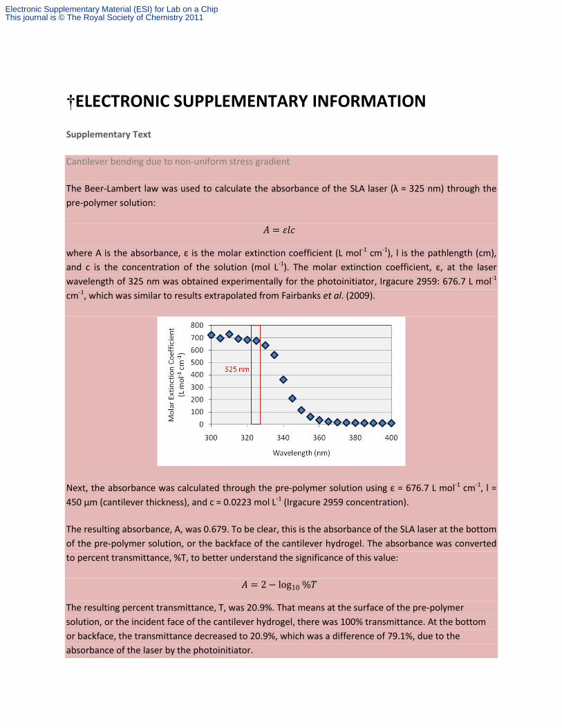
The Beer-Lambert law was used to calculate the absorbance of the SLA laser (λ = 325 nm) through the
pre-polymer solution:
𝐴 = 𝜀𝑙𝑐
where A is the absorbance, ε is the molar extinction coefficient (L mol-1 cm-1), l is the pathlength (cm),
and c is the concentration of the solution (mol L-1). The molar extinction coefficient, ε, at the laser
wavelength of 325 nm was obtained experimentally for the photoinitiator, Irgacure 2959: 676.7 L mol-1
cm-1, which was similar to results extrapolated from Fairbanks et al. (2009).
Next, the absorbance was calculated through the pre-polymer solution using ε = 676.7 L mol-1 cm-1, l =
450 µm (cantilever thickness), and c = 0.0223 mol L-1 (Irgacure 2959 concentration).
The resulting absorbance, A, was 0.679. To be clear, this is the absorbance of the SLA laser at the bottom
of the pre-polymer solution, or the backface of the cantilever hydrogel. The absorbance was converted
to percent transmittance, %T, to better understand the significance of this value:
𝐴 = 2− log10%𝑇
The resulting percent transmittance, T, was 20.9%. That means at the surface of the pre-polymer
solution, or the incident face of the cantilever hydrogel, there was 100% transmittance. At the bottom
or backface, the transmittance decreased to 20.9%, which was a difference of 79.1%, due to the
absorbance of the laser by the photoinitiator.
Electronic Supplementary Material (ESI) for Lab on a ChipThis journal is © The Royal Society of Chemistry 2011

Therefore, there was a significant difference in the UV exposure dose at the incident face and backface
of the cantilever hydrogel, which supports the hypothesis that a gradient in the swelling due to water
absorption and stiffness caused the cantilever to bend due to non-uniform residual stress.
Finally, there may be other factors that affect the stress gradient. For example, total energy dose may
play a critical role during the photopolymerization process. As the crosslinking density reaches a
maximum at the incident face, overexposure can continue to crosslink the backface of the cantilever and
minimize or even eliminate the stress gradient.
Effect of fibroblasts on cardiomyocyte culture
Cells isolated from neonatal rat hearts consist predominantly of matrix-depositing fibroblasts by number
and striated cardiomyocytes by volume. It has been argued that a minimum number of fibroblasts (10-
20%) are necessary to maintain a proper functioning cardiomyocyte culture [2]. There are at least three
essential functions that fibroblasts play in the heart: (1) synthesis and deposition of ECM components,
(2) synthesis and release of enzymes responsible for the degradation and turnover of the ECM, and (3)
generation of mechanical tension on the epimysial collagen network [3]. The third point would imply
that fibroblasts also contribute to the initial static bending of the cantilevers. Like cardiomyocytes, active
tension in fibroblasts is developed through microtubules and actomyosin-based forces, though the
structure, assembly, composition, and contractile profile of these differ. In culture, however, fibroblasts
divide more rapidly than cardiomyocytes and pervade the entire free substrate surface. An overgrowth
of fibroblasts can cause diminished contractile capacity and phenotype plasticity. As such, it is important
to keep the number of fibroblasts to a minimum. The majority of non-muscle cells, including the
fibroblasts, were eliminated using a simple method developed by Blondel et al. [4] that enriched for
cardiomyocytes, purportedly as high as 97-99%. Therefore, the effect of fibroblasts on our cantilevers
was minimized
Electronic Supplementary Material (ESI) for Lab on a ChipThis journal is © The Royal Society of Chemistry 2011

Supplementary References
[1] B. D. Fairbanks, M. P. Schwartz, C. N. Bowman and K. S. Anseth, Photoinitiated polymerization of PEG-diacrylate with lithium phenyl-2,4,6-trimethylbenzoylphosphinate: polymerization rate and cytocompatibility, Biomaterials, 2009, 30, 6702-6707.
[2] A. Salameh and S. Dhein, Culture of neonatal cardiomyocytes, Practical Methods in Cardiovascular Research, 2005, Part 2, 5, 568-576.
[3] S. Kanekar, T. Hirozanne, L. Terracio and T. K. Borg, Cardiac fibroblasts: form and function, Cardiovasc. Pathol., 1998, 7(3), 127-133.
[4] B. Blondel, I. Roijem and J. P. Cheneval, Heart cells in culture: a simple method for increasing the proportion of myoblasts, Experientia, 1971, 27, 356-358.
Electronic Supplementary Material (ESI) for Lab on a ChipThis journal is © The Royal Society of Chemistry 2011
Supplementary Figures
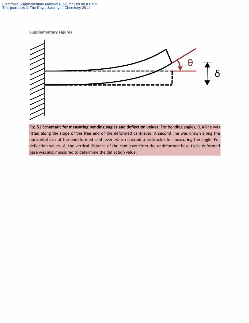
Fig. S1 Schematic for measuring bending angles and deflection values. For bending angles, θ, a line was
fitted along the slope of the free end of the deformed cantilever. A second line was drawn along the
horizontal axis of the undeformed cantilever, which created a protractor for measuring the angle. For
deflection values, δ, the vertical distance of the cantilever from the undeformed base to its deformed
base was also measured to determine the deflection value.
Electronic Supplementary Material (ESI) for Lab on a ChipThis journal is © The Royal Society of Chemistry 2011

Fig. S2 Finite element analysis of intrinsic stress on PEGDA-PC cantilevers prior to cell seeding. The
maximum displacement of (A) PEGDA-PC 700 and (B) PEGDA-PC 3400 cantilevers due to intrinsic stress
was simulated in COMSOL Multiphysics 4.2. This displacement was used to calculate intrinsic stress on
the (C) PEGDA-PC 700 and (D) PEGDA-PC 3400 cantilevers.
Electronic Supplementary Material (ESI) for Lab on a ChipThis journal is © The Royal Society of Chemistry 2011
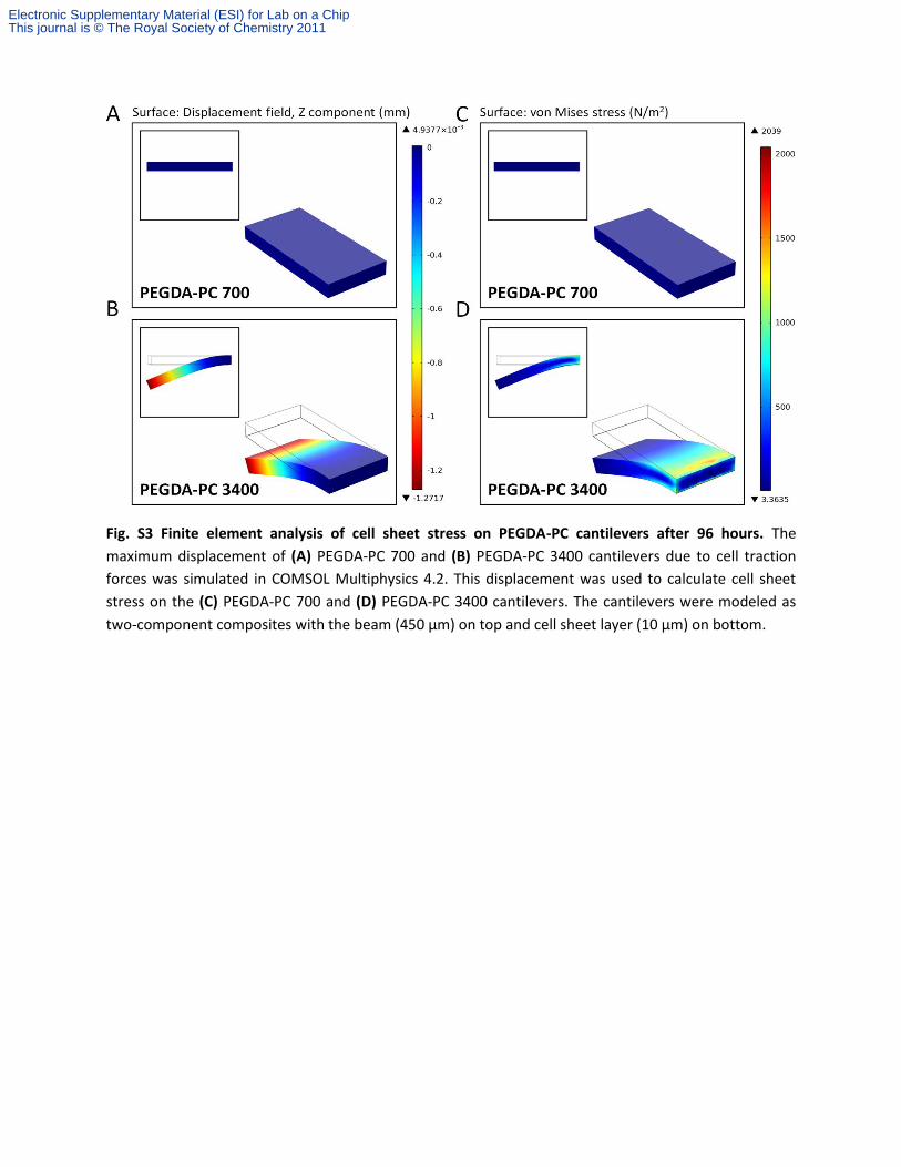
Fig. S3 Finite element analysis of cell sheet stress on PEGDA-PC cantilevers after 96 hours. The
maximum displacement of (A) PEGDA-PC 700 and (B) PEGDA-PC 3400 cantilevers due to cell traction
forces was simulated in COMSOL Multiphysics 4.2. This displacement was used to calculate cell sheet
stress on the (C) PEGDA-PC 700 and (D) PEGDA-PC 3400 cantilevers. The cantilevers were modeled as
two-component composites with the beam (450 µm) on top and cell sheet layer (10 µm) on bottom.
Electronic Supplementary Material (ESI) for Lab on a ChipThis journal is © The Royal Society of Chemistry 2011
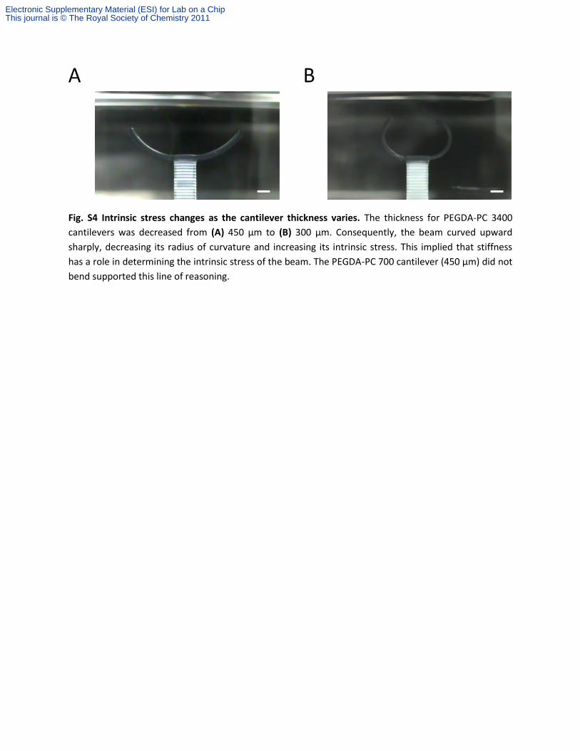
Fig. S4 Intrinsic stress changes as the cantilever thickness varies. The thickness for PEGDA-PC 3400
cantilevers was decreased from (A) 450 µm to (B) 300 µm. Consequently, the beam curved upward
sharply, decreasing its radius of curvature and increasing its intrinsic stress. This implied that stiffness
has a role in determining the intrinsic stress of the beam. The PEGDA-PC 700 cantilever (450 µm) did not
bend supported this line of reasoning.
Electronic Supplementary Material (ESI) for Lab on a ChipThis journal is © The Royal Society of Chemistry 2011
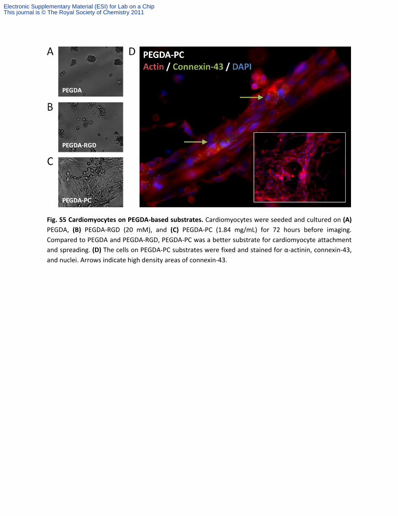
Fig. S5 Cardiomyocytes on PEGDA-based substrates. Cardiomyocytes were seeded and cultured on (A)
PEGDA, (B) PEGDA-RGD (20 mM), and (C) PEGDA-PC (1.84 mg/mL) for 72 hours before imaging.
Compared to PEGDA and PEGDA-RGD, PEGDA-PC was a better substrate for cardiomyocyte attachment
and spreading. (D) The cells on PEGDA-PC substrates were fixed and stained for α-actinin, connexin-43,
and nuclei. Arrows indicate high density areas of connexin-43.
Electronic Supplementary Material (ESI) for Lab on a ChipThis journal is © The Royal Society of Chemistry 2011

Mov. S1 Actuation of PEGDA-PC 3400 cantilevers after 72 hours of culture with cardiomyocytes.
Mov. S2 Actuation of PEGDA-PC 700 cantilevers after 72 hours of culture with cardiomyocytes.
Electronic Supplementary Material (ESI) for Lab on a ChipThis journal is © The Royal Society of Chemistry 2011