electronic wattmeter ew604 1160–00604 - bguintrlab/manuals/feedback ew604.pdfdescription 1.1...
TRANSCRIPT

ELECTRONIC
WATTMETER
EW604 1160–00604
Feedback Instruments Ltd, Park Road, Crowborough, E. Sussex, TN6 2QX, UK.
Telephone: +44 (0) 1892 653322, Fax: +44 (0) 1892 663719.
email: [email protected] website: http://www.feedback-instruments.com
Manual: EW604 Ed01-1 122013 Feedback Part No. 1160–00604

ii
Product Use
All users must familiarise themselves with the following information. This product is marked as CE compliant. This means that it complies with the relevant European Directives for this product. In particular the Directives cover Low Voltage, EMC, Machinery, Pressure and electronic waste disposal.
The equipment, when used in normal or prescribed applications and within the parameters set for its mechanical and electrical performance, should not cause any danger or hazard to health or safety.
If, in specific cases, circumstances exist in which a potential hazard may be brought about by careless or improper use, these will be pointed out and the necessary precautions emphasised.
This equipment is designed for use by students as part of the learning process who must be under the supervision of a suitably qualified and experienced person in a laboratory environment where safety precautions and good engineering practices are applied.
By the nature of its intrinsic teaching functionality, parts are visible and accessible that might normally be covered up or encased in an industrial or domestic product.
For this reason students attention should be drawn to the need to operate the equipment only in the manner prescribed in the accompanying documentation and supervisors must make students aware of any particular risk. The equipment should not be operated by any person alone.
We are required to indicate on our equipment panels certain areas and warnings that require attention by the user. These have been indicated in the specified way by yellow labels with black printing. The meanings of any labels that may be fixed to the instrument are shown below:
CAUTION - RISK OF DANGER
CAUTION - RISK OF
ELECTRIC SHOCK
CAUTION - ELECTROSTATIC
SENSITIVE DEVICE

iii
Compliance with the EMC Directive This equipment has been designed to comply with the essential requirements of the Directive. However, because of the intrinsic teaching function it cannot be electromagnetically shielded to the same extent as equipment designed for industrial or domestic use. For this reason the equipment should only be operated in a teaching laboratory environment where electromagnetic emissions in the immediate area might not be expected to cause adverse effects. In the same way users should be aware that operating the equipment near to an electromagnetic source may cause the experimental results to be outside the range expected.
The Waste Electrical and Electronic Equipment Directive (WEEE)
If this equipment is disposed of it must be in accordance with the regulations regarding the safe disposal of electronic and electrical items and not placed with ordinary domestic or industrial waste.
Product Improvements
We maintain a policy of continuous product improvement by incorporating the latest developments and components into our equipment, even up to the time of dispatch.
All major changes are incorporated into up-dated editions of our manuals and this manual was believed to be correct at the time of printing. However, some product changes which do not affect the teaching capability of the equipment, may not be included until it is necessary to incorporate other significant changes.
Component Replacement
In order to maintain compliance with the Directives all replacement components must be identical to those originally supplied.
Operating Conditions
This equipment is designed to operate under the following conditions:
Operating Temperature 10°C to 40°C (50°F to 104°F)
Humidity 10% to 90% (non-condensing)
WARNING:
This equipment must not be used in conditions of condensing humidity.

iv
Copyright Notice
© Feedback Instruments Limited
All rights reserved. No part of this publication may be reproduced, stored in a retrieval system, or transmitted, in any form or by any means, electronic, mechanical, photo-copying, recording or otherwise, without the prior permission of Feedback Instruments Limited.
ACKNOWLEDGEMENTS
Feedback Instruments Ltd acknowledge all trademarks.
MICROSOFT, WINDOWS 8, WINDOWS 7, WINDOWS VISTA, WINDOWS XP, WINDOWS 2000, WINDOWS ME, WINDOWS NT, WINDOWS 98, WINDOWS 95 and Internet Explorer are registered trademarks of Microsoft Corporation.
MATLAB is a registered trademark of Mathworks Inc. LabVIEW is a registered trademark of National Instruments.

v
Addendum This manual is for the EW604 and EW1604 Electronic Wattmeter. The EW1604 design includes a higher degree of immunity to radiated radio frequency fields in order to comply with the EMC Directive. In all other respects the specification and operating instructions for the EW604 and EW1604 are the same. The only other difference is that the protective fuse in the input lines (not the mains fuse) has been moved from the rear to the front panel.

vi
Electronic Wattmeter
CONTENTS
CHAPTER 1 Description 1.1 Introduction 1.2 Mechanical 1.3 Electrical specification
CHAPTER 2 Operation 2.1 Installation of EW604 2.2 Power supply voltage selection 2.3 Wire connections 2.4 Range selection 2.5 Connection of EW604 to circuit under test 2.6 Measuring power in a three-phase system 2.7 Measuring systems with low power factor 2.8 Amplifier power measurement 2.9 Measuring power in audio frequency circuits 2.10 Audio frequency power comparison 2.11 Measuring radio frequency power
CHAPTER 3 Circuit Description 3.1 Multiplying circuit 3.2 Overload circuits 3.3 Power supply circuit
CHAPTER 4 Maintenance 4.1 Access 4.2 Alignment schedule 4.3 Component replacement table
3
METER AMPS~ O/~ ·S '
C POWER ;q REV .j
Hi
SET ZERO
FEEDBACK ELECTRONIC WATTMETER EWS04
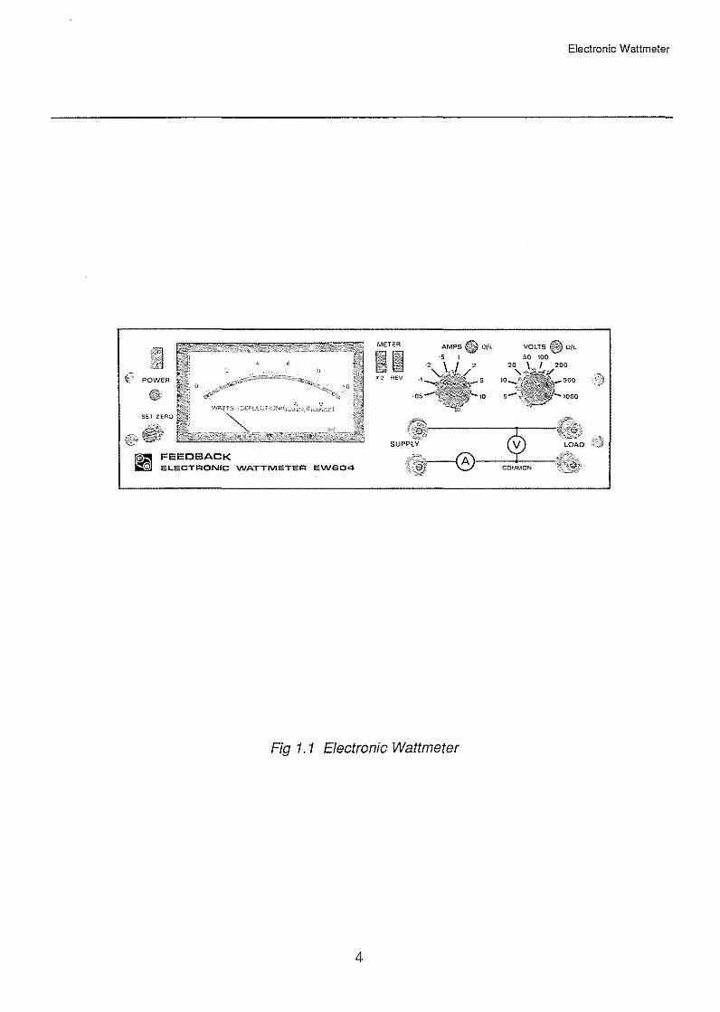
Fig 1. 1 Electronic Wattmeter
4
Electronic Wattmeter
VOLTS. 0/L
so 100

DESCRIPTION
1.1 Introduction
Electronic Wattmeter
CHAPTER 1
The Feedback EW604 Electronic Wattmeter is based on an analogue multiplying circuit using the logarithmic voltage-tocurrent transistor characteristic. The inputs to this multiplying circuit are currents that are derived via range-scaling resistors from the input voltage terminals and the input current terminals. The output is displayed on the front panel moving-coil meter calibrated in watts.
The wattmeter terminals are arranged as two pairs marked 'SUPPLY' and 'LOAD' to facilitate correct connection.
Separate warning lights are provided on the voltage input and current input to indicate when an overload might affect the reading accuracy. Additional precautions are taken to prevent damage to the instrument in the event of gross overload of current or voltage.
Pushbuttons enable the meter deflection to be reversed to measure reverse power flows and also to increase the meter sensitivity by x2 to improve readability of small deflections.
The wattmeter contains its own partly-regulated power supply for operation on normal line voltages.
The value of the wattage is displayed on the front panel meter which responds to the true wattage or potential heating ability of the current in the associated load. In a resistive load this corresponds to:
2 2 (V rmsl . .
(I rmsl R or R 1rrespect1ve of waveform*
and to: (Irmsl (Vrmsl cos <jl, in a reactive circuit with sinusoidal excitation and in general to:
T
Limit T1 J v i dt
T->= 0
*High crest values applied to EW604 will illuminate the 0/L lamp(s) if they are of such a value as to cause limiting in the circuit and thus errors.
5
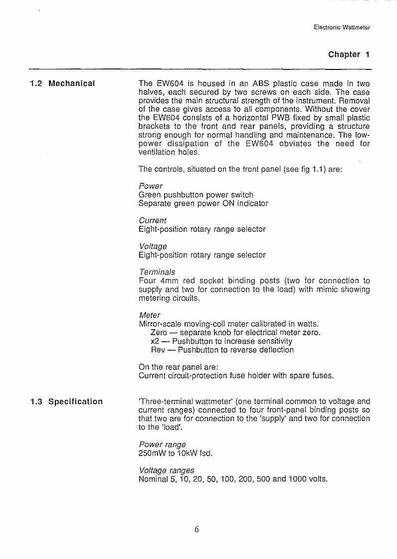
1.2 Mechanical
1.3 Specification
Electronic Wattmeter
Chapter 1
The EW604 is housed in an ABS plastic case made in two halves, each secured by two screws on each side. The case provides the main structural strength of the instrument. Removal of the case gives access to all components. Without the cover the EW604 consists of a horizontal PWB fixed by small plastic brackets to the front and rear panels, providing a structure strong enough for normal handling and maintenance. The lowpower dissipation of the EW604 obviates the need for ventilation holes.
The controls, situated on the front panel (see fig 1.1) are:
Power Green pushbutton power switch Separate green power ON indicator
Current Eight-position rotary range selector
Voltage Eight-position rotary range selector
Terminals Four 4mm red socket binding posts (two for connection to supply and two for connection to the load) with mimic showing metering circuits.
Meter Mirror-scale moving-coil meter calibrated in watts.
Zero- separate knob for electrical meter zero. x2- Pushbutton to increase sensitivity Rev - Pushbutton to reverse deflection
On the rear panel are: Current circuit-protection fuse holder with spare fuses.
'Three-terminal wattmeter' (one terminal common to voltage and current ranges) connected to four front-panel binding posts so that two are for connection to the 'supply' and two for connection to the 'load'.
Power range 250mW to 1 OkW fsd.
Voltage ranges Nominal 5, 10, 20, 50, 100, 200, 500 and 1000 volts.
6
Burden
Meter
Accuracy
Scale Accuracy
Electronic Wattmeter
Chapter 1
No more than 1.5kV peak should be applied between the upper pair of terminals and either ground or the lower terminals. The latter must not exceed 400V peak to ground.
Current ranges Nominal 0.05, 0.1, 0.2, 0.5, 1, 2, 5 and 1 OA.
Overload Indication Input peaks of voltage or current in excess of 1.5x the nominal range can cause overload which is clearly indicated by the appropriate voltage or current overload lamp.
Overload Protection All current circuits are protected by a 1 OA slow-blow 1/4" x 1 1/4" fuse mounted on the rear panel. The circuit is designed to withstand the transient associated with normal rupturing of this fuse on all current ranges. The voltage circuit will withstand the nominal 250V a.c supply indefinitely on any range.
Frequency range DC to 20kHz.
All voltage ranges; 5kQ/Volt All current ranges; less than 60mQ
3 1 /4" mirror scale graduated 0 to 1.0 in 50 divisions Reading given by: Watts= (meter deflection) x (Voltage range) x (Current range) Pushbutton to give x2 scale expansion and pushbutton meter reversal.
Many factors control the final indication on any wattmeter. They include voltage, current and power ranges, power factor, temperature and frequency.
The possible permutations of these are so numerous that it is impracticable to specify or to test instruments under all likely operating conditions. The figures below should be interpreted in the light of these comments.
All figures are at 50Hz, unity power factor, 25oc.
Typically better than 1.5% of fsd measured on 1 OOV and 0.5A range at 20, 40, 60, 80 and 100% of fsd with a 200 ohm load (guaranteed better than 2.5% of fsd).
Also typically better than 2% of fsd for all combinations of 0.25A, 0.5V, 0. 75A and 1 A with 25V, 50V, 75V and 1 OOV applied to the 1 A and 1 OOV ranges.
7

Range-to-range Accuracy
Reference Point Power
10kW
1kW
~
Q)
~ 100W 0..
DC
Carrying Handle
Power Requirements
Fuse
Electronic Wattmeter
Chapter 1
Errors in the current and voltage range multipliers contribute a combined error to power indication that is typically less than 1% of reading (guaranteed less than 2.3% of reading).
This is at full-scale on the 1 OOV and 0.5A range and is set to within 0.3% of 50W.
Note 1) In general, scale errors are not affected by choice of range.
2) Typical figures are determined from measurements made on a single batch of instruments.
3) Guaranteed figures are from measurements made on every instrument.
Fig 1.2 shows the area of operation within which the EW604 may be expected to give results accurate to better than ±5% of fsd and should be interpreted in conjunction with the accuracy figures given for the calibration frequency of 50Hz.
Area of operation
10 50 100 1k 10k 20k Calibration Frequency Frequency Hz----e.
Fig 1.2
A dual purpose handle is fitted for use in carrying the instrument or serving as a stable stand to present the instrument panel at a convenient working angle.
Line voltage 200/250V or 1 00/125V rms 50 or 60Hz
Consumption 4 V.A.
315mA slow blow (200mm x 5mm) Littelfuse style 213 Beswick TTC123, Buss GMA
8
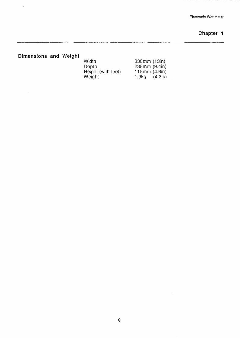
Dimensions and Weight Width Depth Height (with feet) Weight
9
330mm (13in) 238mm (9.4in) 118mm (4.6in) 1.9kg (4.31b)
Electronic Wattmeter
Chapter 1

Electronic Wattmeter
NOTES
10

OPERATION
2.1 Installation of EW604
2.2 Power Supply Voltage Selection
2.3 Wire Connections
2.4 Range Selection
Electronic Wattmeter
CHAPTER 2
Inspect the EW604 and if any damage is evident, immediately notify the carriers and your supplier.
Ensure that the instrument is set to the appropriate voltage supply either by inspecting the tag (if fitted) on the power cable or by removing the top cover of the instrument. See Chapter 4.1.
Before removing the covers, however, ensure that the mains plug is disconnected.
The voltage selection is accomplished by a slide switch on the printed circuit board. Set the switch to '115' for operation from 100 to 125V and to '230' for 200 to 250V, 50/60Hz AC.
The colour code of the power supply cable is:
Brown Blue Green/Yellow
Live Neutral Ground
The ground wire is connected to the graphite screening of the case but is isolated from the front panel 'common' terminal.
The current and voltage ranges should be selected to suit the current voltage present in the circuit under test. This is conveniently done by progessively increasing the sensitivity by means of the appropriate range switch until the corresponding overload indicator lights, and then switching back one range. This should be done with both the current ranges and voltage ranges.
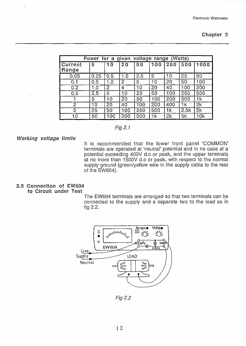
The table in fig 2.1 lists the full-scale power for the various current and voltage range combinations.
1 1
Electronic Wattmeter
Chapter 2
Power for a given voltage range (Watts) Current Range
0.05 0.1 0.2 0.5 1 2 5 10
Working voltage limits
2.5 Connection of EW604 to Circuit under Test
5 10 20 50 100 200 500 1000
0.25 0.5 1.0 2.5 5 10 25 50 0.5 1.0 2 5 10 20 50 100 1.0 2 4 10 20 40 100 200 2.5 5 10 25 50 100 250 500 5 10 20 50 100 200 500 1k 10 20 40 100 200 400 1k 2k 25 50 100 250 500 1k 2.5k 5k 50 100 200 500 1k 2k 5k 10k
Fig 2.1
It is recommended that the lower front panel 'COMMON' terminals are operated at 'neutral' potential and in no case at a potential exceeding 400V d.c or peak, and the upper terminals at no more than 1500V d.c or peak, with respect to the normal supply ground (green/yellow wire in the supply cable to the rear of the EW604).
The EW604 terminals are arranged so that two terminals can be connected to the supply and a separate two to the load as in fig 2.2.
Live Supply
Neutral
Fig 2.2
1 2

Supply
Electronic Wattmeter
Chapter 2
The current-sensing circuit is in the lower line and should be connected in the neutral line. (This is good practice since it keeps low the operating potential of the wattmeter common connection). However, if necessary, it is possible to operate with the upper line at neutral. (This situation may occur where it is not possible to break the neutral line or where a dangerous situation would be created if the 1 OA overload protective fuse in series with the current-sensing circuit were ruptured). The live voltage must not then exceed 280V with respect to ground.
With conventional dynamometer wattmeters a decision has to be made before connection whether to include the internally consumed watts of the current coils or the voltage coils in the power supply measured.
With the EW604 connected as in fig 2.3(a) the power consumed by the voltage circuit at (5000 ohms/V) is so small that it is insignificant compared with load power. This enables the prearranged connections as shown on the front panel schematic to be used without need for correction.
However the EW604 may, if desired, be connected as in fig 2.3(b). This introduces a small voltage drop (about 60mV/A) in the current sensing circuit. The reading can be corrected if necessary by subtracting the I2R loss from the EW604 reading.
Wattmeter '" ___________ ,
Figs 2.3(a)
Load WL
Wattmeter ... -----------,
I ' , __., l-r'----,
Warning
' ' ' --- --------
Fig 2.3(b)
Load WL
As with an electrical measuring instrument care must be taken to avoid contact with supply voltages associated with the test circuit. Switch off the supply voltage before making connections to the wattmeter terminals and avoid contact with these terminals during the test.
1 3

Electronic Wattmeter
Chapter 2
2.6 Measuring Power in a Three-phase System
Balanced system
Polyphase measurements invariably require connection of the common terminal of the EW604 to at least one live line. The line voltage must then not exceed 280V. For three-phase systems this implies a maximum line voltage of 490V.
If both the supply and the load are balanced and either a neutral is available on the supply or a star point on the load, the power can be measured by connecting as in fig 2.4 and multiplying the reading obtained by three.
EW604
3 phase supply{----.:8::.._
y ~~-L~-.
a) Supply neutral available
3 phase JRB supply ty
b) Star point of load available
Fig 2.4 Finding the power in a balanced load system
If the supply and load are balanced, both the power and the power factor can be obtained from two readings using the connections of fig 2.5. Two readings P1 and P2 are taken using the two positions of the switch. The power is then given by P1 + P2, and the power factor is
1 2
p1 1--
1 + 3 p2
p1 1+-
p2
14
Electronic Wattmeter
Chapter 2
3 phase {~~'--~t_..--1 Balanced supply 8 Load
:-"---L_.::.:::.:::..:::___J
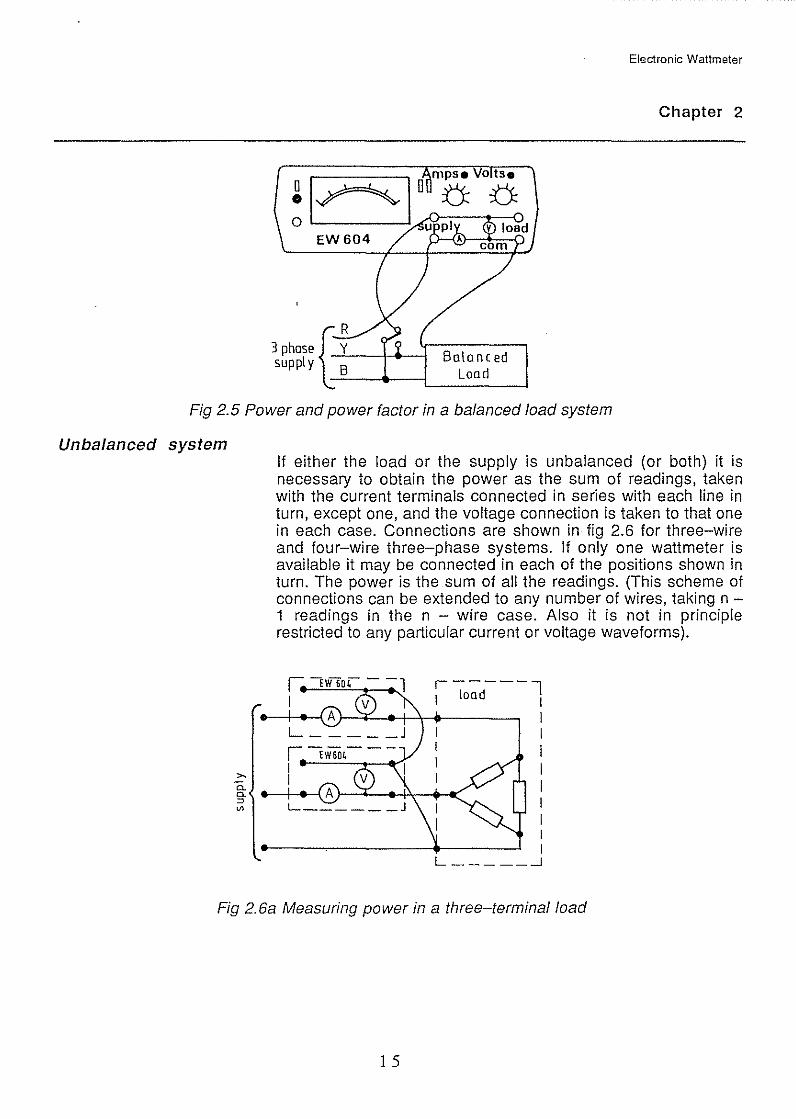
Fig 2.5 Power and power factor in a balanced load system
Unbalanced system If either the load or the supply is unbalanced (or both) it is necessary to obtain the power as the sum of readings, taken with the current terminals connected in series with each line in turn, except one, and the voltage connection is taken to that one in each case. Connections are shown in fig 2.6 for three-wire and four-wire three-phase systems. If only one wattmeter is available it may be connected in each of the positions shown in turn. The power is the sum of all the readings. (This scheme of connections can be extended to any number of wires, taking n -1 readings in the n - wire case. Also it is not in principle restricted to any particular current or voltage waveforms).
,-----l 1 load
1 I I I I I I I I I L _____ _j
Fig 2.6a Measuring power in a three-terminal load
1 5

Electronic Wattmeter
Chapter 2
N
Fig 2.6b Measuring power in an unbalanced star-connected load
2.7 Measuring Systems with Low Power Factor
It is possible with conditions of low power factor or high crest factor that only a small deflection is obtainable without overloading. This is a direct result of the real power being low in the circuit and thus it is unreasonable to expect a large deflection. In practice low power factors are commonly encountered when measuring, for example, the iron loss of transformers. In this case the magnetising current may cause overloading of the wattmeter when it is displaying a very small deflection corresponding to a small iron loss. This difficulty may be overcome by the use of power factor correction capacitors. In theory the use of such capacitors to 'tune' the transformer inductance does not affect the power reading but it does reduce the supply current enabling a more sensitive current range to be used without overloading the wattmeter, thereby providing a more significant deflection.
The capacitor used as shown in fig 2.7 can be, for convenience, a decade box of suitable voltage rating and value. The loss angle of most commercial capacitor boxes is so small that it is insignificant compared with normal power transformer loss angles and so requires no correction.
The value of the capacitors is not critical, it being adjusted on test to extinguish the current overload indication.
1 6
I Decade Capacitor
From supply Neutral
Box
Electronic Wattmeter
c c I .
Chapter 2
Trans former Under Test
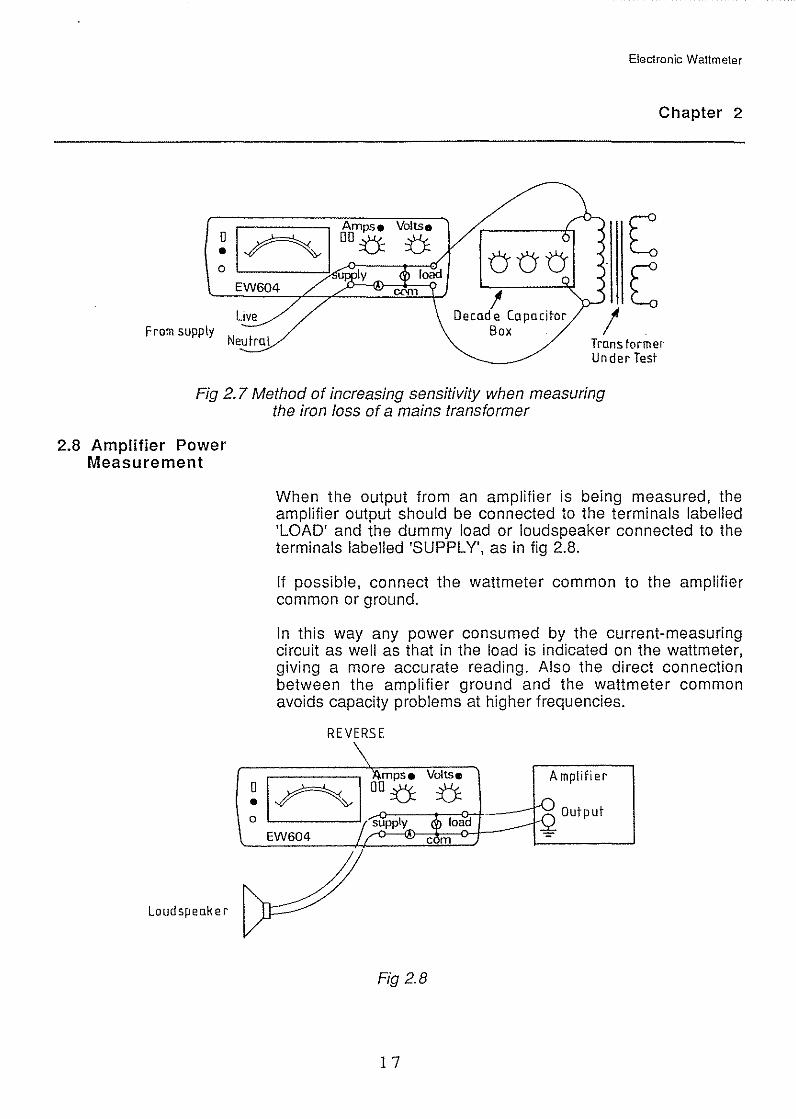
Fig 2. 7 Method of increasing sensitivity when measuring the iron loss of a mains transformer
2.8 Amplifier Power Measurement
Loudspeaker
0 • 0
When the output from an amplifier is being measured, the amplifier output should be connected to the terminals labelled 'LOAD' and the dummy load or loudspeaker connected to the terminals labelled 'SUPPLY', as in fig 2.8.
If possible, connect the wattmeter common to the amplifier common or ground.
In this way any power consumed by the current-measuring circuit as well as that in the load is indicated on the wattmeter, giving a more accurate reading. Also the direct connection between the amplifier ground and the. wattmeter common avoids capacity problems at higher frequencies.
REVERSE
mpse Voltse DO ::{J: jj:_
Amplifier
EW604
Fig 2.8
1 7

2.9 Measuring Power in
Electronic Wattmeter
Chapter 2
Although the previous circuit is the preferred connection the error associated with a more normal connection is comparatively small.
For example with a 3-ohm loudspeaker or load the expected error due to normal connection of the current measuring circuit of 60mQ is:
6~~Q X 1 00%= 2%
This is probably low compared with errors introduced by normal load or loudspeaker connection cables.
For higher impedance loads the error is even smaller.
Audio Frequency Circuits
Power outputs associated with audio amplifiers are often quoted as 'Watts rms'. If it is assumed that 'Watts rms' has the same meaning in relation to watts as volts rms does to volts, then 'Watts rms' means:
the 'Square root of the mean value of the square of the instantaneous watts'.
It is by no means certain that this is always intended when 'watts rms' is used.
It may sometimes be employed to denote 'real' power as opposed to 'reactive' or 'imaginary' power but, as such, is a misnomer.
It may be noted that in the strict sense Watts rms does not correspond to any useful physical reality and its relationship to normal Watts is dependent on the waveform.
The table in fig 2.9 shows various basic voltage waveforms all drawn to the same scale for the 1 volt rms and hence for 1 watt in 1 ohm together with the associated values of Volts peak and Watts rms.
1 8

Voltage Vrms :. Watts Vpk Waveform in 1Q load
IV (0(1 1 1 1 OV
',:rn= 1 1 1
::y:~ 1 1 1.414
-J2
IVA-····f·· 1 1 1.732
..J3 ov v
1 1 1.414
~V·-n--··r- 1 -J2
Fig 2.9 Table showing basic voltage waveforms
2.10 Audio Frequency Power Comparison
Electronic Wattmeter
Chapter 2
Wrms
1
1
1.225
if 1.342
if 1.414
-J2
In the audio range of frequencies, power measurement comparisons between two systems having values P1 and P2 can be expressed logarithmically in terms of the decibel (dB). being one tenth of a bel.
The expression then is:
p2 dB= 10 log -
10 p1
The standard reference unit for P1 is 1 milliwatt of power in a 600-ohm resistive load.
I 9
2.11 Measuring Radio Frequency Power
Variable transformer
0
Electronic Wattmeter
Chapter 2
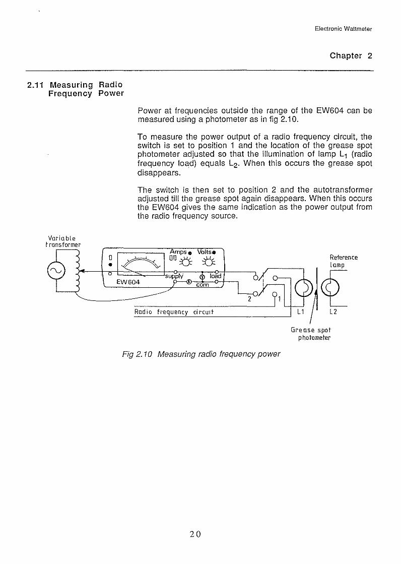
Power at frequencies outside the range of the EW604 can be measured using a photometer as in fig 2.1 0.
To measure the power output of a radio frequency circuit, the switch is set to position 1 and the location of the grease spot photometer adjusted so that the illumination of lamp L1 (radio frequency load) equals L2 . When this occurs the grease spot disappears.
The switch is then set to position 2 and the autotransformer adjusted till the grease spot again disappears. When this occurs the EW604 gives the same indication as the power output from the radio frequency source.
Amps • Voltse 00 ::():: u
supply
Reference lamp
EW604 ~ Radio frequency circUit
Fig 2. 10 Measuring radio frequency power
20
l2
Grease spot photometer

CIRCUIT DESCRIPTION
Current
,-------~C
Difference Circuit
A B
Electronic Wattmeter
CHAPTER 3
input o---r-~:::::J~----<1
Shunt Resistor
3.1 Multiplying Circuit
Voltage
~----~====~~====~~i~nput
~ 21
Fig 3.1
~ 2[ Series Resistor
The EW604 is designed around a four-quadrant analogue multiplier circuit which makes use of the logarithmic relationship between the emitter base voltage and the emitter current of a transistor, to effect the multiplication process.
The circuit is designed to accept current inputs directly so that interfacing with the wattmeter input terminals needs only a series resistor for the voltage input and a pair of current-dividing resistors for the current input.
The basic multiplying circuit is shown in fig 3.1 while the full circuit is shown in the Maintenance Chapter as fig 4.3.
Transistors TR1 to TR5 are a matched array. All the emitters are at virtual earth points and all the base currents are supplied by operational amplifiers AC or AA.
The output product is the difference between collector currents at A and B.
These points are again held at 'virtual earths' at about +0.7V by operational amplifiers in the difference circuit (AD and AE in fig 4.3) which are connected to provide an output voltage at C (fig 3.1) proportional to the difference in current of A and B. The gain of the difference circuit (mutual resistance) is adjusted by a potentiometer (R42 in fig 4.3). Another operational amplifier (AF in fig 4.3) is connected as a voltage follower to drive the moving coil meter.
2 1
3.2 Overload Circuits
3.3 Power Supply Circuit
Electronic Wattmeter
Chapter 3
A considerable proportion of the EW604 circuitry is concerned with coping with overload. The overload condition is catered for in two ways on both the current and the voltage inputs, firstly by indicating when an input exceeds the linear input range and secondly by protection against damage for larger inputs.
In the main circuit of fig 4.3 the current input, TR9 and TR1 0 detect overload conditions at the output of AC and AA switching on TR11 thereby illuminating the overload indicator. The current circuit is protected against excessive inputs by the 1 OA slowblow fuse. Diodes 01 and 02 protect the input of AC from excessive voltages until the fuse ruptures.
With the voltage input, TR6 and TR7 detect voltage excursions outside the linear range and illuminate the overload indicator via TR8. Excessive input voltages cause the emitter base junction of TR6 to conduct, the current being limited by R2, R3, R4 and R5 and the switched voltage range resistor, these components being of sufficient wattage rating to withstand the normal mains supply voltage indefinitely.
The power supply provides from a single rectified and smoothed output:
-7.5V zener regulated, +0.7V and +24V unregulated.
22
MAINTENANCE
4.1 Access
Electronic Wattmeter
CHAPTER 4
WARNING
Before working on the instrument with the case removed the following precautions must be observed.
Disconnect all external connections to the instrument be"fore removing the case.
After removing the case, check care-tully to see whether any conductors or terminals in the mains circuit are exposed. Points to check include the entry of the power supply cable, the fuse, the power switch, the voltage adjusting switch and the main connections to the power transformer.
EVERY PART OF THE MAINS CIRCUIT CAN CARRY DANGEROUS VOLTAGE. WHILE THE POWER CABLE IS CONNECTED, AVOID ALL CONTACT.
The wattmeter has been designed to allow access to all the components by removal of the case.
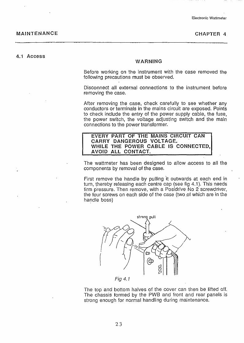
First remove the handle by pulling ·it outwards at each end in turn, thereby releasing each centre cap (see fig 4.1 ). This needs firm pressure. Then remove, with a Posidrive No 2 screwdriver, the four screws on each side of the case (two .of which are in the handle boss)
Fig 4.1
The top and bottom halves of the cover can then be lifted off. The chassis formed by the PWB and front and rear panels is strong enough for normal handling during maintenance.
23
Electronic Wattmeter
Chapter 4
On replacing the handle, press home the centre caps and then rotate them until they click into position.
The handle also acts as a stand and can be re-positioned by easing outwards the two ends simultaneously.
Positions of components and test points referred to in the following text can be found by reference to the component layout, fig 4.2 and the complete circuit diagram fig 4.3.
Faults will show by inaccurate readings or by no sensible reading at all.
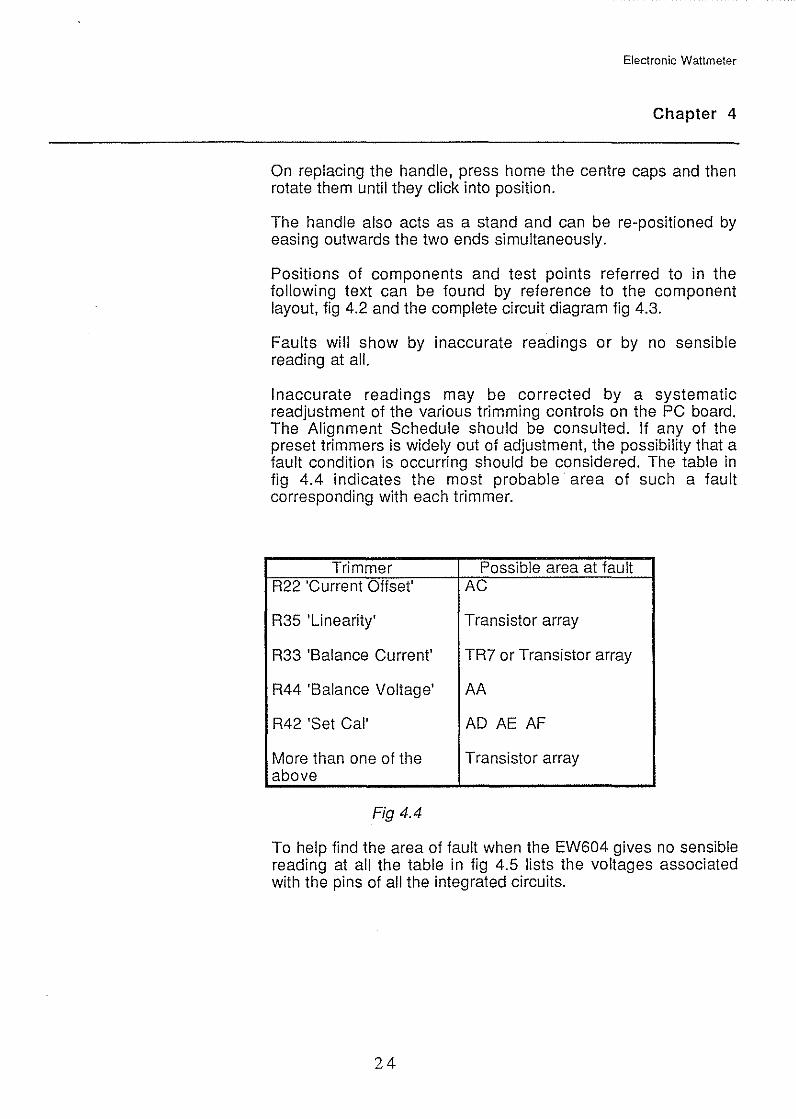
Inaccurate readings may be corrected by a systematic readjustment of the various trimming controls on the PC board. The Alignment Schedule should be consulted. If any of the preset trimmers is widely out of adjustment, the possibility that a fault condition is occurring should be considered. The table in fig 4.4 indicates the most probable· area of such a fault corresponding with each trimmer.
Trimmer Possible area at fault R22 'Current Offset' AC
R35 'Linearity' Transistor array
R33 'Balance Current' TR? or Transistor array
R44 'Balance Voltage' AA
R42 'Set Cal' AD AE AF
More than one of the Transistor array above
Fig 4.4
To help find the area of fault when the EW604 gives no sensible reading at all the table in fig 4.5 lists the voltages associated with the pins of all the integrated circuits.
24
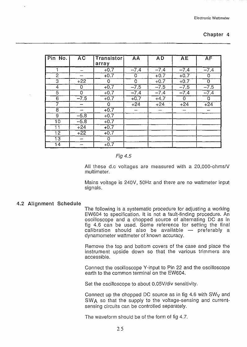
Pin No.
1 2 3 4 5 6 7 8 9 10 1 1 12 13 14
Electronic Wattmeter
Chapter 4
AC Transistor AA AD AE AF array
- +0.7 -7.4 -7.4 -7.4 -7.4 - +0.7 0 +0.7 +0.7 0
+22 0 0 +0.7 +0.7 0 0 +0.7 -7.5 -7.5 -7.5 -7.5 0 +0.7 -7.4 -7.4 -7.4 -7.4
-7.5 +0.7 +0.7 +4.7 0 0 - 0 +24 +24 +24 +24 - +0.7 - - - -
-5.8 +0.7 -5.8 +0.7 +24 +0.7 +22 +0.7 - 0 - +0.7
Fig 4.5
All these d.c voltages are measured with a 20,000-ohms/V multi meter.
Mains voltage is 240V, 50Hz and there are no wattmeter input signals.
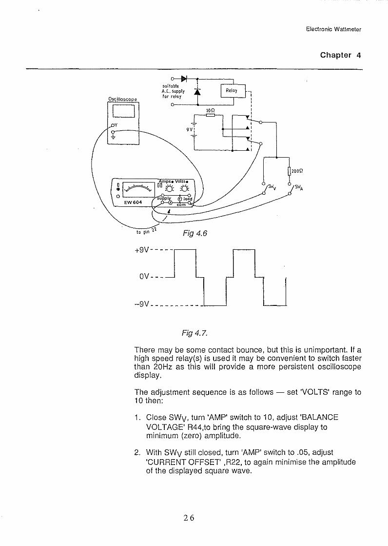
4.2 Alignment Schedule The following is a systematic procedure for adjusting a working EW604 to specification. It is not a fault-finding procedure. An oscilloscope and a chopped source of alternating DC as in fig 4.6 can be used. Some reference for setting the final calibration should also be available - preferably a dynamometer wattmeter of known accuracy.
Remove the top and bottom covers of the case and place the instrument upside down so that the various trimmers are accessible.
Connect the oscilloscope Y-input to Pin 22 and the oscilloscope earth to the common terminal on the EW604.
Set the oscilloscope to about 0.05V/div sensitivity.
Connect up the chopped DC source as in fig 4.6 with SWv and SWA so that the supply to the voltage-sensing and currentsensing circuits can be controlled separately.
The waveform should be of the form of fig 4. 7.
25
Oscilloscope
D
!>uilob!e -, A .C. !>Upp!y
for reloy '---.---' : o---~~----_j '
1011
Fig 4.6
+9V--- --
OV--- - '- '
-9V--- --------
Fig 4.7.
Electronic Wattmeter
Chapter 4
20011
'-
There may be some contact bounce, but this is unimportant. If a high speed relay(s) is used it may be convenient to switch faster than 20Hz as this will provide a more persistent oscilloscope display.
The adjustment sequence is as follows - set 'VOLTS' range to 10 then:
1. Close SWv, turn 'AMP' switch to 1 0, adjust 'BALANCE VOLTAGE' R44,to bring the square-wave display to minimum (zero) amplitude.
2. With SWv still closed, turn 'AMP' switch to .05, adjust 'CURRENT OFFSET' ,R22, to again minimise the amplitude of the displayed square wave.
26
-
-Before
adjurment
After
to
- - r-
Electronic Wattmeter
Chapter 4
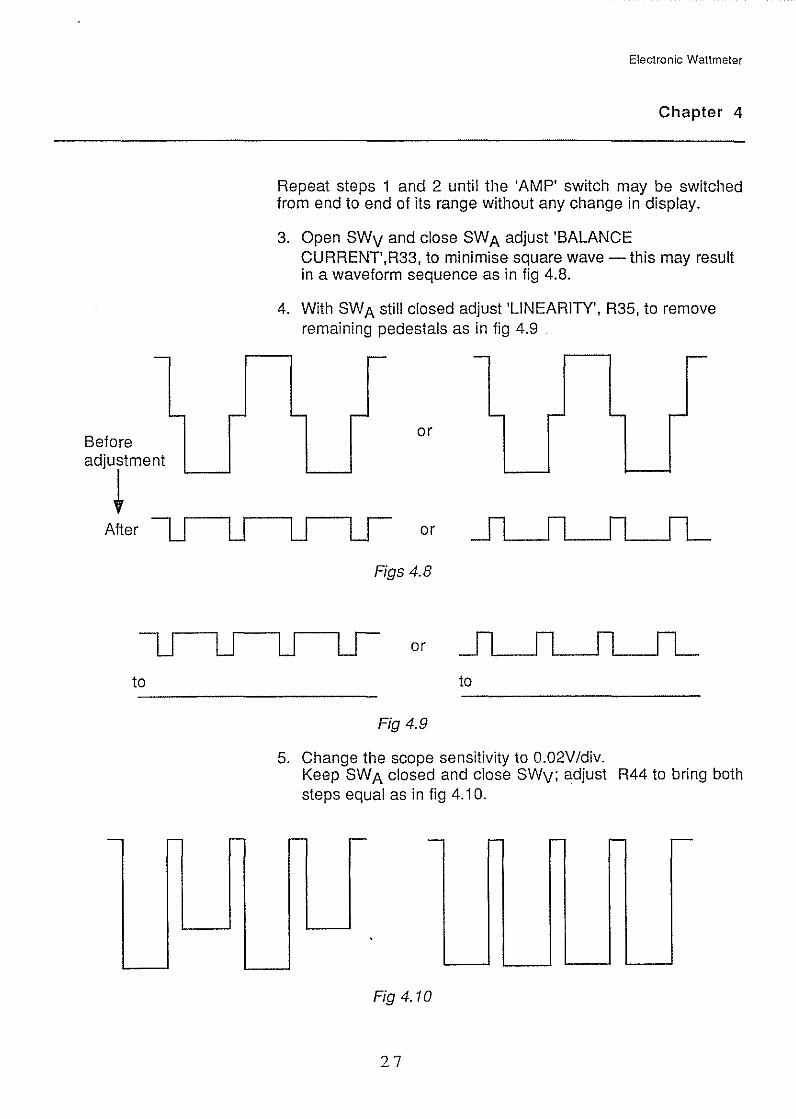
Repeat steps i and 2 until the 'AMP' switch may be switched from end to end of its range without any change in display.
3. Open SWv and close SW A adjust 'BALANCE CURRENT',R33, to minimise square wave -this may result in a waveform sequence as in fig 4.8.
4. With SW A still closed adjust 'LINEARITY', R35, to remove remaining pedestals as in fig 4.9
- -
- - - r-or
or
Figs 4.8
or
to
Fig 4.9
5. Change the scope sensitivity to 0.02V/div. Keep SWA closed and close SWv; adjust R44 to bring both steps equal as in fig 4. i 0.
r- r- - r- - - ;--
Fig4.10
27
Electronic Wattmeter
Chapter 4
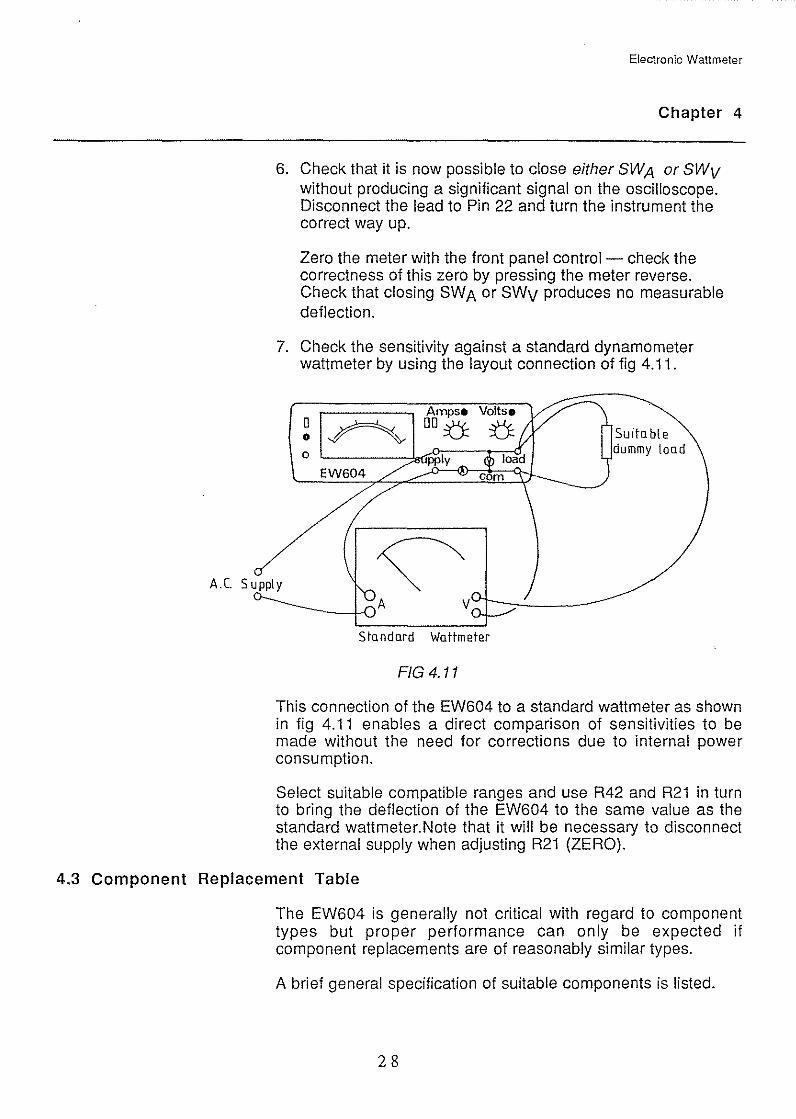
6. Check that it is now possible to close either SWA or SWv without producing a significant signal on the oscilloscope. Disconnect the lead to Pin 22 and turn the instrument the correct way up.
Zero the meter with the front panel control- check the correctness of this zero by pressing the meter reverse. Check that closing SWA or SWv produces no measurable deflection.
7. Check the sensitivity against a standard dynamometer wattmeter by using the layout connection of fig 4.11.
A.C. Supply
Standard Wattmeter
FIG 4.11
Su1table dummy load
This connection of the EW604 to a standard wattmeter as shown in fig 4.11 enables a direct comparison of sensitivities to be made without the need for corrections due to internal power consumption.
Select suitable compatible ranges and use R42 and R21 in turn to bring the deflection of the EW604 to the same value as the standard wattmeter.Note that it will be necessary to disconnect the external supply when adjusting R21 (ZERO).
4.3 Component Replacement Table
The EW604 is generally not critical with regard to component types but proper performance can only be expected if component replacements are of reasonably similar types.
A brief general specification of suitable components is listed.
28
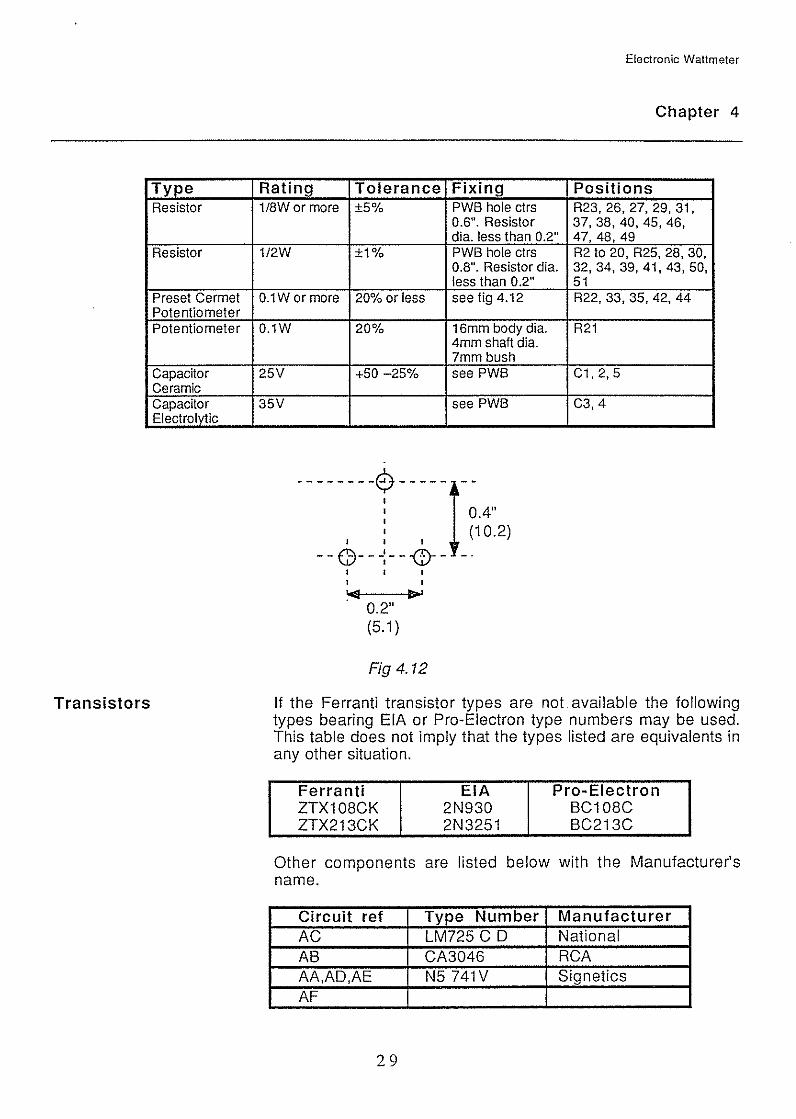
Type Resistor
Resistor
Preset Cermet Potentiometer Potentiometer
Capacitor Ceramic Capacitor Electrolytic
Transistors
Electronic Wattmeter
Chapter 4
Rating Tolerance Fixing Positions 1/8W or more ±5% PWB hole ctrs R23, 26, 27, 29, 31,
0.6". Resistor 37, 38, 40, 45, 46, dia. less than 0.2" 47,48,49
1/2W ±1% PWB hole ctrs R2 to 20, R25, 28, 30, 0.8". Resistor dia. 32,34, 39,41, 43,50, less than 0 .2" 51
0.1W or more 20% or less see fig 4.12 R22,33,35,42,44
0.1W 20% 16mm body dia. R21 4mm shaft dia. 7mm bush
25V +50 -25% see PWB C1, 2, 5
35V see PWB C3, 4
------ --r -----1- ;16·:2) I I I
--C)---:-- -G)-- -. I I I I I
1014 II> I
. 0.2" (5.1)
Fig 4.12
If the Ferranti transistor types are not. available the following types bearing EIA or Pro-Electron type numbers may be used. This table does not imply that the types listed are equivalents in any other situation.
Ferranti EIA Pro-Electron ZTX108CK 2N930 BC108C ZTX213CK 2N3251 BC213C
Other components are listed below with the Manufacturer's name.
Circuit ref Type Number Manufacturer AC LM725 CD National AB CA3046 RCA AA,AD,AE N5 741V Signetics AF
29
Returned Instruments
Electronic Wattmeter
Chapter 4
Other components including the mains transformer, R1, the meter, and the switches are supplied to Feedback specifications and should be ordered through Feedback Instruments Ltd, Crowborough, Sussex.
Should the instrument be returned for repair and recalibration at any time, the mains plug should be removed, as no provision for the plug is included in the packing when we return the instrument to you. The address to which an instrument should be returned is:
Feedback Instruments Limited Servicing Department Park Road Crowborough, TN6 2QR Sussex, England.
30

w -
~ ;4 1\)
() a .g a :::, (J) :::, ~
r--
~ c: ~
B <i3 ~ ~
I Ol a .!;.
~ Ol
~ (jj (/)
.::::
,.. pg PT flO li;I 2511-129
•CJ 1l Jll t.Kl -:00- rli f1l ~ R7 05 ~ 6 I R37 AB • I I ,
CJ I R~ 1 .. 1 1 .. 1
R32 R33 R28 sz LKI e ~ t.K:J U')ao TRs ~ R3sG R3B u 1
" R45 ~ITR90 I 0~~ 51 ~ QR22 -DLJ- R<as r rL~o " AA -[]!]- R40 I I
-GD- 0 cs as n··D R29
81 e TR11
0 TRB r::-l_ i1 R46s R41 ~ /
35 R2 RJ R4 RS R44~AC ir.Ji 3
~ ~ ~ ~ C2 "17 ~' [] '
" 51 51 51 " + D1 -Ji24 ~ 0 0 R31s ,-1, R23 1,.1
"
~~~~M~
C1 e ~R13 .. l1
0 0"
R47 -[]!]-
0 12
--71
+
"0
T1 I 1•..=5 11
"'
~. 010
. 011
. ··-Im-C3 21
1 R49- 06 -fJI:J-, . -1iLF
AD~ " R27 . FEEDBACK ·-oo
R30 -j " fAE f1l
PWB
1-604-B2GOA~ ISS 5
El R34
-1 " f-R39 -f I! f- R42 AF ~- f~~
LK7-f fl ....
I R43
~ 2
•
,. zs 2S 21 " " 0 DO 0 0 0
31
0
" 0
FS2
31SrnA
11
0 " 0
R51~ ORSO 9!: 9,; Q 9 9 \?n6W3 SW4 U 45 0 0 " .
DDDDDDDD 12345618 B260C-S swsn· 21
m iii n.
0 a :::; :>
Ill c;·
-o :::: - " CD §' .... ro .1> ~

Electronic Wattmeter
Chapter 4
~ ,~----------~~----------J
Fig 4.3 Circuit Diagram (Drg No. 2-604-8269 Iss 5)
32