031c074.netsolhost.com031c074.netsolhost.com/.../2014/09/9m-mro-aes-antenna-techspecs.pdfconformal...
TRANSCRIPT
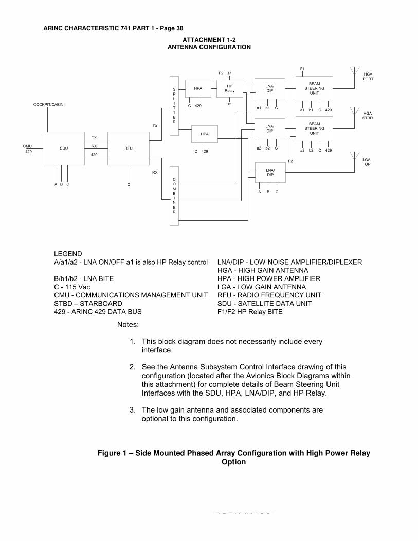
ARINC CHARACTERISTIC 741 PART 1 - Page 38
ATTACHMENT 1-2 ANTENNA CONFIGURATION
LEGEND
A/a1/a2 - LNA ON/OFF a1 is also HP Relay control LNA/DIP - LOW NOISE AMPLIFIER/DIPLEXER
HGA - HIGH GAIN ANTENNA
B/b1/b2 - LNA BITE HPA - HIGH POWER AMPLIFIER
C - 115 Vac LGA - LOW GAIN ANTENNA
CMU - COMMUNICATIONS MANAGEMENT UNIT RFU - RADIO FREQUENCY UNIT
STBD – STARBOARD SDU - SATELLITE DATA UNIT
429 - ARINC 429 DATA BUS F1/F2 HP Relay BITE
Notes:
1. This block diagram does not necessarily include every interface.
2. See the Antenna Subsystem Control Interface drawing of this configuration (located after the Avionics Block Diagrams within this attachment) for complete details of Beam Steering Unit Interfaces with the SDU, HPA, LNA/DIP, and HP Relay.
3. The low gain antenna and associated components are optional to this configuration.
Figure 1 – Side Mounted Phased Array Configuration with High Power Relay
Option
SDU RFU
COCKPIT/CABIN
CMU
429
C
TX
RX
429
C
HP
Relay
F1
F2 a1
LNA/
DIP
a1 b1 C
LNA/
DIP
a2 b2 C
BEAM
STEERING
UNIT
a1 b1 C 429
F1
BEAM
STEERING
UNIT
a2 b2 C 429
F2
HGA
PORT
HGA
STBD
TX
RX
S
P
L
I
T
T
E
R
LNA/
DIP
A B C
HPA
C 429
HPA
C 429
C
O
M
B
I
N
E
R
LGA
TOP
BA
--```,,`,,,,````,`,``,``,`,`,`,,-`-`,,`,,`,`,,`---


Agility to innovate. Strength to deliver.
01/14 D181110 Longs Peak Dr. • Broomfield, CO 80021 • 303-939-6104 • [email protected] • www.ballaerospace.com
AIRLINK® High-Gain Antenna System (HGAS)AIRLINK® Classic HGAS Systems can be upgraded to support the SwiftBroadBand (SBB) services.
Specifications Part Number 513738-5XX
Antenna Array 2 each
Frequency Range 1.525 to 1.559 GHz rcv., 1.6265 to 1.6605 GHz Xmit.
Size 16 in (407 mm) x 32 in (813 mm) x 0.375 in (9.5mm)
Weight 15.6 lb (7.1 kg)
Input Power None required (Passive)
Specifications Part Number 513739-506-99
Beam Steering Unit (BSU)
2 each
Function Provides the steering commands to the antenna
Size 3.5 in (89 mm) x 10.4 in (264 mm) x 13.5 in (343mm)
Weight 16.4 lb (7.4 kg)
Input Power 115 Vac, 400 Hz, <500 mA
Specifications Part Number 301706-500
High Power Relay (HPR)
1 each
Function Two-way RF switch with status contacts
Size 1.2 in (30.5 mm) x 1.9 in (48 mm) x 3.1 in (79 mm)
Weight 0.75 lb (0.34 kg)
Input Power 115 Vac, 400 Hz, 43.5 mA
Specifications Part Number 300114-500
Combiner 1 each
Function Combines RF signals received from the 2 antennas
Size 2.0 in (51 mm) x 2.0 in (51 mm) x 0.8 in (20 mm)
Weight 0.75 lb (0.34 kg)
Input Power None required (Passive)
Specifications Part Number 511510-500
Diplexer/Low Noise Amplifier (DIP/LNA)
2 each
Function Separates signals into the transit and receive RF channels. Amplifies receive signals from the antenna.
Size 2.0 in (51 mm) x 7.8 in (198 mm) x 11.1 in (282 mm)
Weight 6.5 lb (3.0 kg)
Input Power 115 Vac, 400 Hz, <100 mA
AIRLINK® HGAS is a side-mounted, conformal electronically steered phased array. The HGAS is comprised of two antenna assemblies located on the aircraft exterior at nominally 45 degrees on either side of the aircraft. This configuration provides coverage of 360 degrees in azimuth and up to 210 degrees in elevation – 57 percent greater than a single top-mount antenna configuration. This ensures high reliability and provides superior coverage for all latitudes and aircraft maneuvers. The aerodynamically efficient design produces the lowest drag of any SATCOM antenna system. The configuration places all of the active electronics inside of the aircraft for high reliability.

THE AIRLINKO HIGH GAIN ANTENNA SYSTEM
Patrick Westfeldt, Jr.
John J. Konrad
Ball Aerospace and Communications Group
Broomfield, Colorado 80038
ABSTRACTDeveloped first for commercial telecommunications, the
AIRLINKS High Gain Antenna System has become the market leader
in commercial aircraft installations. Two side-mounted phasedarrays are employed on a single aircraft, using conformalpassive apertures with active electronics modules mountedinside the skin. Coverage is achieved throughout the INMARSATcoverage region, and the system meets all ARINC, FAA, andINMARSAT requirements. The commercial system has also beenreconfigured as a military secure telecommunications link(STU-III). The reconfigured system was demonstratedsuccessfully in May of this year, resulting in the developmentof a mobile demonstration vehicle and a number of probablesystem deployments.
The passive conformal aperture is a multilayer printedcircuit antenna and feed system less then 0.4 inches inoverall thickness. Radiating elements are microstrip patchantennas covering both transmit and receive bands, while thefeed is a buried microstrip structure sharing the radiatingaperture. RF interfaces from the aperture elements to theelectronics modules are accomplished with two custom cablebundles. The system architectures achieves balance betweenthe competing demands of RF performance, reliability,
modularity and low production cost to be competitive incommercial markets. Antenna pattern and system performanceare presented in this paper.
23

1.0 INTRODUCTION
As an example of dual use technology, the AIRLINKS systemmay be unusual in that it was developed first at BallAerospace for commercial and general aviation. Thedevelopment actually began in 1983 with an INMARSATfeasibility study, followed by system and hardware developmentfunded internally and under a second INMARSAT contract. Animportant milestone was reached in 1991 with a businessalliance with Collins Air Transport Division, whereby Collinssupplies the avionics and acts as the single source for a
complete SATCOM system. At the present time, AIRLINKO hasbeen commissioned on large numbers of commercial and generalaviation aircraft, including all versions of the Boeing 7XXseries aircraft and Gulfstream II, III, and IV. The backlogof additional installations is significant, following thecycles of new aircraft deliveries and airline retrofitplanning.
The antenna system represents mature microstrip phasedarray technology at Ball Aerospace. The key design issuesinvolved execution of a low-cost producible package, whileproviding the required performance, reliability andmaintainability. Some of these issues are discussed in thefollowing sections. The antenna concepts are not difficult,but the low-cost producible design has allowed Ball to becomethe leadc in this market.
2.0 AIRLINKS SYSTEM DESCRIPTION
AIRLINKO is an airborne satellite communications systemfully compliant with multi-organizational standards such asARINC 741, FAA, RTCA-DO-160C and INMARSAT multi-channelvoice/data technical requirements. The system capabilityenables an aircraft to use a global aeronautical communication
24
network that consists of three components, the airborne earthstation (AIRLINKO ), geostationary satellites, and groundearth stations. The space segment consists of four INMARSATsatellites distributed in geosynchronous orbits that cover the
major ocean regions as shown in Fig. 1. This distribution ofsatellite positions provides for worldwide SATCOM coverageexcept in some areas of the polar regions. The ground segment
consists of three COMSAT Ground Earth Stations thatinterconnect with the Public Switched Telephone Network,
providing worldwide service area coverage for the INMARSATsatellites. Aircraft/satellite communications are at L-band,while the ground station/satellite communications are at C-
band.
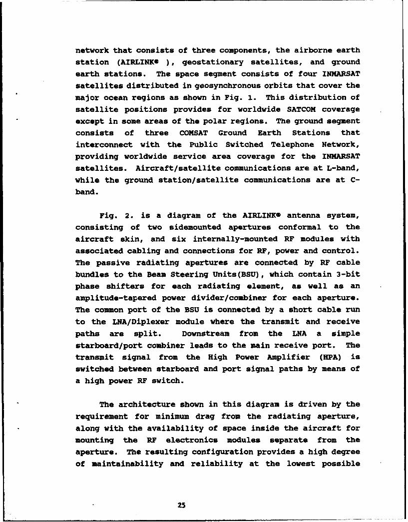
Fig. 2. is a diagram of the AIRLINKO antenna system,consisting of two sidemounted apertures conformal to theaircraft skin, and six internally-mounted RF modules withassociated cabling and connections for RF, power and control.
The passive radiating apertures are connected by RF cablebundles to the Beam Steering Units(BSU), which contain 3-bitphase shifters for each radiating element, as well as anamplitude-tapered power divider/combiner for each aperture.The common port of the BSU is connected by a short cable runto the LNA/Diplexer module where the transmit and receive
paths are split. Downstream from the LNA a simplestarboard/port combiner leads to the main receive port. Thetransmit signal from the High Power Amplifier (HPA) isswitched between starboard and port signal paths by means ofa high power RF switch.
The architecture shown in this diagram is driven by therequirement for minimum drag from the radiating aperture,along with the availability of space inside the aircraft formounting the RF electronics modules separate from theaperture. The resulting configuration provides a high degree
of maintainability and reliability at the lowest possiblet2
cost. Performance is compromised somewhat because of the
passive BSU circuitry and cabling between the aperture andLNA/diplexer.
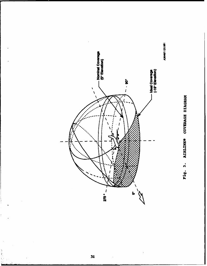
The coverage plan for the two sidemounted apertures isshown in Fig. 3. At a mounting angle of 450, the aperturecoverage overlaps at the zenith in a region (termedhysteresis) where a handoff routine between apertures isimplemented. As expected, low elevation coverage on the noseand tail is limited.
3. DUAL USE
In a more recent internal development at Ball Aerospace,the AIRLINK@ system has been reconfigured for secure militarycommunications. The system is designed to offer worldwide,clear, reliable, two-way, air-to-ground or ground-to-airsecure or non-secure voice and/or data communication. Thesecure interface unit of the audio/data subsystem performsanalog/digital signal conversions between the Secure TerminalUnit (STU-III) and the Satellite Data Units of the SATCOMtransceiver. The STU-III is an analog voice signal deviceused for both clear and secure voice and data communications.
The system is currently installed on a USAF Avionics TestBed aircraft for operations testing and evaluation. Numerousdeployments of the system are pending. Furthermore, thesystem is available for demonstration on a Ball Aerospacemobile test bed, which can demonstrate secure voice, video,FAX and PC transmissions.
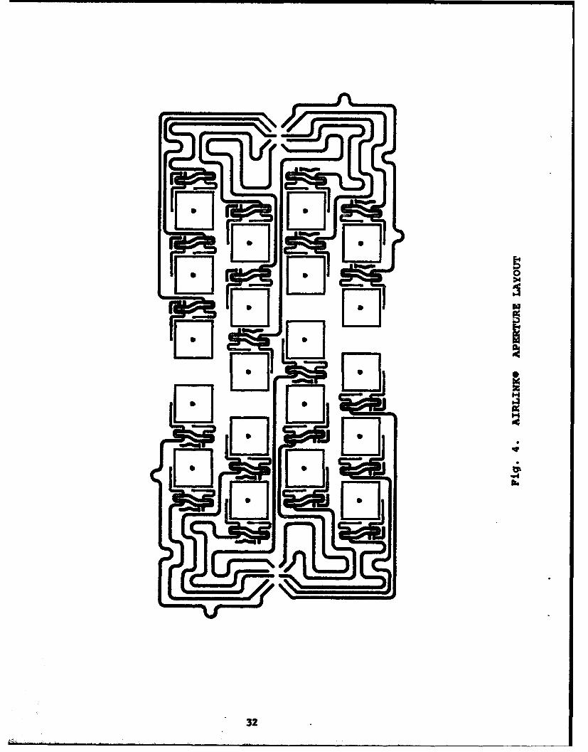
4. APERTURE DESCRIPTION
The multilayer printed circuit antenna aperture is shownin Fig. 4, in which the circuitry on four different layers aresuperimposed. It can be readily seen that the full available
26

aperture is not used, resulting in a some compromise inperformance. The space is used instead for the RF signallines from the bundled coaxial inputs to each radiatingelement. As shown below, this choice enhances the low costand producibility of the multilayer aperture. Both RF signallines and polarization hybrids are implemented in buriedmicrostrip, and are unshielded in the radiating aperture. Theradiating elements themselves are two-layer stacked microstrippatches, covering the full range of transmit and receivebandwidth (about 10%).
Fig. 5. is a cross-sectional view of the radiatingaperture, having a total thickness 0.375 in. The bottom layercontains the RF signal lines and the polarization hybrids, fedin a surface launch from the coaxial connectors in twobundles. Within the polarization hybrid the signal actuallyjumps from the trace layer on the bottom board to the backside of the lower (driver) element board, so that the feedribbon can be installed easily prior to any laminations. Theupper (driven) element is etched on a separate board, and theentire four-layer lamination (with a thin laminated radome) isaccomplished at one time.
The aperture assembly is about as simple as a multilayermicrostrip antenna can be. The installation of the twocoaxial connector bundles (shown in Fig. 6) is actually themost difficult part of the process. There were certainlydesign alternatives that would have provided marginallygreater performance, but at higher levels of complexity andproduction cost.
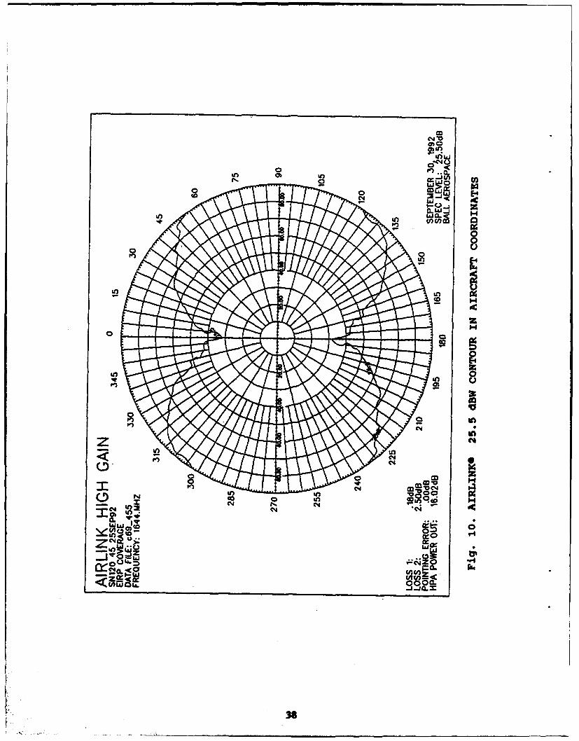
5. PERFORMANCE DATA
Pattern, gain, G/T and ERP data for the AIRLINKO antennasubsystem are shown in the following figures. Fig. 7. is atypical pattern plot with the antenna scanned to 450 along the
27

long (azimuth) dimension of the array. Testing andqualification of AIRLINKS also requires patterns where theantenna is constantly scanning as it rotates, so that the peakof beam points to the same angle. An example of this type ofpeak gain pattern is shown in Fig. 8. The same type ofscanning also produces contour plots from data taken overhalf-space. Fig. 9 is a plot of the 12.0 dBic gain contourfor AIRLINKO S/N 120. Single antenna data is also transformedinto aircraft coordinates for particular commissionings todetermine ERP and G/T coverage. Fig. 10 and 11 show aircraftcoverage contours at 25.5 dBW ERP and -13.0 dB/KO G/T.
28

j
I!, �
z 3
II*1I
I
II' 8
lou 0
S
I�Ww
'4
*14
p
Ia.'U
29

]E-40
14
IH
.02
300
i
L I0� ii
.3
IH0
N0
8S
a'.pgbe
I
31
ID iI
32

I I
I II * I
I I
I I
* I oIl
I I 01II m
I I I
I I a),I I I E
a) 0I I �II 0II m* I* I L2'is a)� -o
II a) s-II I o : *�I I J*.* a I* I I 0I I I,* II I III I II* I I* I II 02* I I* I II I I* I Ig 02
IIII
I I
II
I I I I.* I I� UI I I II I hi* I I I
* I
I I
I I I
* I
.1I I* II I -� Sn* I* I
I I 0.II
I 0.
I II I
* I. CII I a);
a)'WI
a).
33

I
I0I-8
04
34

U
C,,bo\0°- 00
0
7z ••r-- ~~~~~0
I.-L
S0,_Nu
N0 .
I--
~6 600
" " o o.. ' . r "" LO
I I I I I •
•-" 8P 3a .lfl-fld•~V
35

0
(n Cl)
00
0
0o
c<0
Lai 0<
7w0
z)P)0
004
oz-
c6 6l 6 L6 0~
e8P 3GfInindInv
36

C.)
0
Ul
4.1
C144
o 04
o -'
00
CLO U>*
z to
"Z 0 37
04,
00 ic
In4
zz
in0
I OR~ *~
go 0 S
N C44 if) 2.W$
Z C4 It-1o!9tl; -j-Jo.t
38

0 L0
ol
80 in
0
V
W) C0
z(4-
0 0
C4,
~CC4 r0 04 b
KN