electronics and microprocessors lab...
TRANSCRIPT

1
ECB 2182 ELECTRONICS AND MICROPROCESSORS LAB MANUAL
`
BY
S.SADHISH PRABHU,AP/ECE
DEPARTMENT OF ELECTRONICS & COMMUNICATION ENGINEERING

2
ECB 2182 ELECTRONICS AND MICROPROCESSORS LAB L T P C
0 0 3 1 LIST OF EXPERIMENTS ELECTRONICS EXPERIMENTS 15
1. VI Characteristics of PN Junction Diode
2. VI Characteristics of Zener Diode
3. Characteristics of CE Transistor
4. Characteristics of JFET
5. Characteristics of Uni Junction Transistor
DIGITAL EXPERIMENTS (12)
6. Study of Logic Gates (Basic Gates)
7. Half Adder and Full Adder
8. Shift Registers
9. 3 bit binary ripple counters
MICROPROCESSOR 18
1. 8 bit Addition, Subtraction
2. 16 bit addition and subtraction.
3. Multiplication and Division
4. Maximum and Minimum of block of data
5. Sorting and block transfer.
6. Stepper Motor Interfacing
TOTAL: 45

3
ELECTRONICS

4
EXPT. NO. : 1 PN JUNCTION DIODE CHARACTERISTICS DATE :
AIM :
i. To study the characteristics of PN junction diode under forward bias and reverse bias
condition.
ii. To plot the V-I characteristics of PN Junction diode.
iii. To find the static and dynamic resistance under forward bias and reverse bias condition
APPARATUS / COMPONENTS REQUIRED:
Sl.No. Apparatus Range Quantity
1. Regulated Power Supply (0-30)V 1
2. Ammeter (0-30)mA,(0-250)µA 1,1
3. Voltmeter (0-30)V,(0-1)V 1,1
4. Diode IN4001 1
5. Resistors 1kΩ,10KΩ 1,1
6. Bread Board
7. Connecting wires
THEORY:
The most important property of a junction diode is its ability to pass an electric current
in one direction only. When the p-type region of the p-n junction is connected to the positive
terminal of the battery, current will flow. The diode is said to be under forward bias. However,
when the battery terminals are reversed, the p-n junction almost completely blocks the current
flow. This is called reverse bias. If the diode is not connected at all, it is said to be open-
circuited and of course no current can flow through the diode. The application of a forward bias
voltage to a junction diode reduces the barrier potential. The majority carrier diffuses across the
junction. This causes the current to flow across the diode. In reverse biased condition the barrier
potential increases so that almost no current flows through the diode. However, a very small
reverse current does flow. This reverse saturation current depends only on the thermal

5
generation of holes and electrons near the junction, not on the height of the potential barrier. In
practice, this reverse saturation current is quite small but it increases with increasing
temperature. However, all diodes have a maximum reverse voltage (usually 50V or more) and if
this is exceeded the diode will fail and pass a large current in the reverse direction, this is called
breakdown.
For IN 4001 the Maximum reverse voltage and maximum reverse current are 50V and
1A respectively.
EXPERIMENT PROCEDURE:
Forward Bias Characteristics
1. Connect the circuit as per the circuit diagram
2. Vary the power supply in such a way that the reading are taken in steps of 0.1 v
3. Note the corresponding ammeter reading.
4. Plot the graph V against I.
5. From the plot find the static resistance and dynamic resistance
Static resistance rs=V/I
Dynamic resistance rd=∆v/∆I
Reverse Bias Characteristics
1. Connect the circuit as per the circuit diagram
2. Vary the power supply in steps of 1V till the voltmeter reads 20v
3. Note the corresponding ammeter reading.
4. Plot the graph V against I.
5. From the plot find the static resistance and dynamic resistance
Static resistance rs=V/I
Dynamic resistance rd=∆v/∆I

6
CIRCUIT DIAGRAM:
Forward Bias
Reverse Bias
SYMBOL MODEL GRAPH

7
TABULAR COLUMN:
Sl.No.
Forward Bias Reverse Bias
Forward
Voltage (Vf)
(volt)
Forward Current
(If)
(mA)
Reverse
voltage(Vr)
(volt)
Reverse
Current(Ir)
(µA)
RESULT:
Thus the forward and reverse characteristics of PN junction diode was plotted and their
corresponding static and dynamic resistance was found
Forward Bias Reverse Bias
Static resistance rs= ------------------ Static resistance rs= ------------------
Dynamic resistance rd= ------------------ Dynamic resistance rd= ------------------
Mark spilt up:
Preparation (25)
Execution (20)
Lab Performance(10)
Viva (20)
Total (75)

8
EXPT. NO. : 2 ZENER DIODE CHARACTERISTICS DATE :
AIM :
i. To study the characteristics of Zener diode under forward bias and reverse bias
condition.
ii. To plot the V-I characteristics of Zener diode.
iii. To find the static and dynamic resistance under forward bias and reverse bias condition
APPARATUS / COMPONENTS REQUIRED:
Sl.No. Apparatus Range Quantity
1. Regulated Power Supply (0-30)V 1
2. Ammeter (0-30)mA 1,1
3. Voltmeter (0-30)V,(0-1)V 1,1
4. Diode FZ 5.6v 1
5. Resistors 1kΩ,10KΩ 1,1
6. Bread Board
7. Connecting Wires
THEORY:
Zener diode is a special diode with increased amounts of doping. This is to compensate
for the damage that occurs in the case of a pn junction diode when the reverse bias exceeds the
breakdown voltage and thereby current increases at a rapid rate. The forward characteristic of
the Zener diode is same as that of a pn junction diode i.e. as the applied potential increases the
current increases exponentially. As the reverse bias increases the current increases rapidly in a
direction opposite to that of the positive voltage region. Thus under reverse bias condition
breakdown occurs. It occurs because there is a strong electric filed in the region of the junction
that can disrupt the bonding forces within the atom and generate carriers. The breakdown
voltage depends upon the amount of doping. For a heavily doped diode depletion layer will be
thin and breakdown occurs at low reverse voltage and the breakdown voltage is sharp. Whereas
lightly doped diode has a higher breakdown voltage. The maximum reverse bias potential that

9
can be applied before entering the Zener region is called the Peak Inverse Voltage referred to as
PIV rating or the Peak Reverse Voltage Rating (PRV rating).For FZ5.6v Zener diode the break
down occurs at 5.6 V
EXPERIMENT PROCEDURE:
Forward Bias
1. Connect the circuit as per the circuit diagram
2. Vary the power supply in such a way that the reading are taken in steps of 0.1 v
3. Note the corresponding ammeter reading.
4. Plot the graph V against I.
5. From the plot find the static resistance and dynamic resistance
Static resistance rs=V/I
Dynamic resistance rd=∆v/∆I
Reverse Bias
1. Connect the circuit as per the circuit diagram
2. Vary the power supply in steps of 1V till the voltmeter reads 20v
3. Note the corresponding ammeter reading.
4. Plot the graph V against I.
5. From the plot find the static resistance and dynamic resistance
Static resistance rs=V/I
Dynamic resistance rd=∆v/∆I
CIRCUIT DIAGRAM:
Forward Bias

10
Reverse Bias
SYMBOL MODEL GRAPH
TABULAR COLUMN:
Sl.No.
Forward Bias Reverse Bias
Forward
Voltage (Vf)
(volt)
Forward
Current (If)
(mA)
Reverse
voltage(Vr)
(volt)
Reverse
Current(Ir)
(µA)

11
RESULT:
Thus the forward and reverse characteristics of PN junction diode was plotted and their
corresponding static and dynamic resistance was found
Forward Bias Reverse Bias
Static resistance rs= ------------------ Static resistance rs= ------------------
Dynamic resistance rd= ------------------ Dynamic resistance rd= ------------------
Mark spilt up:
Preparation (25)
Execution (20)
Lab Performance(10)
Viva (20)
Total (75)

12
EXPT. NO. : 3 INPUT AND OUTPUT CHARACTERISTICS OF BJT IN CE CONFIGURATION
DATE :
AIM:
i. To plot the input and output characteristics of BJT in CE configuration
ii. To determine the h- parameter experimentally
APPARATUS / COMPONENTS REQUIRED :
Sl.No. Apparatus Range Quantity
1. Regulated Power Supply (0-30)V 1
2. Voltmeter (0-1)V,(0-30)V 1,1
3. Ammeter (0-500)μA,(0-30)mA 1,1
4. BJT BC107/BC147 1
5. Resistors 1KΩ 2
6. Bread Board
7. Connecting Wires
THEORY:
A transistor is a three terminal device. It can be considered as the combination of two
diodes. In a t ransistor there are 3 regions: 1.emitter 2.base 3.Collector. In an npn transistor the
emitter and collector are n types, and base is p type. In any transistor emitter is heavily doped,
base is lightly doped and collector is moderately doped. For the proper working of transistor the
emitter base junction should be forward biased and collector base junction should be reverse
biased.
In a common emitter configuration, emitter is common to both input and output. the
common emitter current gain ß can be calculated as a ratio between collector current and base
current at a p articular value of output voltage (collector emitter voltage). The input

13
characteristics are a plot between the base current and base emitter voltage. The dynamic input
resistance can be calculated by taking the slope of the input characteristics by keeping the
output voltage constant. The output characteristic is a plot between collector current and
collector emitter voltage by keeping the input current constant.
EXPERIMENT PROCEDURE:
Input characteristics
1. Connect the circuit as per the circuit diagram
2. Set VCE at 0V, vary VBE in steps of 0.1 V and note down the corresponding base current
IB value
3. Plot the graph between VBE and IE
4. Repeat the above procedure for VCE=5V
5. From the characteristics curve, the h-parameters is given by
hie = ∆VBE/∆IB Ω │VCE is constant
hre = ∆VBE/∆VCE │IB is constant (no unit)
Output characteristics
1. Set IB at 20µA by suitable voltage at the base terminal.
2. Vary VCE in steps of 1V and note down the corresponding collector current IC value
3. Plot the graph between VCE and IC
4. Repeat the procedure for IB=40µA and IB=60µA
5. From the characteristics curve, the h-parameters is given by
hoe = ∆IC/∆VCE mho │IB is constant
hfe = ∆IC/∆IB│VCE is constant(no unit)
CIRCUIT DIAGRAM:

14
SYMBOL BASE DIAGRAM
MODEL GRAPH Input Characteristics Output Characteristics
TABULAR COLUMN:
VBE
(volt)
IB(µA)
VCE =0V VCE = 5V
VCE
(volt)
IC(mA)
IB=20µA IB=40µA IB=60µA
Input Characteristics Output Characteristics

15
RESULT :
Thus the input and output characteristics of BJT in CE configuration was studied and h-
parameters were found
hie = ------------------------- hoe = ---------------------------
hre = ------------------------ hfe = ---------------------------
Mark spilt up:
Preparation (25)
Execution (20)
Lab Performance(10)
Viva (20)
Total (75)

16
EXPT. NO. : 4 CHARACTERISTICS OF JFET DATE :
AIM:
i. To plot the drain and transfer characteristics of JFET
ii. To find the drain resistance transconductance and amplification factor.
APPARATUS / COMPONENTS REQUIRED:
Sl.No. Apparatus Range Quantity
1. Regulated Power Supply (0-30)V 1
2. Voltmeter (0-30)V 2
3. Ammeter (0-30)mA 1
4. FET BFW10 1
5. Resistors 68KΩ,1KΩ 1,1
6. Bread Board
7. Connecting Wires
THEORY:
The Junction Field-Effect Transistor (JFET) is a device providing a controlled transport
of majority carriers through a s emiconductor. The FET is a d evice in which flow of current
through the conducting region is controlled by an electric field. Hence the name Field Effect
Transistor. As current conduction is only majority carriers FET is said to be uni-polar device. It
is a three terminal device namely source drain and the control terminal gate.
The plot of ID versus VDS for different values of gate source voltage VGS is called Drain
characteristics. Consider first VGS=0 V for small values of VDS, the drain current ID increases
linearly called ohmic region. For larger values, the increase of ID is nonlinear until pinch-off
voltage (Vp) occurs After pinch-off, ID cannot increase further, and stays constant at the value

17
IDSS called saturation region. Now decrease vGS to a negative value. Then pinch-off occurs at a
lower value of VDS..If VGS is reduced to the negative value Vp, then ID=0 and current flow is cut-
off. The plot of ID versus VGS is called transfer characteristics. The slope of ID-VGS will give the
important parameter transconductance gm. of FET.
EXPERIMENT PROCEDURE:
Drain Characteristics
1. Connect the circuit as per the circuit diagram.
2. Set gate source voltage VGS = 0V.Vary the drain source voltage VDS in steps of 1V and
note down the corresponding drain current ID
3. Repeat the above procedure for VGS=-1V and -2V
4. Plot the graph for VDS versus ID for different constant values of VGS
5. Find the drain resistance rd =∆VDS/∆ID
Transfer Characteristics
1. Set the drain source voltage VDS = +5V and vary the gate source voltage VGS in steps of
1V and note corresponding drain current ID
2. Repeat the above procedure for VDS=10V and 15V
3. Plot the graph for VGS versus ID for different constant values of VDS
4. Find the transconductance gm=∆ID/∆VGS
5. find the amplification factor µ=gm x rd.
CIRCUIT DIAGRAM:

18
SYMBOL BASE DIAGRAM
MODEL GRAPH
Drain Characteristics Transfer Characteristics
VGS
(volt)
ID(mA)
VDS = 5V VDS= 10V
VDS
(volt)
ID(mA)
VGS = 0V VGS=-1V VGS = -2V
Drain Characteristics Transfer Characteristics
TABULAR COLUMN:

19
RESULT:
Thus the Drain and Transfer characteristics of FET was studied and the parameters drain
resistance, transconductane and amplification factor were found
Drain resistance rd=--------------------- Transconductance gm=--------------------------
Amplification factor µ=----------------------
Mark spilt up:
Preparation (25)
Execution (20)
Lab Performance(10)
Viva (20)
Total (75)

20
EXPT. NO. : 5 UJT CHARACTERISTICS DATE :
AIM:
i. To plot the V-I characteristics of UJT
ii. To determine the intrinsic stand off ratio η of the UJT
APPARATUS / COMPONENTS REQUIRED:
Sl.No. Apparatus Range Quantity
1. Regulated Power Supply (0-30)V 1
2. Voltmeter (0-30)V 2
3. Ammeter (0-30)mA 1
4. UJT 2N2646 1
5. Resistors 1KΩ 1
6. Bread Board
7. Connecting Wires
THEORY:
UJT is a device which does not belong to thyristor family but it is used to turn ON
SCRs. UJT means Uni (having one PN junction) and three terminals like transistors The three
terminals are Base1, Base2 and emitter.
A p-type material which is heavily doped is used to form PN junction at the boundary of
the aluminum rod and n-type silicon slab which is lightly doped. The emitter (E) is taken out
from this p-type material. The equivalent circuit consist of a diode(PN junction) with interbase
resistance between B2 and B1 of silicon bar .The internal resistance of the two bases are
represented as RB1 and RB2 .In the actual construction the terminal E is closer to B2 as compares
to B1 . Hence the resistance RB1 is more than the resistance RB2 The total resistance is
RBB=RB1+RB2.

21
The UJT characteristics consist of three regions
• Cut-off region: Leakage current flows from base 2(B2) to emitter (E) when VE increases
from zero.
• Negative resistance region: after peak point Vp there is increase in current with decrease
in voltage.
• Saturation region: after Valley point Vv the device will drive into saturation.
Since the UJT has current controlled negative resistance characteristics it is used in applications
like sawtooth wave generator, pulse generator etc.
PROCEDURE:
1. Connect the circuit as per the circuit diagram.
2. Set VBB=5V, Vary VEE from 0V slowly in steps of of 1V and note down the
corresponding values of VEB and IE
3. Increase the voltage to get the Valley point.
4. Plot the graph of IE versus VE
5. Determine the intrinsic stand off ratio
η= VP - Vv /VBB
CIRCUIT DIAGRAM:

22
SYMBOL BASE DIAGRAM MODEL GRAPH
TABULAR COLUMN:
VBB
(volt)
IE
(mA)
VEB
(volt)
5
10
15
RESULT:
Thus the characteristics of given UJT is found and the intrinsic stand off ratio is
determined
η= ---------------------------
Mark spilt up:
Preparation (25)
Execution (20)
Lab Performance(10)
Viva (20)
Total (75)

23
EXPT. NO. : 6 STUDY OF LOGIC GATES DATE : AIM:
To study about logic gates and verify their truth tables.
APPARATUS REQUIRED:
THEORY: Circuit that takes the logical decision and the process are called logic gates. Each gate
has one or more input and only one output.
OR, AND a nd NOT are basic gates. NAND, NOR and X-OR are known as universal
gates. Basic gates form these gates.
AND GATE: The AND gate performs a logical multiplication commonly known as AND function.
The output is high when both the inputs are high. The output is low level when any one of the
inputs is low.
OR GATE: The OR gate performs a logical addition commonly known as OR function. The
output is high when any one of the inputs is high. The output is low level when both the inputs
are low.
SL No. COMPONENT SPECIFICATION QTY 1. AND GATE IC 7408 1 2. OR GATE IC 7432 1 3. NOT GATE IC 7404 1 4. NAND GATE 2 I/P IC 7400 1 5. NOR GATE IC 7402 1 6. X-OR GATE IC 7486 1 7. NAND GATE 3 I/P IC 7410 1 8. IC TRAINER KIT - 1 9. PATCH CORD - 14

24
NOT GATE: The NOT gate is called an inverter. The output is high when the input is low. The
output is low when the input is high.
NAND GATE:
The NAND gate is a contraction of AND-NOT. The output is high when both inputs are
low and any one of the input is low .The output is low level when both inputs are high.
NOR GATE: The NOR gate is a contraction of OR-NOT. The output is high when both inputs are
low. The output is low when one or both inputs are high.
X-OR GATE: The output is high when any one of the inputs is high. The output is low when both the
inputs are low and both the inputs are high.
PROCEDURE: (i) Connections are given as per circuit diagram.
(ii) Logical inputs are given as per circuit diagram.
(iii) Observe the output and verify the truth table.
AND GATE: SYMBOL: PIN DIAGRAM:

25
OR GATE:
NOT GATE: SYMBOL: PIN DIAGRAM:

26
X-OR GATE : SYMBOL : PIN DIAGRAM :
2-INPUT NAND GATE: SYMBOL: PIN DIAGRAM:

27
3-INPUT NAND GATE :
NOR GATE:

28
RESULT: Thus the logic gates were studied and their truth table were verified Mark spilt up:
Preparation (25)
Execution (20)
Lab Performance(10)
Viva (20)
Total (75)
29
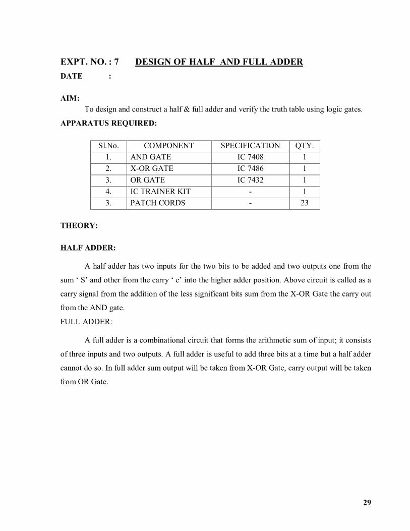
EXPT. NO. : 7 DESIGN OF HALF AND FULL ADDER DATE : AIM:
To design and construct a half & full adder and verify the truth table using logic gates.
APPARATUS REQUIRED:
Sl.No. COMPONENT SPECIFICATION QTY. 1. AND GATE IC 7408 1 2. X-OR GATE IC 7486 1 3. OR GATE IC 7432 1 4. IC TRAINER KIT - 1 3. PATCH CORDS - 23
THEORY:
HALF ADDER:
A half adder has two inputs for the two bits to be added and two outputs one from the
sum ‘ S’ and other from the carry ‘ c’ into the higher adder position. Above circuit is called as a
carry signal from the addition of the less significant bits sum from the X-OR Gate the carry out
from the AND gate.
FULL ADDER:
A full adder is a combinational circuit that forms the arithmetic sum of input; it consists
of three inputs and two outputs. A full adder is useful to add three bits at a time but a half adder
cannot do so. In full adder sum output will be taken from X-OR Gate, carry output will be taken
from OR Gate.

30
LOGIC DIAGRAM: HALF ADDER
TRUTH TABLE:
A B CARRY SUM
0 0 1 1
0 1 0 1
0 0 0 1
0 1 1 0
K-Map for SUM: K-Map for CARRY:
SUM = A’B + AB’ CARRY = AB LOGIC DIAGRAM: FULL ADDER FULL ADDER USING TWO HALF ADDER

31
TRUTH TABLE:
A B C CARRY SUM 0 0 0 0 1 1 1 1
0 0 1 1 0 0 1 1
0 1 0 1 0 1 0 1
0 0 0 1 0 1 1 1
0 1 1 0 1 0 0 1
K-Map for SUM:
SUM = A’B’C + A’BC’ + ABC’ + ABC K-Map for CARRY:
CARRY = AB + BC + AC

32
PROCEDURE: (i) Connections are given as per circuit diagram.
(ii) Logical inputs are given as per circuit diagram.
(iii) Observe the output and verify the truth table.
RESULT:
Thus the half and full adder were designed and verified.
Mark spilt up:
Preparation (25)
Execution (20)
Lab Performance(10)
Viva (20)
Total (75)

33
EXPT. NO. : 8 DESIGN AND IMPLEMENTATION OF SHIFT REGISTER DATE : AIM:
To design and implement (i) Serial in serial out (ii) Parallel in parallel out
APPARATUS REQUIRED:
Sl.No. COMPONENT SPECIFICATION QTY. 1. D FLIP FLOP IC 7474 2 2. OR GATE IC 7432 1 3. IC TRAINER KIT - 1 4. PATCH CORDS - 35
THEORY:
A register is capable of shifting its binary information in one or both directions is known
as shift register. The logical configuration of shift register consist of a D-Flip flop cascaded with
output of one flip flop connected to input of next flip flop. All flip flops receive common clock
pulses which causes the shift in the output of the flip flop. The simplest possible shift register
is one that uses only flip flop. The output of a given flip flop is connected to the input of next
flip flop of the register. Each clock pulse shifts the content of register one bit position to right.
PIN DIAGRAM:

34
LOGIC DIAGRAM:
SERIAL IN SERIAL OUT:
TRUTH TABLE:
CLK Serial in Serial out
1 1 0
2 0 0
3 0 0
4 1 1
5 X 0
6 X 0
7 X 1
LOGIC DIAGRAM:
PARALLEL IN PARALLEL OUT:

35
TRUTH TABLE:
CLK
DATA INPUT OUTPUT
DA DB DC DD QA QB QC QD
1 1 0 0 1 1 0 0 1
2 1 0 1 0 1 0 1 0
PROCEDURE:
(i) Connections are given as per circuit diagram.
(ii) Logical inputs are given as per circuit diagram.
(iii) Observe the output and verify the truth table.
RESULT: Thus the SISO and PIPO shift registers were designed and implemented .
Mark spilt up:
Preparation (25)
Execution (20)
Lab Performance(10)
Viva (20)
Total (75)

36
EXPT. NO. : 9 CONSTRUCTION AND VERIFICATION OF 4 BIT RIPPLE COUNTER
DATE : AIM: To design and verify 4 bit ripple counter.
APPARATUS REQUIRED:
Sl.No. COMPONENT SPECIFICATION QTY.
1. JK FLIP FLOP IC 7476 2 2. NAND GATE IC 7400 1 3. IC TRAINER KIT - 1 4. PATCH CORDS - 30
THEORY:
A counter is a register capable of counting number of clock pulse arriving at its clock
input. Counter represents the number of clock pulses arrived. A specified sequence of states
appears as counter output. This is the main difference between a register and a counter. There
are two types of counter, synchronous and asynchronous. In synchronous common clock is
given to all flip flop and in asynchronous first flip flop is clocked by external pulse and then
each successive flip flop is clocked by Q or Q output of previous stage. A soon the clock of
second stage is triggered by output of first stage. Because of inherent propagation delay time all
flip flops are not activated at same time which results in asynchronous operation.
PIN DIAGRAM FOR IC 7476:

37
LOGIC DIAGRAM FOR 4 BIT RIPPLE
COUNTER:
TRUTH TABLE:
CLK QA QB QC QD
0 0 0 0 0
1 1 0 0 0
2 0 1 0 0
3 1 1 0 0
4 0 0 1 0
5 1 0 1 0
6 0 1 1 0
7 1 1 1 0
8 0 0 0 1
9 1 0 0 1
10 0 1 0 1
11 1 1 0 1
12 0 0 1 1
13 1 0 1 1
14 0 1 1 1
15 1 1 1 1

38
PROCEDURE:
(i) Connections are given as per circuit diagram.
(ii) Logical inputs are given as per circuit diagram.
(iii) Observe the output and verify the truth table.
RESULT: Thus a 4 bit ripple counter was designed and verified. Mark spilt up:
Preparation (25)
Execution (20)
Lab Performance(10)
Viva (20)
Total (75)

39
MICROPROCESSOR

40
EXPT. NO. : 10 8 BIT ADDITION AND SUBTRACTION DATE : AIM: To write an assembly language program to perform 8 bit addition and subtraction using 8085 trainer kit. ALGORITHM:
(i) 8 Bit Addition
1. Initialize memory pointer to data location.
2. Get the first number from memory in accumulator.
3. Get the second number and add it to the accumulator.
4. Store the answer at another memory location.
(ii) 8 Bit Subtraction
1. Initialize memory pointer to data location.
2. Get the first number from memory in accumulator.
3. Get the second number and subtract from the accumulator.
4. If the result yields a borrow, the content of the acc. is complemented and 01H is added
to it (2’s complement). A register is cleared and the content of that reg. is incremented in
case there is a borrow. If there is no borrow the content of the acc. is directly taken as
the result.
5. Store the answer at next memory location.

41
PROGRAM:
(i) 8 Bit Addition ADDRESS OPCODE LABEL MNEMONICS OPERAND COMMENT
4100 START MVI C, 00 Clear C reg. 4101 4102 LXI H, 4500 Initialize HL reg. to
4500 4103 4104 4105 MOV A, M Transfer first data to
accumulator 4106 INX H Increment HL reg. to
point next memory Location.
4107 ADD M Add first number to acc. Content.
4108 JNC L1 Jump to location if result does not yield
carry. 4109 410A 410B INR C Increment C reg. 410C L1 INX H Increment HL reg. to
point next memory Location.
410D MOV M, A Transfer the result from acc. to memory.
410E INX H Increment HL reg. to point next memory
Location. 410F MOV M, C Move carry to memory 4110 HLT Stop the program
OBSERVATION:
INPUT OUTPUT 4500 4502 4501 4503

42
(ii) 8 Bit Subtraction
ADDRESS OPCODE LABEL MNEMONICS OPERAND COMMENT
4100 START MVI C, 00 Clear C reg. 4102 4102 LXI H, 4500 Initialize HL reg. to
4500 4103 4104 4105 MOV A, M Transfer first data to
accumulator 4106 INX H Increment HL reg. to
point next mem. Location.
4107 SUB M Subtract first number from acc. Content.
4108 JNC L1 Jump to location if result does not yield
borrow. 4109 410A 410B INR C Increment C reg. 410C CMA Complement the Acc.
content 410D ADI 01H Add 01H to content of
acc. 410E 410F L1 INX H Increment HL reg. to
point next mem. Location.
4110 MOV M, A Transfer the result from acc. to memory.
4111 INX H Increment HL reg. to point next mem.
Location. 4112 MOV M, C Move carry to mem. 4113 HLT Stop the program

43
OBSERVATION:
INPUT OUTPUT 4500 4502 4501 4503
RESULT: Thus an assembly language program to perform 8 bit addition and subtraction using 8085 trainer kit was written and executed. Mark spilt up:
Preparation (25)
Execution (20)
Lab Performance(10)
Viva (20)
Total (75)

44
EXPT. NO. :11 16 BIT ADDITION AND SUBTRACTION DATE : AIM:
To write an assembly language program for the addition and subtraction of two 16-bit numbers, using 8085. ALGORITHM: (i) 16 BIT ADDITION
1. Start the program. 2. Clear the B-register. 3. Load the Data1 to HL register pair. 4. Exchange the content of HL to the DE register pair. 5. Load the Data2 to HL pair register. 6. Add the content of HL and DE pair. 7. If no overflow in addition (no carry), go to step 9. 8. Increment the content of B-register. 9. Store the content of HL pair to the address 5504H. 10. Store the content of B-register to the address 5506H. 11. Stop the program. (ii) 16 BIT SUBTRACTION 1. Start the program. 2. Load the Data2 to HL register pair. 3. Exchange the content of HL to the DE register pair. 4. Load the Data1 to HL register pair. 5. Move the content of L register to Accumulator. 6. Subtract the content of E register from the Accumulator. 7. Store the result in accumulator to the memory location, 5100H. 8. Move the content of H register to Accumulator. 9. Subtract the content of D register from the Accumulator, along with borrow. 10. Store the result in Accumulator to the memory location, 5101H. 11. Stop the program.

45
PROGRAM: (i) 16 BIT ADDITION
(ii) 16 BIT SUBTRACTION

46
OBSERVATION: (i) 16 BIT ADDITION
(ii) 16 BIT SUBTRACTION
RESULT:
Thus an assembly language program for the addition and subtraction of two 16-bit numbers, using 8085 was written and executed. Mark spilt up:
Preparation (25)
Execution (20)
Lab Performance(10)
Viva (20)
Total (75)

47
EXPT. NO. : 12 MULTIPLICATION AND DIVISION DATE : AIM: To write an ALP to perform the following operations using 8085
a) 8 bit multiplication a nd b) 8 bit division
a) 8 bit multiplication ALGORITHM:
1. Get the multiplier and multiplicand from the memory 2. Initialize register pair=0000 3. Perform double addition as register pair = register pair + multiplicand 4. Decrement multiplier as multiplier = multiplier-1 5. Is multiplier=0, if yes go to step 6 otherwise go to step 3 6. Store the contents of the register pair in the memory location 7. Stop.
PROGRAM: LABEL ADDRESS MNEMONICS OPCODE COMMENTS
4100 LDA 4502 3A 02 45 Load multiplier and get the multiplier to B 4103 MOV B, A 47
4104 LXI D, 0000 H 11 00 00 Load multiplicand in DE 4107 LHLD 4500 2A 00 45
410A XCHG EB L1: 410B DAD D 19
If not zero loop again. Else store the result
410C DCR B 05 410D JNZ L1 C2 0B 41 4110 SHLD 5000 22 00 50 4113 HLT 76
BEFORE EXECUTION AFTER EXECUTION ADDRESS DATA
4500
4501 4502 4503
ADDRESS DATA 4500 4501 4502 4503 5000 5002

48
(b) 8 bit division
ALGORITHM:
1. Load the divisor to register B and dividend to A reg 2. Initialize quotient = 0 3. Its dividend<divisor , if yes go to step 7 otherwise go to step 4 4. Dividend = dividend – divisor 5. Quotient = quotient+1 6. Is dividend < divisor, if yes go to step 7 otherwise go to step 4 7. Store the quotient and reminder(=dividend now) 8. Stop.
PROGRAM: LABEL ADDRESS MNEMONICS OPCODE COMMENTS
4100 LDA 4500 3A 00 15 Load the content in A register
4103 MOV B, A 47 Move the A register to B register
4104 LDA 4502 3A 02 45 Load the A register
4107 MVI C, 00 0E 00 00 is loaded immediately in C register
L2 4109 CMP B B8 Compare the two register content
410A JC L1 DA 12 41 Jump on carry to location L1 410D SUB B 90 Subtract the B register content 410E INR C 0C Increment the C register 410F JMP L2 C3 09 41 Jump to location L2
L1 4112 STA 5000 32 00 50 Store the result 4115 MOV A, C 79 Move the content to A register 4116 STA 5002 32 02 50 Store the content in 5002 4119 HLT 76 Stop

49
BEFORE EXECUTION AFTER EXECUTION
RESULT: Thus an ALP to perform the 8 bit multiplication and division using 8085 was written and
executed
Mark spilt up:
Preparation (25)
Execution (20)
Lab Performance(10)
Viva (20)
Total (75)
ADDRESS DATA 4500 4502
ADDRESS DATA 4500 4502 5000 5002

50
EXPT. NO. : 13 LARGEST AND SMALLEST NUMBERS DATE : AIM: To write an ALP to find the largest and the smallest number in an array of data using
8085 instruction set.
(a) LARGEST NUMBER
ALGORITHM: 1. Load the count for the size of the array. 2. Get the first value 3. Get the next value from the memory. 4. Compare those two values 5. Check for carry 6. If there is no carry decrement the count and check whether zero is occurred, if it is zero
store the largest number if not proceed from step 3. 7. If there is carry shift the content from the memory to the accumulator and proceed from
step 6. 8. End of program.
PROGRAM: LABEL ADDRESS MNEMONICS OPCODE COMMENTS
4100 LDA 4150 3A 50 41 Load the A reg 4103 MOV C,A 46 Move the data form A reg
to C reg 4104 DCR C 0D Decrement the C reg 4105 LXI H,4151 21 41 51 Load the HL pair with
4151 4108 MOV A,M 7E Move the content from the
Memory to the A reg L2 4109 INX H 23 Increment the HL reg pair
410A CMP M BE Compare the Memory content with the A reg
410B JNC L1 D2 0F 41 Jump on no carry to L1 410C MOV A,M 7E Move the content from M
to A L1 410D DCR C 0D Decrement the C reg
content 4110 JNZ L2 C2 09 41 Jump on no zero to L2 4113 STA 5000 32 00 50 Store the A reg content to
5000 4116 HLT 76 Stop

51
BEFORE EXECUTION AFTER EXECUTION
(b) SMALLEST NUMBER
ALGORITHM: 1. Load the count for the size of the array. 2. Get the first value 3. Get the next value from the memory. 4. Compare those two values 5. Check for carry 6. If there is carry decrement the count and check whether zero is occurred, if it is zero
store the largest number if not proceed from step 3. 7. If there is no carry shift the content from the memory to the accumulator and proceed
from step 6. 8. End of program.
PROGRAM: LABEL ADDRESS MNEMONICS OPCODE COMMENTS
4100 LDA 4150 3A 50 41 Load the A reg 4103 MOV C,A 46 Move the data form A reg
to C reg 4104 DCR C 0D Decrement the C reg 4105 LXI H,4151 21 41 51 Load the HL pair with
4151 4108 MOV A,M 7E Move the content from the
Memory to the A reg L2 4109 INX H 23 Increment the HL reg pair
410A CMP M BE Compare the Memory content with the A reg
410B JC L1 D2 0F 41 Jump on carry to L1 410C MOV A,M 7E Move the content from M
to A L1 410D DCR C 0D Decrement the C reg
content 4110 JNZ L2 C2 09 41 Jump on no zero to L2 4113 STA 5000 32 00 50 Store the A reg content to
5000 4116 HLT 76 Stop
ADDRESS DATA 4200 04 (COUNT) 4201 02 4202 03 4203 04 4204 05
ADDRESS DATA 5058 05

52
BEFORE EXECUTION AFTER EXECUTION
RESULT: Thus an assembly language program was written and executed to find the largest and smallest number in an array Mark spilt up:
Preparation (25)
Execution (20)
Lab Performance(10)
Viva (20)
Total (75)
ADDRESS DATA 4200 04 (COUNT) 4201 02 4202 03 4203 04 4204 05
ADDRESS DATA 5000 02

53
RESULT: EXPT. NO. : 14 BLOCK TRANSFER DATE : AIM:
Write a program to transfer block of bytes from location 4040 to 4050. Block length is stored at
403F.
LOGIC:
Block length is copied from location 403F and is used as counter. Data from memory location
4040 is copied to accumulator and from accumulator to 4050.After data is copied pointers for
source and destination block is incremented by one and counter is decremented. Procedure is
repeated till counter is not zero.
ALGORITHM:
1. Start
2. Copy length of block
3. Initialize memory pointer of source block
4. Initialize memory pointer of destination block
5. Copy content of memory location from source block to accumulator
6. Copy content of memory location from accumulator to destination block
7. Increment both pointers
8. Decrement counter
9. If counter is not zero go to step 5
10. Stop

54
PROGRAM:
OBSERVATION:
RESULT: Thus and ALP was written to transfer block of bytes from location 4040 to 4050 Mark spilt up:
Preparation (25)
Execution (20)
Lab Performance(10)
Viva (20)
Total (75)

55
EXPT. NO. :15 SORTING PROGRAM (ASCENDING AND DESCENDING ORDER) DATE : AIM:
To write an assembly language program for arrange an array of 8-bit numbers in ascending and descending order, using 8085. ALGORITHM: ASCENDING ORDER: ALGORITHM:
1. Load the count value from memory to A reg. and save it in B register. 2. Decrement B register ( B is a count for N-1 repetitions) 3. Set HL pair as data array address pointer. 4. Set C – register as counter for N-1 comparisons 5. Load a data of the array in accumulator using the data address pointer 6. Increment the HL register pair content 7. Compare the data pointed by the HL register pair with accumulator 8. If carry flag is set (if the content of the accumulator is small than the memory content)
then go to step10 otherwise go to the next step. 9. Exchange the content of memory pointed by HL and the accumulator. 10. Decrement the C register. If zero flag is reset go to step 6 otherwise go to the next step. 11. Decrement the B register. If zero flag is reset go to step 3 otherwise go to the next step. 12. Stop

56
PROGRAM: LABEL ADDRESS MNEMONICS OPCODE COMMENTS
4100 LDA 4200 3A 00 42 Load the count value in the A register
4103 MOV B, A 47 Set count for N-1 repetitions 4104 DCR B 05 N-1 comparisons
LOOP2: 4105 LXI H, 4200 21 00 42 Load the HL register pair with 4500
4108 MOV C, M 4E Move the content from memory to C register
4109 DCR C 0D Decrement the C register 410A INX H 23 Increment the Hl register
pair LOOP1: 410B MOV A, M 7E Move the memory content
to A register 410C INX H 23 Increment the HL register
Pair 410D CMP M BE Compare the memory
content with the accumulator
410E JC LOOP DA 16 41 Jump on carry to loop 4111 MOV D,M 56 Move the content from
memory to D register 4112 MOV M,A 77 Move the A reg content to
memory 4113 DCX H 2B Decrement the HL register 4114 MOV M,D 72 Move the D register content
to memory 4115 INX H 23 Increment the HL register
pair LOOP: 4116 DCR C 0D Decrement the C register
4117 JNZ LOOP1 C2 0B 41 Jump on no zero to loop1 411A DCR B 05 Decrement the B register 411B JNZ LOOP2 C2 05 41 Jump on no zero to loop2 411E HLT 76 Stop
BEFORE EXECUTION AFTER EXECUTION
ADDRESS DATA 4200 04 (COUNT) 4201 05 4202 04 4203 03 4204 02
ADDRESS DATA 4200 04 (COUNT) 4201 02 4202 03 4203 04 4204 05

57
DESCENDING ORDER: ALGORITHM:
1. Load the count value from memory to A reg. and save it in B register. 2. Decrement B register ( B is a count for N-1 repetitions) 3. Set HL pair as data array address pointer. 4. Set C – register as counter for N-1 comparisons 5. Load a data of the array in accumulator using the data address pointer 6. Increment the HL register pair content 7. Compare the data pointed by the HL register pair with accumulator 8. If carry flag is reset (if the content of the accumulator is small than the memory content)
then go to step10 otherwise go to the next step. 9. Exchange the content of memory pointed by HL and the accumulator. 10. Decrement the C register. If zero flag is reset go to step 6 otherwise go to the next step. 11. Decrement the B register. If zero flag is reset go to step 3 otherwise go to the next step. 12. Stop
PROGRAM: LABEL ADDRESS MNEMONICS OPCODE COMMENTS
4100 LDA 4200 3A 00 42 Load the count value in the A register
4103 MOV B, A 47 Set count for N-1 repetitions 4104 DCR B 05 N-1 comparisons
LOOP2: 4105 LXI H, 4200 21 00 42 Load the HL register pair with 4500
4108 MOV C,M 4E Move the content from memory to C register
4109 DCR C 0D Decrement the C register 410A INX H 23 Increment the Hl register
pair LOOP1: 410B MOV A, M 7E Move the memory content
to A register 410C INX H 23 Increment the HL register
Pair 410D CMP M BE Compare the memory
content with the accumulator
410E JNC LOOP DA 16 41 Jump on no carry to loop 4111 MOV D,M 56 Move the content from
memory to D register 4112 MOV M,A 77 Move the A reg content to
memory 4113 DCX H 2B Decrement the HL register 4114 MOV M,D 72 Move the D register content

58
to memory 4115 INX H 23 Increment the HL register
pair LOOP: 4116 DCR C 0D Decrement the C register
4117 JNZ LOOP1 C2 0B 41 Jump on no zero to loop1 411A DCR B 05 Decrement the B register 411B JNZ LOOP2 C2 05 41 Jump on no zero to loop2 411E HLT 76 Stop
BEFORE EXECUTION AFTER EXECUTION
RESULT: Thus an assembly language program was written and executed to sort the set of numbers in ascending and descending order.
Mark spilt up:
Preparation (25)
Execution (20)
Lab Performance(10)
Viva (20)
Total (75)
ADDRESS DATA 4200 04 (COUNT) 4201 02 4202 03 4203 04 4204 05
ADDRESS DATA 4200 04 (COUNT) 4201 05 4202 04 4203 03 4204 02

59
EXPT. NO. : 16 INTERFACING AND PROGRAMMING OF
STEPPER MOTOR (8085) DATE : AIM:
To write a program to interface and program a stepper motor with 8085. THEORY: Stepper Motor: A DC motor, in which the rotor makes only discrete angular movements in steps, is called a Stepper Motor. The Stepper motor controlled by a microprocessor has variety of applications in control system area and in process automations like, machine tools, robotics, CNC lathes, etc. Construction of stepper motor: There are four windings in the Stator, named as A1, B1, A2, B2 and the Rotor has three permanent magnets in it. The arrangement of stator and rotor can be seen in figure 12.1. The movement occurs in the rotor in a stepwise manner, from one equilibrium to the next.
Where, ‘Nr’ is no. of pairs of poles in rotor and ‘Ns’ is the no. of poles in stator. Note: With Ns=4 and Nr=3; Step size in the stepper motor will be 30°. To make stepwise movement in the rotor of stepper motor, the coil windings in the stator have to be energized appropriately. The three different schemes for step movements in rotor of a stepper motor are, a) Wave scheme b) 2-phase scheme c) Half or Mixed scheme A. Wave Scheme: In this scheme, the coil windings (A1, B2, A2, B1) of the stator of stepper motor are cyclically excited with a DC current, to make clockwise movement in steps and in reverse order for anti-clockwise movements.

60
B. 2-Phase Scheme: In this scheme, the two adjacent coil windings (A1-B2, B2-A2, A2-B1, B1-A1) of the stator of stepper motor are cyclically excited with a DC current, to make clockwise movement in steps and in reverse order for anti-clockwise movements.
C. Half Scheme: In this scheme, we obtain the movement of rotor in half of the original step size, by interleaving these two schemes. Note: ‘1’ in the table indicates the supply of DC current to the stator coil winding. Format of Data storage (in Lookup table) for DC current to the stator coil windings, are as follows.
Example: Data for step-1 in the 2-phase scheme (clockwise rotation) is ‘09 ’ ALGORITHM: 1. Start the program. 2. Load the data (no. of steps) into B register 3. Load the address of the LOOKUP table memory to HL pair. 4. Load the data (containing current info in step-1) to Acc. 5. Send the data to Stepper motor interface. 6. Call a Delay routine. 7. Increment pointer to LOOKUP table (Address in HL pair). 8. Check whether all data have been taken from LOOKUP table

61
9. If not, Jump to step 4. Otherwise, Jump to step 2. 10. Stop the program. DIAGRAM:

62
PROGRAM:

63
OUTPUT: Execute the program and observe the movement of stepper motor. Note:
1. To reverse the direction of rotation in stepper motor, Change the order of stored data in LOOKUP table in reverse order.
2. To vary the speed of rotation, change the delay time in the program. RESULT:
Thus a program to interface and program a stepper motor with 8085 w as written and executed. Mark spilt up:
Preparation (25)
Execution (20)
Lab Performance(10)
Viva (20)
Total (75)