electrospindles user manual - · pdf fileelectrospindles user manual preliminary ... scheduled...
TRANSCRIPT

User manual doc. code DOC.U.PRG.001 TEKNOMOTOR S.R.L.

User manual doc. code DOC.U.PRG.001 TEKNOMOTOR S.R.L.

ELECTROSPINDLES USER MANUAL PRELIMINARY INFORMATION
User manual doc. code DOC.U.PRG.001 TEKNOMOTOR S.R.L. i
This manual contains information protected by copyright. It and its attachments shall not be photocopied or reproduced in any form, either fully or in part, without the prior written consent of TEKNOMOTOR S.R.L.

ELECTROSPINDLES USER MANUAL PRELIMINARY INFORMATION
User manual doc. code DOC.U.PRG.001 TEKNOMOTOR S.R.L. ii
ELECTROSPINDLES USER MANUAL PRELIMINARY INFORMATION
User manual doc. code DOC.U.PRG.001 TEKNOMOTOR S.R.L. iii
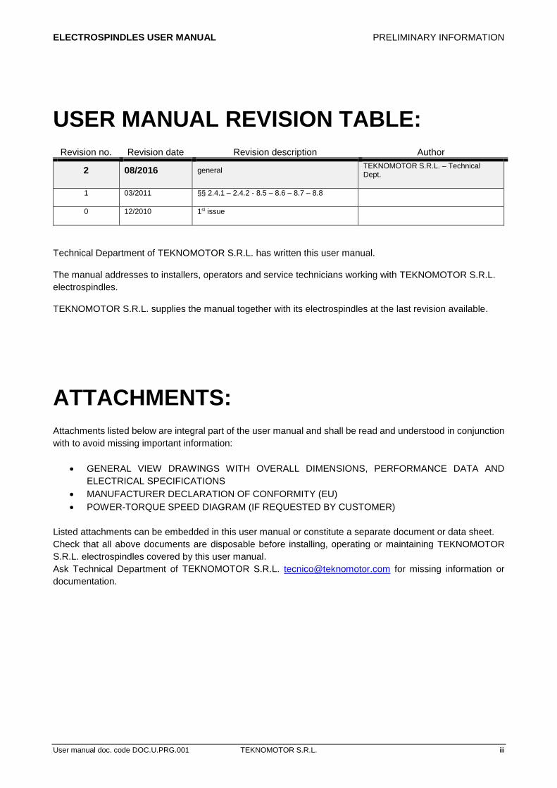
USER MANUAL REVISION TABLE:
Revision no. Revision date Revision description Author
2 08/2016 general TEKNOMOTOR S.R.L. – Technical Dept.
1 03/2011 §§ 2.4.1 – 2.4.2 - 8.5 – 8.6 – 8.7 – 8.8
0 12/2010 1st issue
Technical Department of TEKNOMOTOR S.R.L. has written this user manual.
The manual addresses to installers, operators and service technicians working with TEKNOMOTOR S.R.L.
electrospindles.
TEKNOMOTOR S.R.L. supplies the manual together with its electrospindles at the last revision available.
ATTACHMENTS:
Attachments listed below are integral part of the user manual and shall be read and understood in conjunction
with to avoid missing important information:
GENERAL VIEW DRAWINGS WITH OVERALL DIMENSIONS, PERFORMANCE DATA AND
ELECTRICAL SPECIFICATIONS
MANUFACTURER DECLARATION OF CONFORMITY (EU)
POWER-TORQUE SPEED DIAGRAM (IF REQUESTED BY CUSTOMER)
Listed attachments can be embedded in this user manual or constitute a separate document or data sheet.
Check that all above documents are disposable before installing, operating or maintaining TEKNOMOTOR
S.R.L. electrospindles covered by this user manual.
Ask Technical Department of TEKNOMOTOR S.R.L. [email protected] for missing information or
documentation.

ELECTROSPINDLES USER MANUAL PRELIMINARY INFORMATION
User manual doc. code DOC.U.PRG.001 TEKNOMOTOR S.R.L. iv

ELECTROSPINDLES USER MANUAL PRELIMINARY INFORMATION
User manual doc. code DOC.U.PRG.001 TEKNOMOTOR S.R.L. v
DISCLAIMER:
USE THE ELECTROSPINDLE ONLY FOR THE PURPOSE FOR WHICH
TEKNOMOTOR S.R.L. DESIGNED IT.
SAFE OPERATION DEPENDS ON THIS.
WARRANTY AND LIABILITY UNDER GENERAL SALES CONDITIONS OF
TEKNOMOTOR DEPEND ON THIS AND THEY WILL LAPSE IF THE
INSTRUCTIONS PROVIDED IN THIS USER MANUAL WILL NOT STRICTLY
APPLIED.
INSTALL THE ELECTROSPINDLES AS DESCRIBED IN THE FOLLOWING
SECTIONS OF THIS MANUAL AND ATTACHED TECHNICAL
DOCUMENTATION.
SAFE OPERATION DEPENDS ON THIS.
WARRANTY AND LIABILITY UNDER GENERAL SALES CONDITIONS OF
TEKNOMOTOR DEPEND ON THIS AND THEY WILL LAPSE IF THE
INSTRUCTIONS PROVIDED IN THIS USER MANUAL WILL NOT STRICTLY
APPLIED.
ELECTROSPINDLES USER MANUAL PRELIMINARY INFORMATION
User manual doc. code DOC.U.PRG.001 TEKNOMOTOR S.R.L. vi
ELECTROSPINDLES USER MANUAL INDEX
DOC.U.PRG.001 TEKNOMOTOR S.R.L. 1
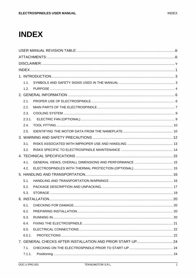
INDEX
USER MANUAL REVISION TABLE: ............................................................................................... iii
ATTACHMENTS: ............................................................................................................................ iii
DISCLAIMER: ................................................................................................................................. v
INDEX ............................................................................................................................................. 1
1. INTRODUCTION ........................................................................................................................ 3
1.1. SYMBOLS AND SAFETY SIGNS USED IN THE MANUAL ............................................................. 3
1.2. PURPOSE ......................................................................................................................................... 4
2. GENERAL INFORMATION ........................................................................................................ 6
2.1. PROPER USE OF ELECTROSPINDLE ............................................................................................ 6
2.2. MAIN PARTS OF THE ELECTROSPINDLE ..................................................................................... 7
2.3. COOLING SYSTEM .......................................................................................................................... 9
2.3.1. ELECTRIC FAN (OPTIONAL) ....................................................................................................... 9
2.4. TOOL FITTING ................................................................................................................................ 10
2.5. IDENTIFYNG THE MOTOR DATA FROM THE NAMEPLATE ....................................................... 10
3. WARNING AND SAFETY PRECAUTIONS .............................................................................. 12
3.1. RISKS ASSOCIATED WITH IMPROPER USE AND HANDLING .................................................. 13
3.2. RISKS SPECIFIC TO ELECTROSPINDLE MAINTENANCE ......................................................... 14
4. TECHNICAL SPECIFICATIONS .............................................................................................. 15
4.1. GENERAL VIEWS, OVERALL DIMENSIONS AND PERFORMANCE .......................................... 15
4.2. ELECTROSPINDLES WITH THERMAL PROTECTION (OPTIONAL) ........................................... 15
5. HANDLING AND TRANSPORTATION ..................................................................................... 16
5.1. HANDLING AND TRANSPORTATION WARNINGS ...................................................................... 16
5.2. PACKAGE DESCRIPTION AND UNPACKING............................................................................... 17
5.3. STORAGE ....................................................................................................................................... 19
6. INSTALLATION ........................................................................................................................ 20
6.1. CHECKING FOR DAMAGE ............................................................................................................. 20
6.2. PREPARING INSTALLATION ......................................................................................................... 20
6.3. RUNNING IN.................................................................................................................................... 20
6.4. FIXING THE ELECTROSPINDLE ................................................................................................... 21
6.5. ELECTRICAL CONNECTIONS ....................................................................................................... 22
6.5.1. PROTECTIONS ........................................................................................................................... 22
7. GENERAL CHECKS AFTER INSTALLATION AND PRIOR START-UP................................... 24
7.1. CHECKING ON THE ELECTROSPINDLE PRIOR TO START-UP ................................................ 24
7.1.1. Positioning ................................................................................................................................... 24

ELECTROSPINDLES USER MANUAL INDEX
DOC.U.PRG.001 TEKNOMOTOR S.R.L. 2
7.1.2. Electrical connections .................................................................................................................. 24
7.1.3. Programming the inverter ............................................................................................................ 24
7.2. CHECKING ON THE ELECROSPINDLE AT THE TIME OF FIRST START-UP ............................ 25
8. OPERATION OF THE ELECTROSPINDLE ............................................................................. 26
8.1. OPERATION LIMITATIONS ............................................................................................................ 26
8.2. INTENDED USE .............................................................................................................................. 26
8.3. SHAFT BLOCKING ......................................................................................................................... 27
8.4. CHOOSING TOOLS ........................................................................................................................ 28
8.5. TOOL MOUNTING .......................................................................................................................... 29
8.5.1. ELECTROSPINDLE WITH CONICAL SEAT FOR ER DIN 6499 ................................................ 29
8.5.1.1. MAXIMUM RUN-OUT AND VIBRATION VALUES ................................................................. 30
8.5.2. ELECTROSPINDLE WITH CILINDRICAL SHAFT ...................................................................... 31
8.6. DIFFERENT KIND OF TOOLS ........................................................................................................ 31
8.6.1. Tool with one slot ......................................................................................................................... 32
8.6.2. Tool with two slots ....................................................................................................................... 32
8.6.3. Tool with no slots ......................................................................................................................... 32
8.7. TOOL LOCKING .............................................................................................................................. 33
8.8. WARMING UP ................................................................................................................................. 34
9. MAINTENANCE ....................................................................................................................... 35
9.1. SCHEDULED MAINTENANCE AND CLEANING OF THE SPINDLE SHAFT TOOL HOUSING ... 35
9.2. OCCASIONAL MAINTENANCE ...................................................................................................... 36
10. TROUBLESHOOTING TABLE ........................................................................................... 37
11. DISPOSAL ......................................................................................................................... 38
12. MANUFACTURER DECLARATION OF CONFORMITY (UE) ............................................ 39
13. USEFULL ADRESSES ....................................................................................................... 43

ELECTROSPINDLES USER MANUAL 1. INTRODUCTION
DOC.U.PRG.001 TEKNOMOTOR S.R.L. 3
1. INTRODUCTION
1.1. SYMBOLS AND SAFETY SIGNS USED IN THE MANUAL
This manual highlights important instructions or precautions with the following symbols and safety signs (ref.
ISO 7010):
NOTE: information highlighted by symbols and safety signs is not exhaustive and the whole manual shall be read and applied
i IMPORTANT INFORMATION
GENERAL WARNING IDENTIFIED BY SUPPLEMENTARY SAFETY
INFORMATION
WARNING: SHARP ELEMENT
WARNING: FLAMMABLE MATERIAL
WARNING: ELECTRICITY
GENERAL MANDATORY ACTION IDENTIFIED BY SUPPLEMENTARY
SAFETY INFORMATION
REFER TO INSTRUCTION MANUAL BOOKLET

ELECTROSPINDLES USER MANUAL 1. INTRODUCTION
DOC.U.PRG.001 TEKNOMOTOR S.R.L. 4
DISCONNECT BEFORE CARRYING MAINTENANCE OR REPAIR
1.2. PURPOSE
This user manual contains important instructions and precautions and shall accompany the electrospindle at
all times since it is essential for the safe operation of the electrospindle and operators.
Safety precautions contained herein provide information necessary to ensure the safety of all persons exposed
to the residual risks associated with the electrospindle.
Instructions contained herein provide information necessary for the correct operation of the electrospindle.
Make sure that you read and fully understand all the documentation supplied with the electrospindle to avoid
incorrect operation of the unit and unnecessary risks of personal injury.
Keep this manual easily available in a suitable place near the machine-
Keep this manual safe, and ensure that all persons involved with the electrospindle know of it, fully understand
its contents and have access to it.
IMPORTERS AND DISTRIBUTORS SHALL ENSURE THAT USER MANUAL
ALWAYS ACCOMPANIES THE ELECTROSPINDLE AND THAT CONSUMER,
MACHINE MANUFACTURER AND OTHER END-USERS CAN EASILY FULLY
UNDERSTOOD IT.

ELECTROSPINDLES USER MANUAL 1. INTRODUCTION
DOC.U.PRG.001 TEKNOMOTOR S.R.L. 5
USE THE ELECTROSPINDLE ONLY FOR THE PURPOSE FOR WHICH
TEKNOMOTOR S.R.L. DESIGNED IT.
SAFE OPERATION DEPENDS ON THIS.
WARRANTY AND LIABILITY UNDER GENERAL SALE CONDITIONS OF
TEKNOMOTOR DEPEND ON THIS AND THEY WILL LAPSE IF THE
INSTRUCTIONS PROVIDED IN THIS USER MANUAL WILL NOT STRICTLY
APPLIED.
INSTALL THE ELECTROSPINDLES AS DESCRIBED IN THE FOLLOWING
SECTIONS OF THIS MANUAL AND ATTACHED TECHNICAL
DOCUMENTATION.
SAFE OPERATION DEPENDS ON THIS.
WARRANTY AND LIABILITY UNDER GENERAL SALE CONDITIONS OF
TEKNOMOTOR DEPEND ON THIS AND THEY WILL LAPSE IF THE
INSTRUCTIONS PROVIDED IN THIS USER MANUAL WILL NOT STRICTLY
APPLIED.

ELECTROSPINDLES USER MANUAL 2. GENERAL INFORMATION
DOC.U.PRG.001 TEKNOMOTOR S.R.L. 6
2. GENERAL INFORMATION
2.1. PROPER USE OF ELECTROSPINDLE
Electrospindles designed by TEKNOMOTOR S.R.L. shall operate as part of a machine.
MACHINE DESIGN SHALL CONSIDER THAT FRAME OF THE MACHINE
SHALL WITHSTAND THE WEIGHT OF ELECTROSPINDLE FITTED IN AND
THE STRESSES CAUSED BY TYPE OF MACHINING TO CARRY OUT.
TEKNOMOTOR S.R.L. DESIGNED ELECTROSPINDLE FOR LOW-MEDIUM
POWER MILLING AND DRILLING OF WOOD, FIBERBOARD, PLASTICS AND
ALUMINUM (SEE TO TECHNICAL DATA OF THE SPECIFIC
ELECTROSPINDLE MODEL).
USE THE ELECTROSPINDLE ONLY FOR THE PURPOSE FOR WHICH
TEKNOMOTOR S.R.L. DESIGNED IT.
SAFE OPERATION DEPENDS ON THIS.
ELECTROSPINDLES OPERATE AT S1 DUTY CYCLE UNLESS OTHERWISE
IN TECHNICAL DOCUMENTATION OF THE SPECIFIC MODEL.
CUSTOMER SHALL CARRY OPERATION OF THE ELECTROSPINDLE
ACCORDING TO SERVICE TYPE INDICATED IN TECHNICAL
DOCUMENTATION.
i
SERVICE TYPE S1 (STANDARD IEC 60034-1) MEANS OPERATION AT
CONSTANT LOAD WITH A DURATION SUFFICIENT TO ENSURE THAT THE
MOTOR REACHES THERMAL EQUILIBRIUM.
Electrospindles technical specifications vary model by model.
This user manual covers following TEKNOMOTOR S.R.L. electrospindles series:
SB TYPE: ELECTROSPINDLES FITTED WITH TWO DEEP GROOVE BEARINGS (ONE FRONT
AND ONE REAR)
Series:
COM2431xxxx – COM3140xxxx – COM4147xxxx – COM5160xxxx –
COM6067xxxx – COM7180xxxx – COMC035xxxx – COMC041xxxx –
COMC055xxxx – COMC064xxxx - COMC55Kxxxx – COMC55Mxxx –
COMC55Pxxxx – COMNC35xxxx
DB TYPE: ELECTROSPINDLES FITTED WITH A FRONT ANGULAR CONTACT BALL BEARING
SET AND A REAR SINGLE OR DOUBLE DEEP GROOVE BALL BEARING OR REAR ANGULAR
CONTACT BALL BEARING SET
Series:
COM3140xxxx – COM4147xxxx – COM5160xxxx – COM6067xxxx –
COM7180xxxx - COM8590xxxx – COMNC35xxxx

ELECTROSPINDLES USER MANUAL 2. GENERAL INFORMATION
DOC.U.PRG.001 TEKNOMOTOR S.R.L. 7
2.2. MAIN PARTS OF THE ELECTROSPINDLE
SPINDLE SHAFT
MOTOR NAME
PLATE
TERMINAL BLOCK COVER
SPINDLE NOSE
COOLING FAN
COVER

ELECTROSPINDLES USER MANUAL 2. GENERAL INFORMATION
DOC.U.PRG.001 TEKNOMOTOR S.R.L. 8
ELECTROSPINDLES USER MANUAL 2. GENERAL INFORMATION
DOC.U.PRG.001 TEKNOMOTOR S.R.L. 9
2.3. COOLING SYSTEM
Electrospindle is cooled by air forced by a fan under the rear cover.
Fan is locked on the shaft of the spindle.
Cooling efficiency therefore depends on spindle rotation speed.
Cooling is effective only in one direction of rotation for shafts with ER-clamping system.
Cooling is effective in both direction of rotation for cylindrical shafts.
i
COOLING FANS BY TEKNOMOTOR S.R.L. PROVIDE MORE EFFECTIVE
COOLING THAN TRADITIONAL AXIAL FANS.
CONTACT TEKNOMOTOR TECHNICAL OFFICE [email protected]
BEFORE USING THE ELECTROSPINDLE AT SPEED LOWER THAN THOSE
SPECIFIED ON THE ELECTROSPINDLE DATA PLATE.
MACHINE DESIGN SHALL CONSIDER THE PROPER VENTILATION OF THE
ELECTROSPINDLE TO AVOID OVERHEATING: UNLESS OTHERWISE
SPECIFIED ON TECHNICAL DOCUMENTATION, LEFT ALWAYS 100MM OF
FREE SPACE BEHIND COOLING FAN FOR MINIMUM VENTILATION AND
DON’T OBSTRUCT VENTILATION HOLES IN THE FRONT OF THE
ELECTROSPINDLE FRAME.
MACHINE DESIGN AND SAFETY DESIGN SHALL CONSIDER FIRE RISK.
2.3.1. ELECTRIC FAN (OPTIONAL)
As optional, in some version it’s available a rear mounted electric fan that cools the electrospindle.
The fan must be powered up even when the spindle is not operating.
The fan is independent of the spindle shaft.
This solution gives improved efficiency compared to shaft mounted fans.
THE FAN MUST REMAIN ON AT ALL TIMES WHEN THE MACHINE IS ACTIVE
EVEN IF THE ELECTROSPINDLE IS NOT OPERATING.
i THE VOLTAGE OF THE ELECTRIC FAN IS PRINTED ON THE
ELECTROSPINDLE NAMEPLATE.

ELECTROSPINDLES USER MANUAL 2. GENERAL INFORMATION
DOC.U.PRG.001 TEKNOMOTOR S.R.L. 10
2.4. TOOL FITTING
Various type of electrospindle shafts provided with different tool holder are available to cover most applications:
SPINDLE SHAFT WITH FLEXIBLE COLLET (ER16, ER20, ER25, ER32, ER40)
SPINDLE SHAFT WHIT CYLINDRICAL FITTING, KEY AND EXTERNALLY THREADED HEAD
SPINDLE SHAFT WHIT CYLINDRICAL FITTING, KEY AND INTERNALLY THREADED HEAD
SPINDLE SHAFT WITH SPECIAL FITTING (BLADE TYPE OR CUSTOMER DESIGN).
ALWAYS REFERE TO TOOL MANUFACTURER INSTRUCTIONS FOR
PROPER TOOL FITTING AND PERSONAL PROTECTION EQUIPMENT (PPE)
TO MANDATORY WEAR DURING INSTALLATION
2.5. IDENTIFYNG THE MOTOR DATA FROM THE NAMEPLATE
i
THE PART NUMBER (P.N. OR TYPE) AND THE SERIAL NUMBER (S.N.) ARE
PRINTED ON THE NAMEPLATE AND ARE THE ONLY MEANS RECOGNIZED
BY TEKNOMOTOR S.R.L. TO IDENTIFY THE ELECTROSPINDLE.
The nameplate shall be kept legible throughout the entire unit’s working life.
The place of the nameplate and the disposition of data in the nameplate can vary model by model.

ELECTROSPINDLES USER MANUAL 2. GENERAL INFORMATION
DOC.U.PRG.001 TEKNOMOTOR S.R.L. 11
PART NUMBER
SERIAL NUMBER
MOTOR POWER
BASE VOLTAGE Y
BASE VOLTAGE Δ
SE MODELLO
BASE FREQUENCY
BASE
MAX FREQUENCY
FAN POWER
CURRENT Δ
CURRENT Y
DUTY CYCLE
INSULATION CLASS
COSφ
INSULATION PROTECTION
BASE RPM
MAX RPM
FAN SUPPLY

ELECTROSPINDLES USER MANUAL 3. WARNING AND SAFETY PRECAUTIONS
DOC.U.PRG.001 TEKNOMOTOR S.R.L. 12
3. WARNING AND SAFETY
PRECAUTIONS
TEKNOMOTOR S.R.L. IS NOT AWARE OF HOW CONSUMER, MACHINE
MANUFACTURER AND/OR OTHER END-USER WILL INSTALL
ELECTROSPINDLE COVERED BY THIS USER MANUAL.
THEREFORE, CONSUMER, MACHINE MANUFACTURER AND/OR OTHER
END-USER SHALL PERFORM A FULL RISK ASSESSMENT SPECIFIC TO
INSTALLATION, OPERATION AND MAINTENANCE.
MACHINE DESIGN SHALL CONSIDER ACCESSIBILITY TO
ELECTROSPINDLE FOR CORRECT AND SAFE INSTALLATION AND
MAINTENANCE.
Machine and safety design shall provide adequate protection to prevent accidental contact with moving parts
during installation / operation / maintenance, considering also all other possible risks, particularly those
associated with foreign bodies, explosive atmospheres, inflammable, toxic or high temperature gasses, etc.
INSTALLATION AND MAINTENANCE SHALL BE PERFORMED IN
CONDITIONS OF MAXIMUM SAFETY, AND ONLY WITH THE MAIN POWER OF
THE MACHINE SWITCHED OFF AND THE ELECTROSPINDLE STATIONARY
(NO ROTATION).
SAFETY DESIGN SHALL CONSIDER SWITCH OFF PROCEDURE OF THE
MACHINE.
Customer shall perform a full risk analysis of the machine on which the electrospindle will be installed and
issue the conformity declaration foreseen by Appendix IIA of directive 2006/42/EC and its amendments.
TEKNOMOTOR S.R.L. DESIGNED ELECTROSPINDLE AS MACHINE
COMPONENT TO ASSEMBLE WITH OTHER COMPONENTS OR TO
INCORPORATE IN A MACHINERY.
WHEN INSTALLED INTO A MACHINERY, IT SHALL BE PLACED INTO
SERVICE ONLY IF CUSTOMER HAS DECLARED THE CONFORMITY OF THE
MACHINE WITH DIRECTIVE 2006/42/EC.
MACHINE AND SAFETY DESIGN SHALL CONSIDER THE RISK OF TOOL
DISENGAGING FROM THE ELECTROSPINDLE SHAFT DURING
OPERATION. MACHINE SHALL BE PROVIDED OF ADEQUATE

ELECTROSPINDLES USER MANUAL 3. WARNING AND SAFETY PRECAUTIONS
DOC.U.PRG.001 TEKNOMOTOR S.R.L. 13
PROTECTIONS TO AVOID ANY POSSIBLE PERSONAL INJURY CAUSED BY
ACCIDENTAL DISENGAGING.
MACHINE AND SAFETY DESIGN SHALL CONSIDER THE RISK OF
DISENGAGING OR FAILURE OF THE SPINDLE SHAFT FROM THE
ELECTROSPINDLE FRAME DURING OPERATION. MACHINE SHALL BE
PROVIDED OF ADEQUATE PROTECTIONS TO AVOID ANY POSSIBLE
PERSONAL INJURY CAUSED BY ACCIDENTAL DISENGAGING.
MACHINERY AND SAFETY DESIGN SHALL CONSIDER THE RISK OF
DISENGAGING OF THE ELECTROSPINDLE FROM THE MACHINE FRAME
DURING OPERATION. MACHINE SHALL BE PROVIDED OF ADEQUATE
PROTECTIONS TO AVOID ANY POSSIBLE PERSONAL INJURY CAUSED BY
ACCIDENTAL DISENGAGING.
MACHINE DESIGN SHALL CONSIDER THE PROPER VENTILATION OF THE
ELECTROSPINDLE TO AVOID OVERHEATING: UNLESS OTHERWISE
SPECIFIED ON TECHNICAL DOCUMENTATION, LEFT ALWAYS 100MM OF
FREE SPACE BEHIND COOLING FAN FOR MINIMUM VENTILATION AND
DON’T OBSTRUCT VENTILATION HOLES IN THE FRONT OF THE
ELECTROSPINDLE FRAME.
MACHINE DESIGN AND SAFETY DESIGN SHALL CONSIDER FIRE RISK.
3.1. RISKS ASSOCIATED WITH IMPROPER USE AND HANDLING
NEVER BYPASS, REMOVE, MODIFY OR RENDER INOPERATIVE SAFETY
DEVICES, CONTROLS OR GUARDS PROTECTING INDIVIDUAL PARTS OR
THE ELECTROSPINDLE AS A WHOLE.
On completion of servicing work for which guards, covers, or any other protections have been
removed, always make sure that they have been correctly and securely replaced and they are fully
functional before re-starting the electrospindle.
Keep all protection and safety devices in perfect working order. Also, make sure that all warning and
informative plates, labels and symbols are correctly positioned and perfectly legible.
DO NOT USE THE ELECTROSPINDLE IN EXPLOSIVE ATMOSPHERES.
MACHINE DESIGN AND SAFETY DESIGN SHALL CONSIDER THAT
TEKNOMOTOR S.R.L. ARE NOT CONFORM TO ATEX DIRECTIVES.
ELECTROSPINDLES USER MANUAL 3. WARNING AND SAFETY PRECAUTIONS
DOC.U.PRG.001 TEKNOMOTOR S.R.L. 14
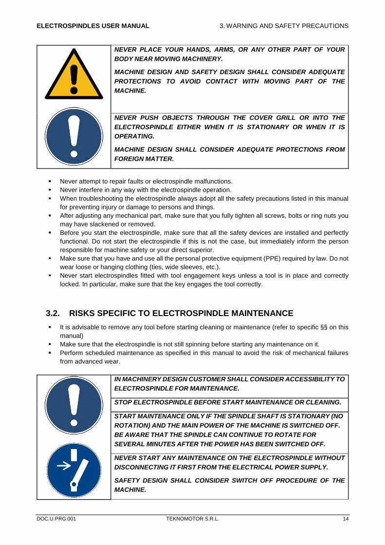
NEVER PLACE YOUR HANDS, ARMS, OR ANY OTHER PART OF YOUR
BODY NEAR MOVING MACHINERY.
MACHINE DESIGN AND SAFETY DESIGN SHALL CONSIDER ADEQUATE
PROTECTIONS TO AVOID CONTACT WITH MOVING PART OF THE
MACHINE.
NEVER PUSH OBJECTS THROUGH THE COVER GRILL OR INTO THE
ELECTROSPINDLE EITHER WHEN IT IS STATIONARY OR WHEN IT IS
OPERATING.
MACHINE DESIGN SHALL CONSIDER ADEQUATE PROTECTIONS FROM
FOREIGN MATTER.
Never attempt to repair faults or electrospindle malfunctions.
Never interfere in any way with the electrospindle operation.
When troubleshooting the electrospindle always adopt all the safety precautions listed in this manual
for preventing injury or damage to persons and things.
After adjusting any mechanical part, make sure that you fully tighten all screws, bolts or ring nuts you
may have slackened or removed.
Before you start the electrospindle, make sure that all the safety devices are installed and perfectly
functional. Do not start the electrospindle if this is not the case, but immediately inform the person
responsible for machine safety or your direct superior.
Make sure that you have and use all the personal protective equipment (PPE) required by law. Do not
wear loose or hanging clothing (ties, wide sleeves, etc.).
Never start electrospindles fitted with tool engagement keys unless a tool is in place and correctly
locked. In particular, make sure that the key engages the tool correctly.
3.2. RISKS SPECIFIC TO ELECTROSPINDLE MAINTENANCE
It is advisable to remove any tool before starting cleaning or maintenance (refer to specific §§ on this
manual)
Make sure that the electrospindle is not still spinning before starting any maintenance on it.
Perform scheduled maintenance as specified in this manual to avoid the risk of mechanical failures
from advanced wear.
IN MACHINERY DESIGN CUSTOMER SHALL CONSIDER ACCESSIBILITY TO
ELECTROSPINDLE FOR MAINTENANCE.
STOP ELECTROSPINDLE BEFORE START MAINTENANCE OR CLEANING.
START MAINTENANCE ONLY IF THE SPINDLE SHAFT IS STATIONARY (NO
ROTATION) AND THE MAIN POWER OF THE MACHINE IS SWITCHED OFF.
BE AWARE THAT THE SPINDLE CAN CONTINUE TO ROTATE FOR
SEVERAL MINUTES AFTER THE POWER HAS BEEN SWITCHED OFF.
NEVER START ANY MAINTENANCE ON THE ELECTROSPINDLE WITHOUT
DISCONNECTING IT FIRST FROM THE ELECTRICAL POWER SUPPLY.
SAFETY DESIGN SHALL CONSIDER SWITCH OFF PROCEDURE OF THE
MACHINE.

ELECTROSPINDLES USER MANUAL 4. TECHNICAL SPECIFICATIONS
DOC.U.PRG.001 TEKNOMOTOR S.R.L. 15
4. TECHNICAL SPECIFICATIONS
4.1. GENERAL VIEWS, OVERALL DIMENSIONS AND PERFORMANCE
See technical documentation supplied with electrospindle.
If any information is not available, please contact TEKNOMOTOR S.R.L. Technical Department
4.2. ELECTROSPINDLES WITH THERMAL PROTECTION (OPTIONAL)
Electrospindles can get heated due to overloading, high ambient temperature, variations in power quality, etc.
Thermal overload can result in stator overheating, faulty operation and in some extreme cases even fire.
MACHINE DESIGN SHALL CONSIDER THE PROPER VENTILATION OF THE
ELECTROSPINDLE TO AVOID OVERHEATING: UNLESS OTHERWISE
SPECIFIED ON TECHNICAL DOCUMENTATION, LEFT ALWAYS 100MM OF
FREE SPACE BEHIND COOLING FAN FOR MINIMUM VENTILATION AND
DON’T OBSTRUCT VENTILATION HOLES IN THE FRONT OF THE
ELECTROSPINDLE FRAME.
MACHINE DESIGN AND SAFETY DESIGN SHALL CONSIDER FIRE RISK.
NOTE:THERMAL PROTECTION IS ONLY A SENSOR WHICH CAN PROVIDE
A SIGNAL, IF CORRECTLY CONNECTED TO OTHER ADEQUATE DEVICES,
WHEN A CERTAIN TEMPERATURE IS REACHED.
PTC THERMISTOR:
A PTC thermistor is inserted in the stator windings to monitor temperature.
Electrical resistance of the thermistor increases rapidly as it reaches trip temperature (100°C / 130°C,
depending on the model).
The signal of the thermistor can be routed to a control device to stop the machine in order to protect the
electrospindle from the effects of overheating.
BIMETALLIC THERMAL PROTECTION:
A bimetallic thermal protection is inserted in the stator windings.
The electrical contacts are NC (NORMALLY CLOSED).
When the bimetallic disc reaches its trip temperature,the contact will automatically OPEN.
The contact will automatically reset CLOSED once the electrospindle cools to a safe predefined level.

ELECTROSPINDLES USER MANUAL 5. HANDLING AND TRANSPORTATION
DOC.U.PRG.001 TEKNOMOTOR S.R.L. 16
5. HANDLING AND TRANSPORTATION
5.1. HANDLING AND TRANSPORTATION WARNINGS
Respect safety regulations for handling, lifting and transportation of heavy loads.
Handling and lifting of electrospindles can cause injury to involved personnel.
Always use suitable and safe handling and lifting procedures and equipment.
Always use great care in lifting and handling electrospindles and their components.
Avoid impacts, which can damage the body or the shaft or the bearings of the electrospindle.
Do not drill electrospindle to fit any hosting device.
When handling, lifting and transporting packaged items, respect instructions given by handling and
storage symbols stenciled on the packages as per following examples (ref. to ISO 780):
Importers, distributors, consumer, machine manufacturer or other end-user are in turn responsible for
the design of safe handling, lifting and transportation of the electrospindles under their responsibility.

ELECTROSPINDLES USER MANUAL 5. HANDLING AND TRANSPORTATION
DOC.U.PRG.001 TEKNOMOTOR S.R.L. 17
IT IS THE RESPONSIBILITY OF THE CUSTOMER TO ENSURE THAT USED
LIFTING EQUIPMENT IS SUITABLE FOR THE PURPOSE.
NEVER LIFT THE ELECTROSPINDLE BY ITS FAN COVER. THIS CAN
BREAK, DAMAGING THE ELECTROSPINDLE AND POSSIBLY CAUSING
PERSONAL INJURY.
NEVER DRILL PARTS OF ELECTROSPINDLE TO ATTACH HOSTING
DEVICES TO HANDLE ELECTROSPINDLE.
i ELECTROSPINDLE MODELS OF SERIES 7180XXXX AND 8590XXXX ARE
PROVIDED WITH T-SLOT UNI 5131 / DIN 508.
5.2. PACKAGE DESCRIPTION AND UNPACKING
The product is shipped protected by cardboard inserts, VCI plastic wrapping or barrier bag and expanded
polyurethane foam as necessary and packed in a wooden case or in a cardboard box.
Cardboard box can be wrapped to a wood or plastic (euro-)pallet.
If phytosanitary requirements shall be enforced, the wood conforms to the requirements of IPPC ISPM 15
regulation and marked as per following examples:

ELECTROSPINDLES USER MANUAL 5. HANDLING AND TRANSPORTATION
DOC.U.PRG.001 TEKNOMOTOR S.R.L. 18
Prior to opening the packing, verify that adhesive seals are still intact. If note report this to TEKNOMOTOR S.R.L. [email protected] to manage consequent actions. If the electrospindle is delivered in a wooden case, cut plastic wire wrappings, remove seals and insert a screwdriver under the fasteners and use it as a lever taking care not to damage the case. Once opened the case, remove internal protections (e.g. barrier bag, expanded polyurethane foam,…) taking care not to damage the content. If the electrospindle is packed in a cardboard box, cut plastic wire wrappings, remove seals and internal protections taking care not to damage the content.
ELECTROSPINDLES USER MANUAL 5. HANDLING AND TRANSPORTATION
DOC.U.PRG.001 TEKNOMOTOR S.R.L. 19
5.3. STORAGE
Unpack electrospindle and store it in a close warehouse protecting it from direct sunlight, rain, damp, dust,
aggressive atmospheres, etc.
Storage environmental conditions shall be:
STORAGE TEMPERATURE: from -5°C to +40°C
RELATIVE HUMIDITY (RH): from 5% to 55%
i
MAXIMUM STORAGE TIME IS TWELVE (12) MONTHS.
CONTACT TEKNOMOTOR TECHNICAL OFFICE [email protected]
FOR FURTHER INSTRUCTIONS ON LONGER STORAGE TIME.
Monitor storage conditions (i.e.: protection and environment) regularly.
Manually rotate the shaft approximately once a month in order to maintain grease distribution on bearing races.

ELECTROSPINDLES USER MANUAL 6. INSTALLATION
DOC.U.PRG.001 TEKNOMOTOR S.R.L. 20
6. INSTALLATION
6.1. CHECKING FOR DAMAGE
Before to start installation, check:
That no part of electrospindle has been damaged during handling and/or transportation,
That there is no sign of damp or water inside the connection terminal board,
That the terminal board and its cover are not damaged in any way.
IF THE ELECTROSPINDLE IS DAMAGED REPORT THIS TO TEKNOMOTOR
S.R.L. [email protected] TO MANAGE CONSEQUENT ACTIONS. DO NOT ATTEMPT TO REPAIR ELECTROSPINDLE WITHOUT
AUTHORIZATION BY TEKNOMOTOR S.R.L.
6.2. PREPARING INSTALLATION
The machinery manufacturer or other end-user is the sole responsible of all work in preparation of installation
of the electrospindle (e.g. preparation of electrical power supplies, compressed air etc.).
Make sure that the electrical power line to the electrospindle is of adequate section and power.
Qualified electricians must only do connection of the unit to the power supply.
The machinery manufacturer or other end-user is the sole responsible for power supply system and connectors
to the electrospindle.
ATTENTION: ELECTROSPINDLE SHALL BE CORRECTLY CONNECTED TO
EARTH.
THE EARTH CONNECTION MUST COMPLY WITH APPLICABLE
REGULATIONS AND MUST BE DULY CHECKED AND TESTED BY
QUALIFIED TECHNICIANS.
6.3. RUNNING IN
Electrospindle is run in in the factory prior to shipment to ensure correct distribution of the long-life grease in
the bearing races.
The running in cycle includes comprehensive testing of all electrospindle electrical and mechanical parts.
ELECTROSPINDLES USER MANUAL 6. INSTALLATION
DOC.U.PRG.001 TEKNOMOTOR S.R.L. 21
Before operation, machine manufacturercon or other end-user shall also run-in the electrospindle according to
the following instructions:
STEP 1
run the electrospindle at a speed of 3000 rpm for 2 minutes
STEP 2
increase the speed of 3000 rpm every 2 minutes up to the maximum speed written on the nameplate of electrospindle
During running in, check temperature of electrospindle nose and if temperature exceeds +50°C stop the
electrospindle.
Restart the run in from the last speed applied when the electrospindle temperature reaches the ambient
temperature.
6.4. FIXING THE ELECTROSPINDLE
The electrospindle shall be fixed to the machine by means of bolts.
i EXCESSIVE BOLT PENETRATION ON THE ELECTROSPINDLE FRAME CAN
CAUSE DEFORMATION OF THE ELECTROSPINDLE BODY, AND
MECHANICAL OR ELECTRICAL DAMAGE THAT CAN LEAD TO SPINDLE
MALFUNCTIONING OR FAILURE.
i
FIXING BOLTS SHALL BE TIGHTENED WITH A TORQUE WRENCH.
IT IS VERY IMPORTANT TO RESPECT THE TIGHTENING TORQUE
SPECIFICATION, ESPECIALLY WHEN INSTALLING ELECTROSPINDLE ON
WHICH ONLY A LIMITED LENGTH OF BOLT CAN BE SCREWED INTO THE
FIXING HOLES.
MACHINE DESIGN SHALL DETERMINE NECESSARY TIGHTENING TORQUE.
EFFECTIVE TIGHTENING TORQUE CAN VARY SIGNIFICANTLY UNDER THE
EFFECT OF FRICTION, THE PRESENCE OF GREASE, AND THE SPEED AT
WHICH TIGHTENING IS DONE.
WHILE FIXING THE UNIT IN PLACE, TAKE CARE NOT TO BLOCK OFF
THE COOLING FAN GRILL OR OTHERWISE IMPEDE THE FLOW OF
COOLING AIR.
MACHINE DESIGN SHALL CONSIDER THE PROPER VENTILATION OF THE
ELECTROSPINDLE TO AVOID OVERHEATING: UNLESS OTHERWISE
SPECIFIED ON TECHNICAL DOCUMENTATION, LEFT ALWAYS 100MM OF
FREE SPACE BEHIND COOLING FAN FOR MINIMUM VENTILATION AND
DON’T OBSTRUCT VENTILATION HOLES IN THE FRONT OF THE
ELECTROSPINDLE FRAME.

ELECTROSPINDLES USER MANUAL 6. INSTALLATION
DOC.U.PRG.001 TEKNOMOTOR S.R.L. 22
6.5. ELECTRICAL CONNECTIONS
REFER TO DATA SHEET AND INVERTER CONFIGURATION.
ATTENTION: ALWAYS USE POWER CABLE OF ADEQUATE CROSS
SECTION FOR THE RATED CURRENT OF THE ELECTRIC MOTOR.
NEVER FIT OR REMOVE CONNECTORS WITH THE ELECTROSPINDLE POWERED ON.
6.5.1. PROTECTIONS
DO NOT OPERATE AT SPEED HIGHER THAN SPECIFIED IN TECHNICAL
DOCUMENTATION OF THE ELECTROSPINDLE TO AVOID DAMAGE,
FAILURE AND/OR DISENGAGING.
MACHINE SHALL BE PROVIDED OF ADEQUATE PROTECTIONS TO AVOID
ANY POSSIBLE PERSONAL INJURY CAUSED BY ACCIDENTAL
DISENGAGING.
DOT NOT OPERATE AT SPEED HIGHER THAN SPECIFIED IN TECHNICAL
DOCUMENTATION OF THE TOOL FITTED ON THE ELECTROSPINDLE TO
AVOID DAMAGE, FAILURE AND/OR DISENGAGING.
MACHINE SHALL BE PROVIDED OF ADEQUATE PROTECTIONS TO AVOID
ANY POSSIBLE PERSONAL INJURY CAUSED BY ACCIDENTAL
DISENGAGING.
For the safety of people and/or objects, machine manufacturer or other end-user shall provide protections to
avoid direct contact with live parts and indirect contact with parts which are not live under normal conditions
but which may become so in the event of a fault.
If the safety of the machine depends on the rotation direction of the motor shaft, it is recommended to take
precautions to avoid an inversion of the phases; in this case, the direction of rotation must be indicated with a
visible label.
All electrical circuits must be protected against damage resulting from faults or malfunctions due to: short-
circuit overloads, overload current, interruption or reduction of the supply voltage, excessive speed of
machinery components, overheating in case of a high number of on-load starts.

ELECTROSPINDLES USER MANUAL 6. INSTALLATION
DOC.U.PRG.001 TEKNOMOTOR S.R.L. 23
REFERE TO INVERTER MANUAL TO DETERMINE PROTECTIONS OF
SHORT-CIRCUIT OVERCURRENTS AND OVERLOAD CURRENTS.

ELECTROSPINDLES USER MANUAL 7. GENERAL CHECKS AFTER INSTALLATION AND PRIOR THE STARTUP
DOC.U.PRG.001 TEKNOMOTOR S.R.L. 24
7. GENERAL CHECKS AFTER
INSTALLATION AND PRIOR START-UP
7.1. CHECKING ON THE ELECTROSPINDLE PRIOR TO START-UP
7.1.1. Positioning
Make sure that there is sufficient space behind the electrospindle cooling grill, at least 100mm.
7.1.2. Electrical connections
Make sure that the electrospindle earthing cable or earthing terminal is connected to the machine
earth.
Make sure that the signal from the motor’s PTC thermistor or bimetallic protection, if optioned, is
suitably processed and connected in series with the machine’s stop circuit.
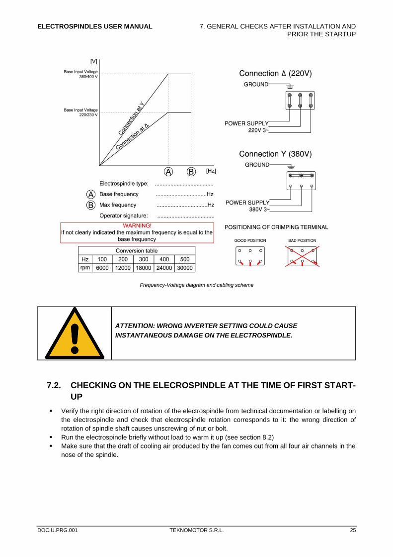
7.1.3. Programming the inverter
Make sure that the maximum supply voltage value corresponds to that specified on the electrospindle
nameplate.
Make sure that the frequency value at maximum voltage corresponds to that specified on the
electrospindle nameplate.
Make sure that the maximum frequency value corresponds to that specified on the electrospindle
nameplate.
The inverter shall be programmed with the ratio V/f constant.
Contact TEKNOMOTOR S.R.L. Technical Department [email protected] to check other
inverter parameters.
ELECTROSPINDLES USER MANUAL 7. GENERAL CHECKS AFTER INSTALLATION AND PRIOR THE STARTUP
DOC.U.PRG.001 TEKNOMOTOR S.R.L. 25
Frequency-Voltage diagram and cabling scheme
ATTENTION: WRONG INVERTER SETTING COULD CAUSE
INSTANTANEOUS DAMAGE ON THE ELECTROSPINDLE.
7.2. CHECKING ON THE ELECROSPINDLE AT THE TIME OF FIRST START-
UP
Verify the right direction of rotation of the electrospindle from technical documentation or labelling on
the electrospindle and check that electrospindle rotation corresponds to it: the wrong direction of
rotation of spindle shaft causes unscrewing of nut or bolt.
Run the electrospindle briefly without load to warm it up (see section 8.2)
Make sure that the draft of cooling air produced by the fan comes out from all four air channels in the
nose of the spindle.
ELECTROSPINDLES USER MANUAL 8. OPERATION OF THE ELECTROSPINDLE
DOC.U.PRG.001 TEKNOMOTOR S.R.L. 26
8. OPERATION OF THE
ELECTROSPINDLE
8.1. OPERATION LIMITATIONS
Unless otherwise specified in technical documentation, TEKNOMOTOR S.R.L. designed electrospindle to
operate within the following limitation:
Altitude not above 1000 m above sea level
Maximum ambient air temperature not above 40°C
Minimum ambient air temperature not below 10°C
Electrospindle cannot work in foggy environments or with coolant jet directly in the spindle nose.
Specific pneumatic sealed electrospindle are available for such environments (contact TEKNOMOTOR S.R.L.
Technical Department [email protected] for more information).
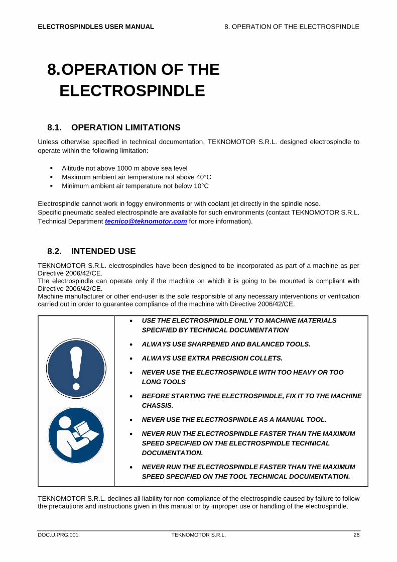
8.2. INTENDED USE
TEKNOMOTOR S.R.L. electrospindles have been designed to be incorporated as part of a machine as per Directive 2006/42/CE. The electrospindle can operate only if the machine on which it is going to be mounted is compliant with Directive 2006/42/CE. Machine manufacturer or other end-user is the sole responsible of any necessary interventions or verification carried out in order to guarantee compliance of the machine with Directive 2006/42/CE.
USE THE ELECTROSPINDLE ONLY TO MACHINE MATERIALS
SPECIFIED BY TECHNICAL DOCUMENTATION
ALWAYS USE SHARPENED AND BALANCED TOOLS.
ALWAYS USE EXTRA PRECISION COLLETS.
NEVER USE THE ELECTROSPINDLE WITH TOO HEAVY OR TOO
LONG TOOLS
BEFORE STARTING THE ELECTROSPINDLE, FIX IT TO THE MACHINE
CHASSIS.
NEVER USE THE ELECTROSPINDLE AS A MANUAL TOOL.
NEVER RUN THE ELECTROSPINDLE FASTER THAN THE MAXIMUM
SPEED SPECIFIED ON THE ELECTROSPINDLE TECHNICAL
DOCUMENTATION.
NEVER RUN THE ELECTROSPINDLE FASTER THAN THE MAXIMUM
SPEED SPECIFIED ON THE TOOL TECHNICAL DOCUMENTATION.
TEKNOMOTOR S.R.L. declines all liability for non-compliance of the electrospindle caused by failure to follow the precautions and instructions given in this manual or by improper use or handling of the electrospindle.

ELECTROSPINDLES USER MANUAL 8. OPERATION OF THE ELECTROSPINDLE
DOC.U.PRG.001 TEKNOMOTOR S.R.L. 27
In case of any doubt regarding the correct use of electrospindle, do not hesitate to contact TEKNOMOTOR S.R.L. Technical Department [email protected].
8.3. SHAFT BLOCKING
SAFETY DESIGN SHALL CONSIDER SWITCH OFF PROCEDURE OF THE
MACHINE.
THE OPERATOR SHALL FIT THE TOOL ON THE HOLDER ON THE SHAFT
ONLY IF THE MAIN POWER OF THE MACHINE IS SWITCHED OFF AND THE
SPINDLE SHAFT IS STATIONARY (NO ROTATION).
Switch off the machine.
Wait until the spindle shaft is stationary.
Block the shaft by one of the following:
- SHAFT BLOCKING BY REAR HEXAGONAL HOLE ON THE SPINDLE SHAFT.
- SHAFT BLOCKING BY FRONT HEXAGONAL HOLE ON THE SPINDLE SHAFT.
- SHAFT BLOCKING BY FRONT FLAT ON THE SPINDLE SHAFT.
- SHAFT BLOCKING BY SHAFT BLOCKING PIN (C7180xxxx – C8590xxxx).
Shaft blocking by rear hexagonal hole on the spindle shaft:
Insert the proper allen spanner into the hexagonal hole in the rear part of the shaft and keep it steady.
Shaft blocking by front hexagonal hole on the spindle shaft:
Insert the proper allen spanner into the hexagonal hole in the front part of the shaft and keep it steady.
Shaft blocking by front flat on the spindle shaft:
Insert the proper wrench into the flat and keep it steady.
Shaft blocking by shaft blocking pin: (C7180xxxx – C8590xxxx).
A spring-loaded pin is positioned in the motor near the spindle nose. Gently press the pin against the shaft and
in the meantime manually rotate the shaft until the pin finds the proper dropping down and blocking the shaft.
When releasing, the blocking pin shall return to its original position by action of the internal spring.
BEFORE RE-START THE MOTOR, BE SURE THAT THE BLOCKING PIN
RETURNS TO ITS ORIGINAL POSITION AND THE SHAFT IS FREE TO
ROTATE.
ELECTROSPINDLES USER MANUAL 8. OPERATION OF THE ELECTROSPINDLE
DOC.U.PRG.001 TEKNOMOTOR S.R.L. 28
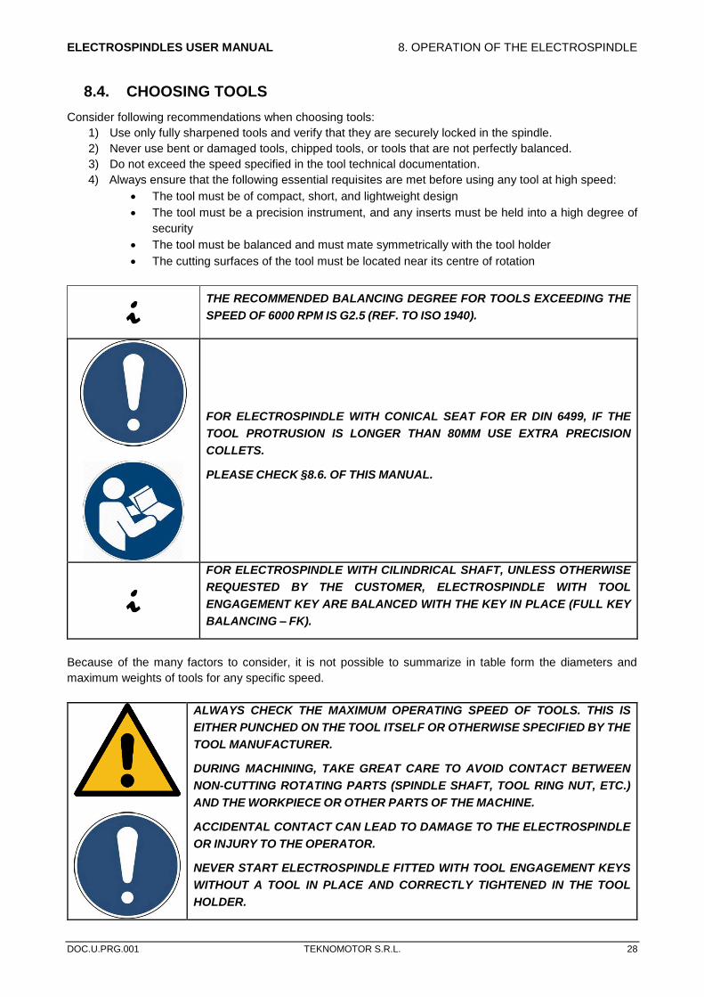
8.4. CHOOSING TOOLS
Consider following recommendations when choosing tools:
1) Use only fully sharpened tools and verify that they are securely locked in the spindle.
2) Never use bent or damaged tools, chipped tools, or tools that are not perfectly balanced.
3) Do not exceed the speed specified in the tool technical documentation.
4) Always ensure that the following essential requisites are met before using any tool at high speed:
The tool must be of compact, short, and lightweight design
The tool must be a precision instrument, and any inserts must be held into a high degree of
security
The tool must be balanced and must mate symmetrically with the tool holder
The cutting surfaces of the tool must be located near its centre of rotation
i THE RECOMMENDED BALANCING DEGREE FOR TOOLS EXCEEDING THE
SPEED OF 6000 RPM IS G2.5 (REF. TO ISO 1940).
FOR ELECTROSPINDLE WITH CONICAL SEAT FOR ER DIN 6499, IF THE
TOOL PROTRUSION IS LONGER THAN 80MM USE EXTRA PRECISION
COLLETS.
PLEASE CHECK §8.6. OF THIS MANUAL.
i FOR ELECTROSPINDLE WITH CILINDRICAL SHAFT, UNLESS OTHERWISE
REQUESTED BY THE CUSTOMER, ELECTROSPINDLE WITH TOOL
ENGAGEMENT KEY ARE BALANCED WITH THE KEY IN PLACE (FULL KEY
BALANCING – FK).
Because of the many factors to consider, it is not possible to summarize in table form the diameters and
maximum weights of tools for any specific speed.
ALWAYS CHECK THE MAXIMUM OPERATING SPEED OF TOOLS. THIS IS
EITHER PUNCHED ON THE TOOL ITSELF OR OTHERWISE SPECIFIED BY THE
TOOL MANUFACTURER.
DURING MACHINING, TAKE GREAT CARE TO AVOID CONTACT BETWEEN
NON-CUTTING ROTATING PARTS (SPINDLE SHAFT, TOOL RING NUT, ETC.)
AND THE WORKPIECE OR OTHER PARTS OF THE MACHINE.
ACCIDENTAL CONTACT CAN LEAD TO DAMAGE TO THE ELECTROSPINDLE
OR INJURY TO THE OPERATOR.
NEVER START ELECTROSPINDLE FITTED WITH TOOL ENGAGEMENT KEYS
WITHOUT A TOOL IN PLACE AND CORRECTLY TIGHTENED IN THE TOOL
HOLDER.

ELECTROSPINDLES USER MANUAL 8. OPERATION OF THE ELECTROSPINDLE
DOC.U.PRG.001 TEKNOMOTOR S.R.L. 29
8.5. TOOL MOUNTING
8.5.1. ELECTROSPINDLE WITH CONICAL SEAT FOR ER DIN 6499
The tool mounting is a careful operation because it define the electrospindle life.
i EXCESSIVE TOOL RUN-OUT CAUSES PREMATURE WEAR OF BEARINGS.
Before fixing the tool on the electrospindle:
Carefully blow with compressed air the inside taper, the nut, the collet and the tool.
Clean them with mix thinner-oil (92%+8%) to remove the processing residual; if it is necessary use
soft paper.
Fix the collet on the nut and check that it could turn freely.
Insert them into the inside taper of the electrospindle and screw the nut by hand.
Insert the tool and check that it could axially move freely.
Position the tool in order that the collet clamps the tool on the total length of contact.
Screw the nut with the advised torque using the specific wrench.
Check the run out of the tool or if it is not possible check the vibration level of the motor.

ELECTROSPINDLES USER MANUAL 8. OPERATION OF THE ELECTROSPINDLE
DOC.U.PRG.001 TEKNOMOTOR S.R.L. 30
8.5.1.1. MAXIMUM RUN-OUT AND VIBRATION VALUES
Check that the tool is aligned with the shaft.
Use a dial gauge with high resolution (0.001 mm) to measure the tool run-out.
The maximum allowed run-out is 0.02mm @ 100mm far from the collet (L1).
If it is not possible to measure the tool run-out because of the tool design, use a vibrometer to check the
vibration level of the motor.
The maximum vibration value should not exceed 2.0-2.5mm/s.
The concentricity values according to DIN 6388 are shown on the following table:
Concentricity collets values
Ø B mm
L1 mm
DIN6388 mm
Extra precise mm
da a
1.0 1.6 6.0 0.015 0.005
1.6 3.0 10.0 0.015 0.005
3.0 6.0 16.0 0.015 0.005
6.0 10.0 25.0 0.015 0.005
10.0 18.0 40.0 0.020 0.005
18.0 26.0 50.0 0.020 0.005
The run-out values of 3 type of collets on the market are shown on the following table:
MEASURED RUN OUT OF GRINDED PIN Ø20mm WITH ER32 COLLET
Distance between collet and
measurement point L1 Collet low quality Collet medium quality
Collet high quality (extra precise)
90mm 120µm 70µm 20µm
In the same way the vibration values of the motor with 3 different types of collet on the market are shown on the following table:
MEASURED VIBRATION VALUES OF THE MOTOR WITH ER32 COLLET AND GRINDED PIN Ø20mm 360g
rpm Collet low quality Collet medium quality Collet high quality
(extra precise)
12000 3.0 mm/s (front) 3.2 mm/s (rear)
2.0 mm/s (front) 1.1 mm/s (rear)
0.7 mm/s (front ) 0.3 mm/s (rear)
18000 4.2 mm/s (front) 4.6 mm/s (rear)
3.3 mm/s (front) 2.0 mm/s (rear)
1.3 mm/s (front) 0.5mm/s (rear)
The experimental results underline that a heavy tool as a milling tool (Ø 16 mm used on the door machine)
needs an extra precise collet.

ELECTROSPINDLES USER MANUAL 8. OPERATION OF THE ELECTROSPINDLE
DOC.U.PRG.001 TEKNOMOTOR S.R.L. 31
Excessive tool run-out causes a premature wear of the rear bearings as clearly shown on the above table.
i
USE EXTRA PRECISE COLLETS TO GUARANTEE A LONG LIFE OF YOUR
ELECTROSPINDLE.
8.5.2. ELECTROSPINDLE WITH CILINDRICAL SHAFT
The tool mounting is a careful operation because it define the electrospindle life.
i EXCESSIVE TOOL RUN-OUT CAUSES PREMATURE WEAR OF BEARINGS.
THE MAXIMUM VIBRATION LEVEL SHOULD NOT EXCEED 2.0 -2.5 MM/S
Before fixing the tool on the electrospindle:
Carefully blow with compressed air the shaft, the nut and the tool.
Clean them with mix thinner-oil (92%+8%) to remove the processing residual if it is necessary
use soft paper.
Screw the nut or the screw with the advised torque using the specific wrench.
Check the vibration level of the motor.
CHECK THAT THE TYPE OF BALANCING OF THE MOTOR MATCH WITH THE
BALANCING OF THE TOOL:
- FOR MOTOR BALANCED WITH FULL KEY (FK) USE A TOOL WITH TWO
SLOTS.
- FOR MOTOR BALANCED WITH HALF KEY (HK) USE TOOL WITH ONE
SLOT.
A WRONG COUPLING OF MOTOR AND TOOL BALANCING CAN CAUSE A
PREMATURE BEARING FAILURE.
A WRONG COUPLING OF ELECTROSPINDLE AND TOOL BALANCING CAN
PROVOKE SERIOUS INJURIES OR DEATH.
8.6. DIFFERENT KIND OF TOOLS
It is fundamental to define the correct type of balancing to avoid any excessive vibration when the motor is
coupled with the tool.
A wrong match between tool and motor shaft causes vibrations, which can compromise the finishing grade of
the part as well as considerably reduce the motor life.

ELECTROSPINDLES USER MANUAL 8. OPERATION OF THE ELECTROSPINDLE
DOC.U.PRG.001 TEKNOMOTOR S.R.L. 32
i
DIFFERENT KIND OF TOOLS REQUIRES DIFFERENT KIND OF SHAFT
BALANCING.
8.6.1. Tool with one slot
This kind of tool requires a half key balancing (HK) shaft. In this case there are two asymmetrical and
unbalanced rotating parts (motor shaft and tool) which will be matched together. If correctly designed the
matching will define a balanced system.
Some important point to be considered are:
- Equal length between tool (or tool + spacer) and
keyway.
- Minimum gap between shaft keyway and the tool
(gap=A-B< 0.5mm)
- Same density of tool body and shaft key [kg/dm3].
- Respect of the coupling tolerances (Øtool-Øshaft < 0.02mm)
8.6.2. Tool with two slots
This kind of tool requires a full key balancing (FK) shaft or a shaft with two symmetrical keyways (suggested
option). In this case there are two symmetrical and balanced rotating parts (motor
shaft and tool) which will be matched together. The correct matching is
independent from the length of the keyways/tool. It is independent from the gap
and from the density of the tool body
The only important point to be considered is:
- Respect of the coupling tolerances (Øtool-Øshaft < 0.02mm)
8.6.3. Tool with no slots
This kind of tool requires a plain shaft. In this case the torque is transmitted by friction. The correct matching
is independent from the length of the shaft/tool. It is independent from the density of the tool body
The only important point to be considered is:
- Respect of the coupling tolerances (Øtool-Øshaft < 0.02mm).
- Respect of the versus of the locking thread nut. If, looking from the front, the
motor rotate clockwise the thread should be counterclockwise. If the motor rotate
counterclockwise the thread should be clockwise.
i
TEKNOMOTOR S.R.L. DOES NOT ASSUME ANY RESPONSIBILITY FOR THE
GIVEN SUGGESTIONS ABOUT THE TOOL CHOOSING, COUPLING AND
LOCKING.
ANY RESPONSIBILITY IS OF THE DESIGNER AND MANUFACTURER OF
THE MACHINE.

ELECTROSPINDLES USER MANUAL 8. OPERATION OF THE ELECTROSPINDLE
DOC.U.PRG.001 TEKNOMOTOR S.R.L. 33
TOOLS ROTATING AT HIGH SPEED ARE VERY DANGEROUS AS THEY CAN
BE EJECTED FROM THE MACHINE AND SERIOUSLY INJURY OR EVEN
KILL PEOPLE.
EVEN OBJECTS, CHIPS AND OTHER POTENTIALLY DANGEROUS PARTS
CAN BE EJECTED.
MACHINE DESIGN SHALL CONSIDER ALL MEASURES NECESSARY TO
PROTECT PEOPLE FROM ANY RISK ASSOCIATED TO HIGH SPEED
ROTATING TOOLS EVEN IN CASE OF AN ELECTROSPINDLE FAILURE.
If you have any doubt o you need any clarification do not hesitate to contact TEKNOMOTOR S.R.L. Technical
Department [email protected].
8.7. TOOL LOCKING
Once the shaft is blocked, it is possible to mount/dismount the tool.
TOOL EDGES MAY BE VERY SHARP AND CAN CAUSE SERIOUS INJURIES.
ALWAYS REFERE TO TOOL MANUFACTURER INSTRUCTIONS FOR
PROPER TOOL FITTING AND PERSONAL PROTECTION EQUIPMENT (PPE)
TO MANDATORY WEAR DURING INSTALLATION.
The tool can be locked by ring nuts or by screws.
Move can be transmitted from the spindle shaft to the tool either by friction (close contact) or by a key.
MAKE SURE THAT THE RING NUTS AND THE TOOL ARE TIGHT BEFORE RE-
STARTING THE ELECTROSPINDLE.
ON VERSIONS FITTED WITH A TOOL ENGAGEMENT KEY, NEVER START
THE ELECTROSPINDLE WITHOUT A TOOL IN PLACE AND CORRECTLY
TIGHTENED.
ON VERSIONS FITTED WITH A SHAFT LOCKING PIN, MAKE SURE THAT THE
PIN IS FULLY DISENGAGED FROM THE SHAFT BEFORE RE-STARTING THE
ELECTRO SPINDLE. ALSO ALWAYS.
MAKE SURE THAT THE ELECTRO SPINDLE IS STATIONARY AND NOT
POWERED ON BEFORE TURNING THE SHAFT AND ENGAGING THE PIN.

ELECTROSPINDLES USER MANUAL 8. OPERATION OF THE ELECTROSPINDLE
DOC.U.PRG.001 TEKNOMOTOR S.R.L. 34
8.8. WARMING UP
Every day, when the electrospindle is started up for the first time, leave it warm up slowly without load.
This ensures that the bearings reach their running temperature gradually, and that the bearing races expand
evenly.
To warm up electrospindle, operate it without load for five (5) at 50% of maximum speed specified on technical
documentation.
Warm the electrospindle up before machining whenever the machine has been left idle long enough for it to
cool down to ambient temperature.
ELECTROSPINDLES USER MANUAL 9. MAINTENANCE
DOC.U.PRG.001 TEKNOMOTOR S.R.L. 35
9. MAINTENANCE
Read this section carefully before attempting any maintenance on the electrospindle.
This section contains information that is important for the safety of maintenance personnel and for the reliability
of maintenance work itself.
All applicable safety precautions shall be taken whenever maintenance work is done on the electrospindle.
In particular:
Maintenance and/or lubrication shall be performed only by qualified, expert personnel, with the
authorization of factory management, in compliance with applicable safety directives and standards,
and with the use of suitable tools and instruments.
When performing maintenance, always wear suitable clothing such as tight fitting work overalls and
safety shoes. Never wear long or slack clothing or clothes with parts that hang loose.
When performing maintenance on a machine, cordon it off and mark it clearly with panels stating
“MACHINE UNDERGOING MAINTENANCE”.
During all maintenance work, make sure that the electrospindle is:
disconnected and insulated from the electrical power supply;
fully stopped (not still spinning).
Maintenance managers must ensure that their team is trained to ensure optimum coordination and safety. All
persons performing maintenance must remain fully visible to colleagues at all times so that they can signal for
assistance if necessary.
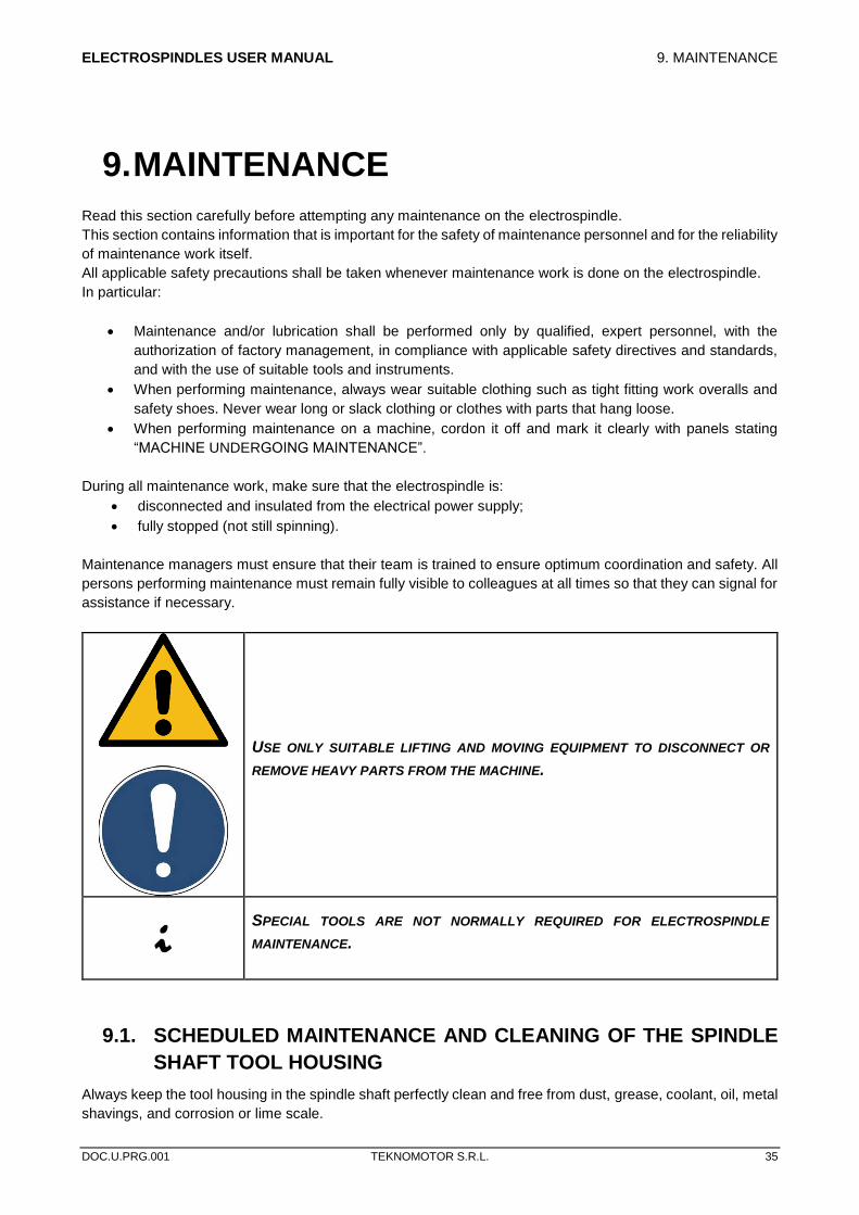
USE ONLY SUITABLE LIFTING AND MOVING EQUIPMENT TO DISCONNECT OR
REMOVE HEAVY PARTS FROM THE MACHINE.
i SPECIAL TOOLS ARE NOT NORMALLY REQUIRED FOR ELECTROSPINDLE
MAINTENANCE.
9.1. SCHEDULED MAINTENANCE AND CLEANING OF THE SPINDLE
SHAFT TOOL HOUSING
Always keep the tool housing in the spindle shaft perfectly clean and free from dust, grease, coolant, oil, metal
shavings, and corrosion or lime scale.

ELECTROSPINDLES USER MANUAL 9. MAINTENANCE
DOC.U.PRG.001 TEKNOMOTOR S.R.L. 36
Dirty housings cause incorrect tool seating, misalignment with respect to the spindle’s axis of rotation, and tool
slippage (on models without a key). Dirt can also damage the surface of the housing, causing poor machining
precision, and causing risk of injury to operating personnel.
For this reason, check at every tool change for the manual tool changing spindles and at least once a day for
the automatic tool changer electrospindle that the surfaces of the spindle shaft, taper, tool housing and tool
itself are perfectly clean.
These parts can be cleaned using standard commercial detergents for metal surfaces. When cleaning, take
the opportunity to check the condition of the surfaces for wear or damage.
9.2. OCCASIONAL MAINTENANCE
Clean the grill of the cooling fan and remove any objects blocking the airways and control the fixing screws.
i THE BEARINGS ARE LUBRICATED FOR LIFE AND DO NOT REQUIRE
GREASING.
Component parts must be removed and refitted only by authorization TEKNOMOTOR S.R.L.
ONLY REPLACEMENT OF PARTS WITH ORIGINAL TEKNOMOTOR SPARES
AND THE SUBSEQUENT ADJUSTMENT OF THE NEWLY FITTED PARTS IS
AUTHORIZED.
NO OTHER TYPE OF WORK IS AUTHORIZED AND, IF DONE, WARRANTY AND
LIABILITY UNDER GENERAL SALES CONDITIONS OF TEKNOMOTOR WILL
LAPSE.

ELECTROSPINDLES USER MANUAL 10. TROUBLESHOOTING
DOC.U.PRG.001 TEKNOMOTOR S.R.L. 37
10. TROUBLESHOOTING TABLE
PROBLEM PROBABLE CAUSE CORRECTIVE ACTION
Excessive vibration during machining
Unbalanced tool.
Incorrectly fitted tool.
Excessive cutting parameters.
Incorrect inverter settings.
Tool to big or too heavy.
Balance the tool.
Check that the tool is correctly fitted.
Adjust (reduce or increase) the various cutting parameters.
Check the inverter settings.
Try machining with smaller tools.
Bearing noise Damaged bearings. Send the electrospindle to
TEKNOMOTOR S.R.L.
The electrospindle get very hot and is stopped by the PTC
thermistor (if optioned) signal
Incorrect inverter settings.
Power settings too high.
Machining speeds too low for the power requirement.
Cooling fan grill blocked.
Cooling fan broken.
Set the inverter parameters according to the plated values.
Contact the Teknomotor Technical Office.
Check the cooling fan grill and remove any blockage.
Replace the broken fan.

ELECTROSPINDLES USER MANUAL 11. DISPOSAL
DOC.U.PRG.001 TEKNOMOTOR S.R.L. 38
11. DISPOSAL
At the end of the electrospindle working life it is the customer’s responsibility to dispose of it correctly.
First of all, clean the unit and separate the various components into mechanical and electrical parts.
Then separate the component parts according to type of material: electric motors (copper windings), metal
parts (body, etc.), plastic parts, etc.
Dispose of the various materials in compliance with the laws and regulations applicable in the country where
the electrospindle has been installed.
The expanded foam and plastic wrapping used for packaging must be disposed as plastic material.

ELECTROSPINDLES USER MANUAL 12. MANUFACTURER DECLARATION OF CONFORMITY (UE)
DOC.U.PRG.001 TEKNOMOTOR S.R.L. 39
12. MANUFACTURER DECLARATION
OF CONFORMITY (UE)

ELECTROSPINDLES USER MANUAL 12. MANUFACTURER DECLARATION OF CONFORMITY (UE)
DOC.U.PRG.001 TEKNOMOTOR S.R.L. 40

ELECTROSPINDLES USER MANUAL 12. MANUFACTURER DECLARATION OF CONFORMITY (UE)
DOC.U.PRG.001 TEKNOMOTOR S.R.L. 41
ELECTROSPINDLES USER MANUAL 12. MANUFACTURER DECLARATION OF CONFORMITY (UE)
DOC.U.PRG.001 TEKNOMOTOR S.R.L. 42

ELECTROSPINDLES USER MANUAL 12. USEFULL ADRESSES
DOC.U.PRG.001 TEKNOMOTOR S.R.L. 43
13. USEFULL ADRESSES
Headquarters: TEKNOMOTOR S.R.L.
Via Argenega, 19
32030 Quero (BL)
Italy
Tel. 0039 0439 787950
Fax 0039 0439 780147
Website: www.teknomotor.com
Sales: [email protected]
Technical Dept.: [email protected]
Quality: qualità@teknomotor.com
Administration: [email protected]
Purchase Dept.: [email protected]

ELECTROSPINDLES USER MANUAL
DOC.U.PRG.001 TEKNOMOTOR S.R.L. 44

ELECTROSPINDLES USER MANUAL
DOC.U.PRG.001 TEKNOMOTOR S.R.L. 45

ELECTROSPINDLES USER MANUAL
DOC.U.PRG.001 TEKNOMOTOR S.R.L. 46