electrospinning cover story
TRANSCRIPT

8/11/2019 Electrospinning Cover Story
http://slidepdf.com/reader/full/electrospinning-cover-story 1/622 American Ceramic Society Bulletin, Vol. 90, No. 2
c o v e r s t o r ybulletin
Developments in
electrohydrodynamicforming: Fabricating
nanomaterials from charged
liquids via electrospinning
and electrosprayingMichael J. Laudenslager and Wolfgang M. Sigmund
E lectrospinning is the process
of using an electrical charge
to pull a very thin fiber from a liquid.
Electrospinning and the related processof electrospraying comprise the larger
field known as electrohydrodynamic
forming. Electrospraying is the formation
of nanoparticles, and electrospinning
describes the fabrication of long fibrous
structures. Both processes transform liq-
uid droplets into nanomaterials through
strong electric fields that are on theorder of several kilovolts per centimeter.
These processes deserve attention by
ceramists and other materials research-
ers, because recent insights into electro-
hydrodynamic phenomena have led to
the fabrication of long nanofibers, core-
shell fibers, tubes and spherical particles
Although centuries old,
electrospinning stands out
as one of the most use-
ful and flexible techniques
for producing nanomateri-
als. Parallel to the burst of
enthusiasm in nanomaterials
in recent years, interest in
electrospinning has surged
exponentially over the
past decade as theoretical
advances in ceramics and
other materials components
have grown. As a result of
improvements in electros-
pinning modeling, process-
ing, measuring and testing,
new applications are emerg-
ing that range from health
care to high-temperature
and high-pressure filtration,
as well as new routes to
explore and control crystal
growth. Herein, our authors
from the University of
Florida describe the history
of, and current trends in,
electrospun materials.

8/11/2019 Electrospinning Cover Story
http://slidepdf.com/reader/full/electrospinning-cover-story 2/623American Ceramic Society Bulletin, Vol. 90, No. 2
with dimensions less than 100 nanome-ters. These advances are instilling new
spirit into a field that started more thanfour centuries ago.
The particular interest in electro-spinning results from its versatility.
Researchers using this technique areable to create nanofibers and nanotubes
from almost any soluble polymer anda wide range of ceramic and compos-
ite systems. Furthermore, reduction ofceramics even allows the formation of
metallic nanofibers. Fiber diameters canrange from tens of nanometers to sev-
eral micrometers. Another salient char-acteristic of electrospun fibers is their
enormous aspect ratios: The fibers canreach several meters in length while
maintaining nanometer-scale diameters.Electrospinning also provides investiga-
tors a distinctive ability to control fiberorientation, porosity and morphology.
Historical observations and earlydevelopments
For hundreds of years, seafarers havereported ominous glowing lights on the
masts of their ships during electricalstorms. Some sailors believed the light
to be a good omen and often referred to
the glow as “St. Elmo’s fire.”In reality, the conditions that caused
this glow were a warning that lightning
was likely to strike at any moment. Anelectric field concentrated at the tip
of the mast and ionized the surround-ing air molecules to create the ethereal
glow.1
A less obvious electrohydrodynamicphenomenon is that as rain falls into anelectric field, the field introduces a new
force to the droplets, one that is strongenough to change their shape and that
may even cause electrospraying.At least one early scientist took
notice of this effect on liquids. WilliamGilbert first recorded the curious
behavior of liquid droplets in electricfields around 1600.2 Gilbert devised
several experiments to demonstrate
the distinct behaviors of electricity andmagnetism. His observations were pub-lished in his work, De Magnete. Using
charged amber, he was able to deformthe shape of water droplets without
physical contact. This descriptionstarted the study of electrohydrodynam-
ics. Although the practical applicationsof this phenomenon were not imme-
diately realized, demonstrations of itseffects were used to entertain (Figure
1). Despite Gilbert’s work, the next
known publication related to this fielddid not appear until 1882, when Lord
Rayleigh published a theoretical modelthat describes electrical forces needed
to cause droplets to eject liquid.3 In the 1960s, Sir Geoffrey Taylor
became the first to undertake a rigor-ous theoretical study on charged liquid
droplets. Taylor observed how dropletsunder an electric field could deform
into a new equilibrium shape thatresembled a cone.2,4 These so-called
Taylor cones emitted fluid from theirtip. He discovered that the ejected fluid
could exhibit two distinctive behaviors,either forming discrete droplets that
travel directly to the counterelectrodeplate or forming long strands of liquid
that whip around before reaching theelectrode.5
An important breakthrough to thisfield occurred when researchers began
incorporating polymers dissolved involatile solvents into the electric field.
As the droplets travel through the elec-tric field, the solvent evaporates, leav-
ing behind polymeric nanostructures.
This phenomenon does not occurwith all polymers. Low-molecular-
weight polymers typically form thedroplets that are the signature of elec-
trospraying. However, the rheological
properties of high-molecular-weightpolymers prevent the material frombreaking apart into spheres. Instead,
long, continuous polymer fibers areemitted.6
Attempts to commercialize thisphenomenon began to appear in 1902,
when two patents were granted thatdescribed methods to electrically dis-
perse water droplets.7,8 Anton Formhalswas the first to lay claim to the process
of electrospinning in a 1934 patent.9 In
1936, Petryanov-Sokolov ingeniouslydeveloped one of the first applicationsfor electrospun fibers: filtration. The
underlying reasoning for Petryanov-Sokolov’s innovation comes from filtra-
tion theory, which holds that thinnerfibers make more efficient filter mate-
rial. Indeed, industrial-scale productionof these filters began shortly thereafter
in the former Soviet Union.10 Despite Petryanov-Sokolov’s break-
through, intensive and detailed study
into the behavior of electrically chargedfluids did not begin until the early
1980s.
The modern era of electrospinningIndustrial-scale electrospinning
equipment can be quite complicated.However, at the laboratory scale, rela-
tively simple setups are used to producefibers. The essential components of a
typical laboratory-scale electrospinningsetup, shown in Figure 2, are an electri-
cally charged capillary attached to anadvancement pump and a grounded
collection plate.Pressure from the advancement
pump causes the capillary to emita small droplet of the viscous poly-
mer–solvent liquid. The electric fieldstretches the droplet, which forms a
Taylor cone, and soon accelerates anelongated strand of solution onto a
grounded substrate. The solvent beginsto evaporate as soon as it is emitted
from the needle.The fiber does not travel in a
Fig. 1: Electrospraying devices used forentertainment purposes. Published inEssai Sur L’ El électricité Des Corps in1746.

8/11/2019 Electrospinning Cover Story
http://slidepdf.com/reader/full/electrospinning-cover-story 3/624 American Ceramic Society Bulletin, Vol. 90, No. 2
straight line. One characteristic of elec-trospinning is that electrostatic forces
cause the material to whip around. Thismotion helps thin the fibers and accel-
erates the solvent evaporation. The end
result is a collection of solid nanofibers,
and in this collection-plate setup, thefibers deposit in a randomly entangledmesh. The fibers then can be separated
from the substrate and used in a num-ber of applications.
Perhaps the most interesting aspectof electrospinning is its versatil-
ity. Investigators have demonstratedthat a wide range of material systems
can be transformed into nanofibers.Furthermore, with additional modifica-
tions to the process, one can produce a
variety of structures and morphologies.For example, small particles, salts andceramic precursors easily can be added
to the polymer–solvent solution, whichis then electrospun into fibers bearing
those materials. This further enhancesthe variety of materials that can be
electrospun.11-15 Researchers haveshown that the polymer–solvent is not
always a requirement by electrospinningpolymerless sol–gel systems.16
Postelectrospinning steps often arenecessary to modify the final electro-
spun fibers. Heat treatments can be
used to carbonize polymer fibers or
burn out the polymer material to formentirely ceramic fibers.17 Although
the vast majority of electrospinningresearch is focused on polymeric and
ceramic materials, investigators also
have demonstrated that ceramic fiberscan be reduced to form metallic fibers.18 Another study has utilized electrospun
fibers as templates for forming metallicnanotubes.19
Additional modifications to the elec-trospinning setup have led to a diverse
collection of unique nanostructures. In2003, Sun et al.20 demonstrated that
separate polymer solutions could bepumped into different compartments
of concentric capillaries to electrospin
core-shell fibers. A year later, Li etal.21,22 produced hollow fibers by replac-ing the inner capillary fluid with heavy
mineral oil, which was extracted afterelectrospinning.
Although the classic electrospinningapproach produces fibers collected in
a randomly oriented nonwoven mat,several research teams have developed
modified collector setups that orientfibers along a single axis to produce
aligned nanofibers.14,23–29 In fact, we
now know that there is a useful variety
of morphologies that are possible withelectrospun fibers (Figure 3).
Theoretical developments Numerous models exist that describe
the electrospinning and electrosprayingprocesses. A series of papers, publishedby Hohman and Shin31–33 in 2000
describes the whipping motion of elec-trospun jets. Instabilities in the electric
field cause the fiber to whip around. Arefinement of the analysis was subse-
quently published by Feng.34 Obtaining very thin fibers is of para-
mount importance for many electros-pun applications. To this end, theoreti-
cal models were developed to determine
how various electrospinning parametersaffect the final fiber diameter. Fridrikhet al.35 proposed a model to predict the
final fiber diameter of electrospun sys-tems. They used their model to achieve
an accuracy of around 10 percent for apoly(ethylene oxide) system. (Several
numerical approaches also have beenused to model the electrospraying pro-
cess, which are summarized in severalreviews.36,37)
High conductivity in ceramic sys-
Developments in electrohydrodynamic forming
Fig. 2: Typical laboratory-scale electrospin-ning apparatus that allows productionof milligram to gram amounts of ceramicnanofibers.
Fig. 3: (a) Hollow, aligned electrospun fibers; (b) Beaded, aligned polystyrene fibers;(c) Porous surface of a polystyrene fiber; and (d) Random mesh of TiO
2 fibers. (a) and
(c) reprinted with permission from References 21 and 30, respectively. Copyrights2004 and 2002, American Chemical Society.
8/11/2019 Electrospinning Cover Story
http://slidepdf.com/reader/full/electrospinning-cover-story 4/625American Ceramic Society Bulletin, Vol. 90, No. 2
tems invalidates several of the assump-
tions presented in previous models. Toaccommodate for the higher conduc-
tivities of these systems, Sigmund etal.13 proposed a model for ceramic sys-
tems. These equations act as guides for
determining which parameters have thegreatest impact on the final fiber diam-eter. However, they have limitations.
The equations assume all materials canbe electrospun and that the fibers are
continuous and uniform. In practice,some materials cannot be electrospun.
Furthermore, certain conditions notaccounted for in the equations result
in nonuniform fibers because of theformation of beads and pores within the
strands (Figures 3(b) and 3(c)).38–41
Experimental developmentsOur current research encompasses
several areas in electrospinning witha particular focus on advancing the
theoretical understanding and process-ing of ceramic nanofibers. Central to
this pursuit is improving the propertiesof ceramic fibers, which are typically
polycrystalline and brittle. Often, nano-fibers fracture during heat treatment or
shatter when handled. To improve the
practical applications of ceramic fibers,our research group has conducted sev-eral studies to overcome these hurdles.
One achievement is that we establisheda three-point bending technique using
atomic force microscopy to measurethe mechanical properties of individual
ceramic nanofibers.42
Later developments have led toceramic nanofibers of sufficient strength
for filtration purposes. These fibersare easily handled after the sintering
process. Because of their strength andchemical stability, these fibers may be
of particular interest to filtration appli-cations where extreme conditions may
be encountered.43 Ceramic nanofibers offer interesting
opportunities to control crystal growth.Grain growth in nanofibers is hindered
by their 2D structures so that grainsizes in electrospun fibers are typically
smaller than those produced by otherprocessing methods.44 Small grains
improve many ceramic properties.Therefore, there also is a great inter-
est in synthesizing single-crystal fibers.
This is a challenge that could improve
their electrical, mechanical and opticalproperties. Yuh et al.45 synthesized sin-gle-crystal fibers composed of BaTiO
3
by carefully controlling the processingconditions. These fibers also represent
the first complex oxide electrospun fer-roelectric structures.
Growing applicationsAs noted earlier, one of the predomi-
nant applications of electrospun fibers
is in filtration systems. Improvements
continue to be made in this field asvarious types of fibers are studied, andtechniques to upscale the electrospin-
ning process are developed.10 However, electrospinning is not lim-
ited to filtration: It is applied to severaldisparate fields. For example, the ability
to process biocompatible fibers fromnonhazardous solvents is of interest to a
variety of biomedical applications, suchas scaffolds for cell growth. Numerous
studies also demonstrate the usefulnessof fibers for wound healing and tissue
engineering.46–48 Energy applications,
such as solar cells, batteries, capacitors
and fuel cells, also have made use of
electrospun fibers.11,49
The ability to produce fibers from
such a vast range of materials ensures
that the number of new applicationswill not be exhausted anytime soon.
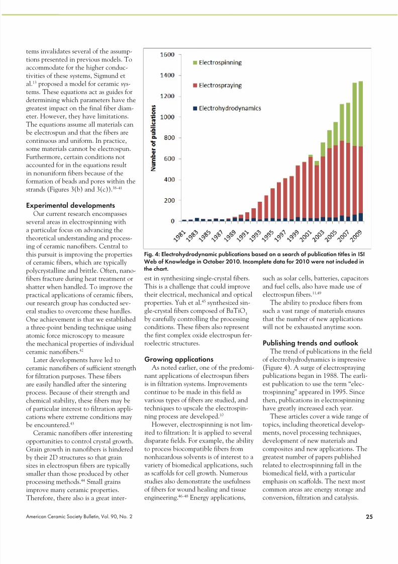
Publishing trends and outlookThe trend of publications in the field
of electrohydrodynamics is impressive
(Figure 4). A surge of electrosprayingpublications began in 1988. The earli-
est publication to use the term “elec-
trospinning” appeared in 1995. Sincethen, publications in electrospinninghave greatly increased each year.
These articles cover a wide range oftopics, including theoretical develop-
ments, novel processing techniques,development of new materials and
composites and new applications. Thegreatest number of papers published
related to electrospinning fall in thebiomedical field, with a particular
emphasis on scaffolds. The next mostcommon areas are energy storage and
conversion, filtration and catalysis.
Fig. 4: Electrohydrodynamic publications based on a search of publication titles in ISIWeb of Knowledge in October 2010. Incomplete data for 2010 were not included inthe chart.

8/11/2019 Electrospinning Cover Story
http://slidepdf.com/reader/full/electrospinning-cover-story 5/626 American Ceramic Society Bulletin, Vol. 90, No. 2
Developments in electrohydrodynamic forming
Interest in electrospinning contin-ues to gain momentum. Processing
innovations are expanding the range ofmorphologies and production quantities
of fibers. The variety of materials thatcan be electrospun opens the technique
to many avenues of research, many ofwhich remain undiscovered.
Methods to improve the productioncapacity of electrospun fibers are an
ongoing development by several com-panies. Innovative techniques have rad-
ically altered the electrospinning setupto make use of multiheaded jets and
needleless systems. However, consis-tently producing large quantities (tons)
of fibers remains the greatest challengeto the industrial use of the process. n
About the authorsMichael J. Laudenslager is a gradu-
ate student and Wolfgang M. Sigmund
is a professor in the Department ofMaterials Science and Engineeringat Florida State University. Professor
Sigmund’s areas of interest includeaerosol filters, water filters, filter regen-
eration, electrospinning, nanofiber fil-ters, nanoparticles and photocatalysis.
References1E. Wescott, D. Sentman, M. Heavner, D.Hampton and O. Vaughan, J. Atmos. Sol.-Terr. Phys., 60, 713 (1998).
2W. Gilbert and P. Mottelay, De Magnete,Dover Publications, 1958.3L. Rayleigh, Philos. Mag , 14, 184 (1882).4G. Taylor, Proc R. Soc. London, A, Math.Phys. Sci., 383 (1964).5R. Hartman, D. Brunner, D. Camelot, J.Marijnissen and B. Scarlett, J. Aerosol Sci.,31, 65 (2000).6A. Ga án-Calvo, J. Davila and A. Barrero,
J. Aerosol Sci., 28, 249 (1997).7W. Morton, U.S. Pat. No. 705,691, July 29,1902.8
J. Cooley, U.S. Pat. No. 692,631, Feb. 4, 1902.
9A. Formhals, U.S. Pat. No. 1,975,504, Oct.2, 1934.10R. Barhate and S. Ramakrishna, J. Membr.Sci., 296, 1 (2007).11S. Ramakrishna, K. Fujihara, W. Teo, T.Yong, Z. Ma and R. Ramaseshan, Mater.Today, 9, 40 (2006).12T. Subbiah, G. Bhat, R. Tock, S.Parameswaran and S. Ramkumar, J. Appl.Polym. Sci., 96, 557 (2005).
13W. Sigmund, J. Yuh, H. Park, V.Maneeratana, G. Pyrgiotakis, A. Daga, J.Taylor and J. Nino, J. Am. Ceram. Soc., 89,395 (2006).14W. Teo, W. and S. Ramakrishna,
Nanotechnology, 17, 89 (2006).15Z. Huang, Y. Zhang, K. Kotaki and S.Ramakrishna, Compos. Sci. Technol., 63,2223 (2003).16W. Son, D. Cho and W. Park,
Nanotechnology, 17, 439 (2006).17Y. Wang, S. Serrano and J. Santiago-Aviles, Synth. Met., 138, 423 (2003).
18H. Wu, R. Zhang, X. Liu, D. Lin and W.Pan, Chem. Mater, 19, 3506 (2007).19F. Ochanda and W. Jones Jr., Langmuir, 21,10791 (2005).20Z. Sun, E. Zussman, A. Yarin, J. Wendorffand A. Greiner, Adv. Mater., 15, 1929(2003).21D. Li and Y. Xia, Nano Lett., 4, 933(2004).22I. Loscertales, A. Barrero, M. Márquez, R.Spretz, R. Velarde-Ortiz and G. Larsen, J.
Am. Chem. Soc, 126, 5376 (2004).23B. Sundaray, V. Subramanian, T.
Natarajan, R. Xiang, C. Chang and W.Fann, Appl. Phys. Lett., 84, 1222 (2004).24H. Pan, L. Li, L. Hu and X. Cui, Polymer,47, 4901 (2006).25D. Li, Y. Wang and Y. Xia, Adv. Mater.,16, 361 (2004).26D. Li, Y. Wang and Y. Xia, Nano Lett., 3,1167 (2003).27A. Theron, E. Zussman and A. Yarin,
Nanotechnology, 12, 384 (2001).28 J. Deitzel, J. Kleinmeyer, J. Hirvonen and
N. Beck Tan, Polymer, 42, 8163 (2001).
29D. Yang, B. Lu, Y. Zhao and X. Jiang, Adv.Mater, 19, 3702 (2007).30S. Megelski, J. Stephens, D. Chase and J.Rabolt, Macromolecules, 35, 8456 (2002).31Y. Shin, M. Hohman, M. Brenner andG. Rutledge, Appl. Phys. Lett., 78, 1149(2001).32Y. Shin, M. Hohman, M. Brenner and G.Rutledge, Polymer, 42, 09955 (2001).33M. Hohman, M. Shin, G. Rutledge and M.
Brenner, Phys. Fluids, 13, 2201 (2001).34 J. Feng, Phys. Fluids, 14, 3912 (2002).35S. Fridrikh, J. Yu, M. Brenner and G.Rutledge, Phys. Rev. Lett., 90, 144502(2003).36 J. Grace and J. Marijnissen, J. Aerosol Sci.,25, 1005 (1994).37A. Jaworek and A. Sobczyk, J.Electrostatics, 66, 197 (2008).38H. Dong, V. Nyame, A. MacDiarmid andW. Jones Jr., J. Polym. Sci., Part B: Polym.Phys., 42 (2004).39
J. Deitzel, J. Kleinmeyer, D. Harris and N.Beck Tan, Polymer, 42, 261 (2001).40C.L. Casper, J.S. Stephens, N.G. Tassi,D.B. Chase and J.F. Rabolt, Macromolecules,37, 573 (2003).41M. Hey, D. Jackson and H. Yan, Polymer,46, 2567 (2005).42S. Lee, C. Tekmen and W. Sigmund,Mater. Sci. Eng. A, 398, 77 (2005).43H. Park, Ph.D. Thesis, University ofFlorida, 2010.44Y. Wang, M. Aponte, N. Leon, I. Ramos,R. Furlan, N. Pinto, S. Evoy and J. Santiago
Avilés, J. Am. Ceram. Soc., 88, 2059(2005).45 J. Yuh, J. Nino and W. Sigmund, Mater.Lett., 59, 3645 (2005).46K. Rho, L. Jeong, G. Lee, B. Seo, Y. Park,S. Hong, S. Roh, J. Cho, W. Park and B.Min, Biomaterials, 27, 1452 (2006).47Q. Pham, U. Sharma and A. Mikos, TissueEng., 12, 1197 (2006).48 J. Matthews, G. Wnek, D. Simpson and G.Bowlin, Biomacromolecules, 3, 232 (2002).49V. Thavasi, G. Singh and S. Ramakrishna,Energy Environ. Sci., 1, 205 (2008).
Electrospinning droplet deformation. C r e d i t : M . J .
L a u d e n s l a g e r a n d W . M .
S i g m u n d .

8/11/2019 Electrospinning Cover Story
http://slidepdf.com/reader/full/electrospinning-cover-story 6/627American Ceramic Society Bulletin, Vol. 90, No. 2 27American Ceramic Society Bulletin, Vol. 90, No. 2
Electrospraying and electrospinning have
proved to be valuable methods for custom
and small-volume applications. However, as
Laudenslager and Sigmund note, finding high-
volume electrodynamic processes is a challenge
to engineers and manufacturers.
The building of high-throughput systems and
equipment capable of producing well-controlledand narrow particle- or fiber-sized distributions at
massive rates is not easy because there is not
a universal or unique solution in terms of device
geometry and device parametric operating range.
The Taylor cone must undergo dynamic pro-
cesses that can be dramatically different in each
application. The process depends on the type of
particles or fibers to be produced and on the sub-
stances and materials involved in the particle- or
fiber-formation process.
A trustable upscaling of production must
start from the study and characterization of the
most basic setup: the single-needle electrospray
or electrospinning process. Once the basic
characterization of the materials, solvents and
equipment has been established, there is plenty
of room to innovate and reach higher volumes.
Two particularly intriguing methods are multi-
needle (multinozzle) processes and – even more
extreme – needleless processes, as exemplified
by the commercial work of Yflow and Elmarco,
respectively.
Fifty nozzles are better than oneYflow (www.yflow.com) was founded in 2001
by scientists from the Universities of Málaga
and Seville in Spain and has since developedoutstanding know-how in using devices with
heads that contain scores of nozzles to create
nanofibers, coaxial fibers, hollow capsules and
filled capsules.
Yflow says that, once the single-needle for-
mation process is properly characterized, it then
tests a multinozzle piece. This is a “first-order
upscaling,” where the objective is to increase
the particle or fiber yield by one or two orders of
magnitude. The reason for this step is that, when
separate single-needle processes are brought
close to each other, Yflow typically sees the par-
ticles or fibers exhibit a strong interaction among
themselves, This may deteriorate the quality of
the particles/fibers as well as break down the
whole process. Again, such interaction strongly
depends on the physical and chemical proper-
ties of the fluids as well as on the geometry of
the multinozzle piece. The optimization of the
first-upscaling step allows operators to define an
initial “building block.”
In the next step, the objective is to increase
the particle/fiber yield by three or four orders
of magnitude. Here, the initial building block
is repeated and integrated in a basic upscal-
ing modulus. Yflow says that, even though the
design has been optimized to produce a specificmaterial, the modulus then can be readjusted
easily to yield various
types of particles or
fibers by substitut-
ing other multinozzle
pieces that have been
optimized for a different
type of material. Similar
adjustments can bemade to produce the
same materials but in
various sizes.
The actual modules
are intended to operate as completely indepen-
dent units, such that no “cross-talking” occurs
when several are placed next to each other.
Thus, the final level of production required by a
customer may be supplied by grouping as many
of those modules as needed. An additional ben-
efit of this modular scheme is that it allows much
easier maintenance of the units.
Another essential aspect of the mass produc-
tion is the collection system for the particles
or fibers. Some Yflow customers are seeking
nonwoven mats of nanofibers that will be applied
later on certain substrates or be subjected to
postprocessing. In some cases, a conveyor-type
collector works well. However, there are situa-
tions in which the fibers must land on specific
substrates in such a way that the multinozzle
module must move in a certain fashion above
the substrates.
For other applications, the desired product
is spheres (capsules, for instance). Depending
on the materials they are made of, the capsules
may be tremendously sticky. In these scenarios,special care must be taken to select the collec-
tor material in order to efficiently remove the
microcapsules or nanocapsules afterward. For
certain applications, the capsules might need to
be postprocessed before they gain mechanical
rigidity (such as in the case of liquid capsules).
Therefore, collection must be performed in a
liquid collector instead of a solid one.
No needles are better than oneThe Czech Republic-based Elmarco (www.
elmarco.com) makes use of a discovery by which
it is possible to produce Taylor cones and mate-
rial flows from a tip of a needle or nozzle or from
a thin film of polymer solution. In its patented
Nanospider nozzleless process, multiple fiber
“jets” form spontaneously from a thin film, which
is carried on the surface of a rotating drum, when
the drum is exposed to a high-voltage electric
field of a critical value.
The number and location of the jets spread
out on the drum depend on a number of factors,
including temperature, conductivity, liquid den-
sity, surface tension and electric-field strength.
Elmarco says it avoids some of the multinozzle
process steps by letting the jets set up naturally,
noting, “[F]ree liquid surface electrospinning letsnatural physics define this distance, rather than
using individual needles. This allows higher fiber
packing density and, thus, an increased produc-
tivity as well as better fiber homogeneity and
more consistent web morphology.”
Elmarco says another benefit is more homog-
enous fiber layers. A final benefit of a nozzleless
process is easier maintenance and cleanup:
There are no needles or nozzles to unclog or
clean.
As these examples imply, the possibilities forusing electrospinning and spraying are almost
as many as material combinations and applica-
tions. However, it is precisely this broad scope
that prevents the upscaling from having a unique
solution.n
Electrospinning and electrospraying: Turning up the volume
Elmarco’s Nanospider nozzleless processcan allow a large number of jets to form
naturally out of a thin film of a polymersolution.
Yflow’s approach to increasing volume is to use arrays of multi-nozzle modules.
C r e d i t : Y f l o w
C r e d i t : E l m a r c o .