eleg 635 digital communication theory lecture 9 …mirotzni/eleg635/eleg635 digital... · eleg 635...
TRANSCRIPT
ELEG 635 Digital Communication Theory
Lecture 9
10252012

Agenda● Optimal receiver for PSK
● Effects of fading on BER performance
– Two ray model
● Pulse shaping
– Rectangle
– Raised cosine
– Root raised cosine
– Receivers and pulse shaping
● FSK receiver
– Coherent
– Non-coherent
● CPM receiver
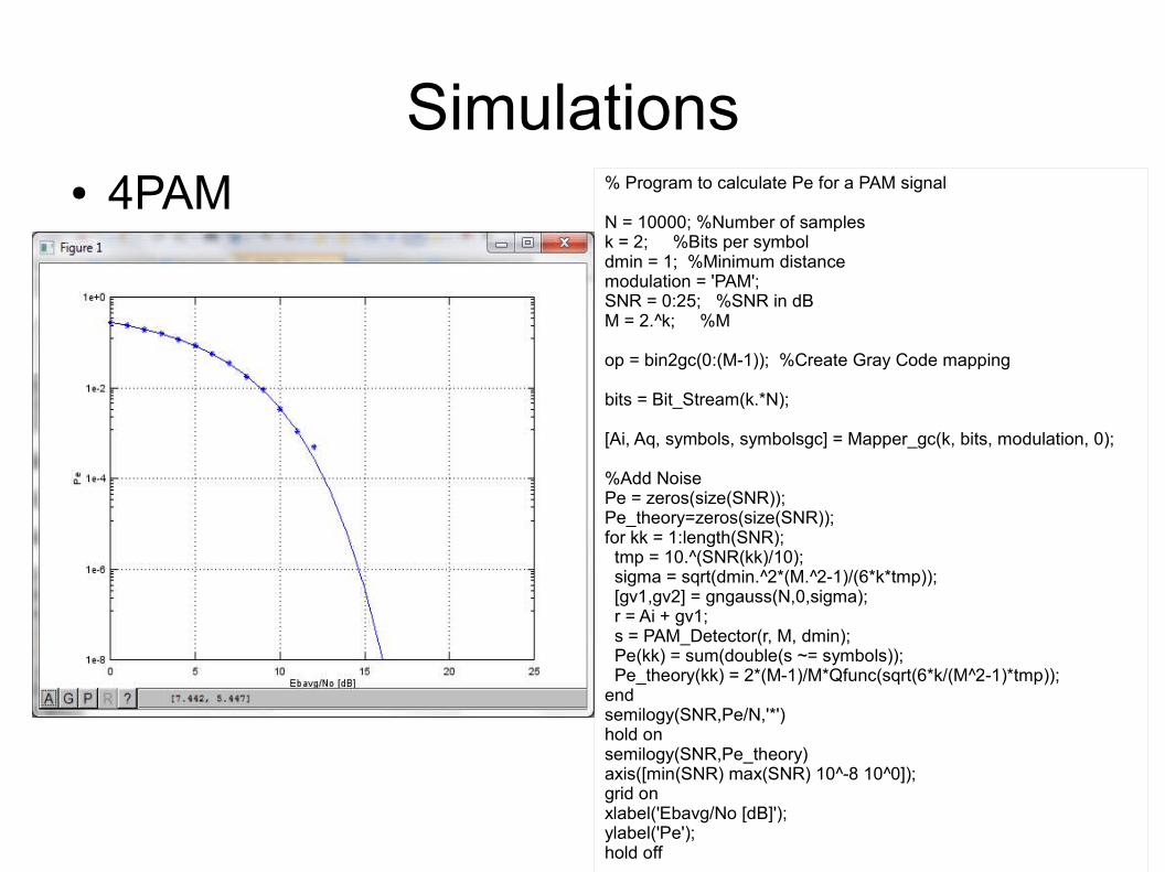
Simulations ● 4PAM % Program to calculate Pe for a PAM signal
N = 10000; %Number of samplesk = 2; %Bits per symboldmin = 1; %Minimum distancemodulation = 'PAM';SNR = 0:25; %SNR in dBM = 2.^k; %M
op = bin2gc(0:(M-1)); %Create Gray Code mapping
bits = Bit_Stream(k.*N);
[Ai, Aq, symbols, symbolsgc] = Mapper_gc(k, bits, modulation, 0);
%Add NoisePe = zeros(size(SNR));Pe_theory=zeros(size(SNR));for kk = 1:length(SNR); tmp = 10.^(SNR(kk)/10); sigma = sqrt(dmin.^2*(M.^2-1)/(6*k*tmp)); [gv1,gv2] = gngauss(N,0,sigma); r = Ai + gv1; s = PAM_Detector(r, M, dmin); Pe(kk) = sum(double(s ~= symbols)); Pe_theory(kk) = 2*(M-1)/M*Qfunc(sqrt(6*k/(M^2-1)*tmp));endsemilogy(SNR,Pe/N,'*')hold onsemilogy(SNR,Pe_theory)axis([min(SNR) max(SNR) 10^-8 10^0]);grid onxlabel('Ebavg/No [dB]');ylabel('Pe');hold off
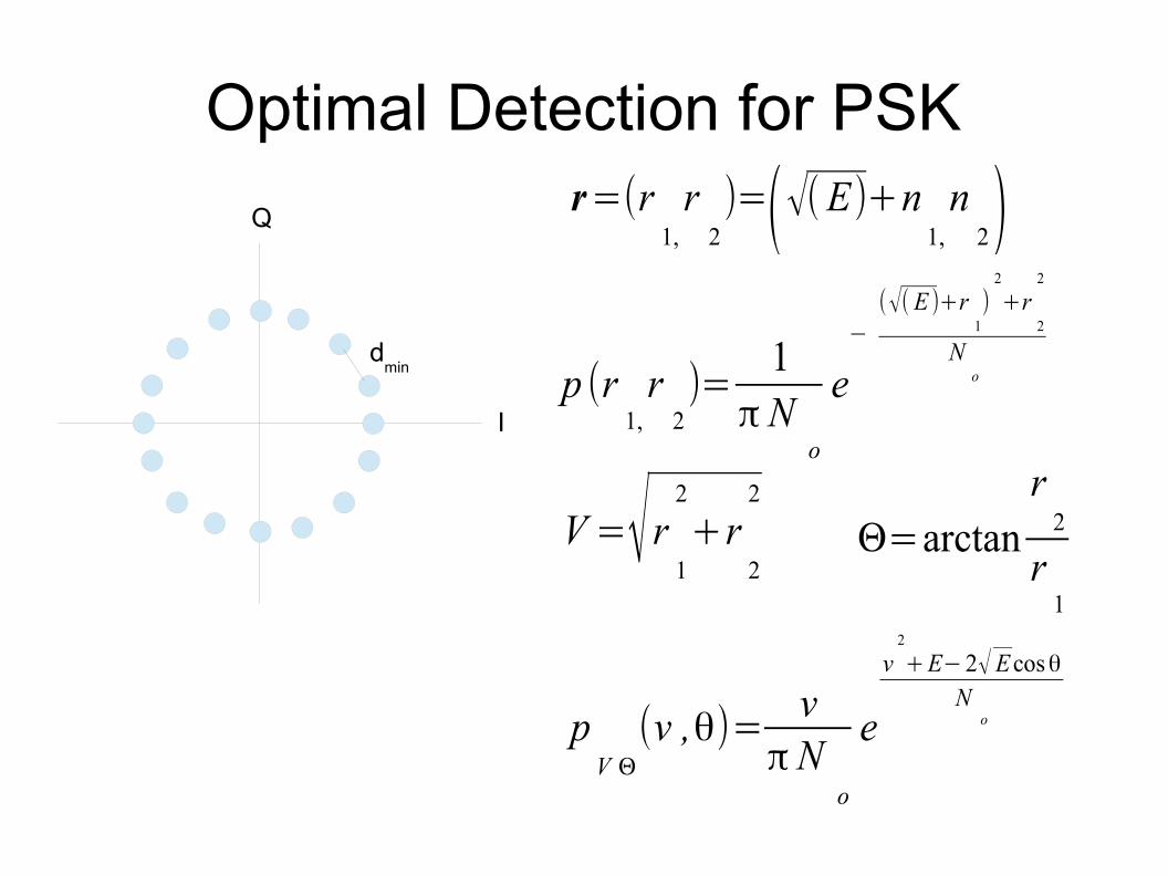
Optimal Detection for PSK
I
Q
dmin
r=(r1,r
2)=(√(E)+n
1,n
2)
p (r1,r
2)=
1π N
o
e−
(√(E )+r1
)2
+r2
2
No
V =√r1
2
+r2
2
Θ=arctanr
2
r1
pV Θ
(v ,θ)=v
πNo
e
v2
+E−2√ Ecosθ
No
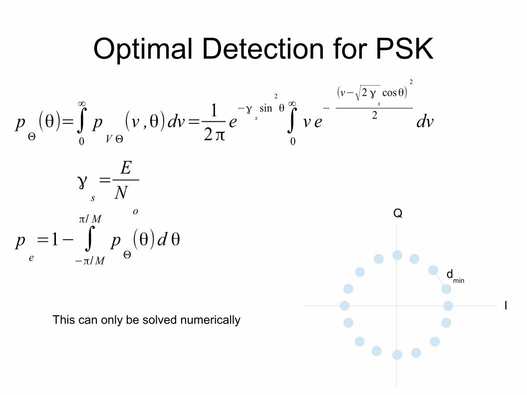
Optimal Detection for PSK
I
Q
dmin
pΘ(θ)=∫
0
∞
pV Θ
(v ,θ)dv=1
2πe
−γssin
2
θ
∫0
∞
v e−
(v−√2 γs
cosθ)2
2 dv
γs=
EN
o
pe=1− ∫
−π/M
π/ M
pΘ(θ)d θ
This can only be solved numerically
Frequency Selective Fading
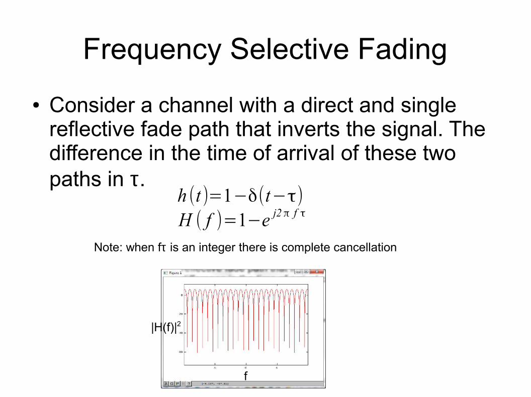
● Consider a channel with a direct and single reflective fade path that inverts the signal. The difference in the time of arrival of these two paths in τ.
h (t )=1−δ(t−τ)
H ( f )=1−e j2π f τ
Note: when fτ is an integer there is complete cancellation
|H(f)|2
f
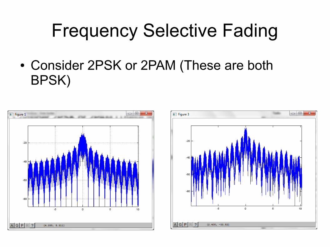
Frequency Selective Fading
● Consider 2PSK or 2PAM (These are both BPSK)
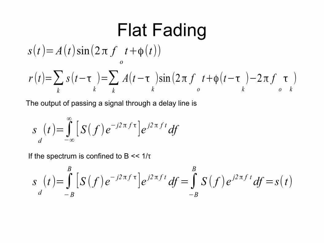
Flat Fadings(t )=A(t )sin(2π f
ot+ϕ(t ))
r (t)=∑k
s (t−τk)=∑
k
A(t−τk)sin (2π f
ot+ϕ(t−τ
k)−2π f
oτ
k)
The output of passing a signal through a delay line is
sd(t )=∫
−∞
∞
[ S ( f )e− j2 π f τ ]e j2 π f tdf
If the spectrum is confined to B << 1/τ
sd(t )=∫
−B
B
[S ( f )e− j2 π f τ ]e j2 π f t df =∫−B
B
S ( f )e j2π f tdf =s( t)

Flat Fading
r (t)=A(t)[sin(2π fot+ϕ)∑
k
αkcos(2π f
oτ
k)−cos(2π f
ot+ϕ)∑
k
αksin (2π f
oτ
k)]
r (t)=A(t)[a( t)sin (2π fot+ϕ(t))+b (t)cos(2π f
ot+ϕ(t ))]
r (t)=A(t)M (t )sin(2π fot+ϕ(t )+θ(t ))
M (t)=√a(t )2
+b( t)2
θ(t )=arctana (t )b(t)
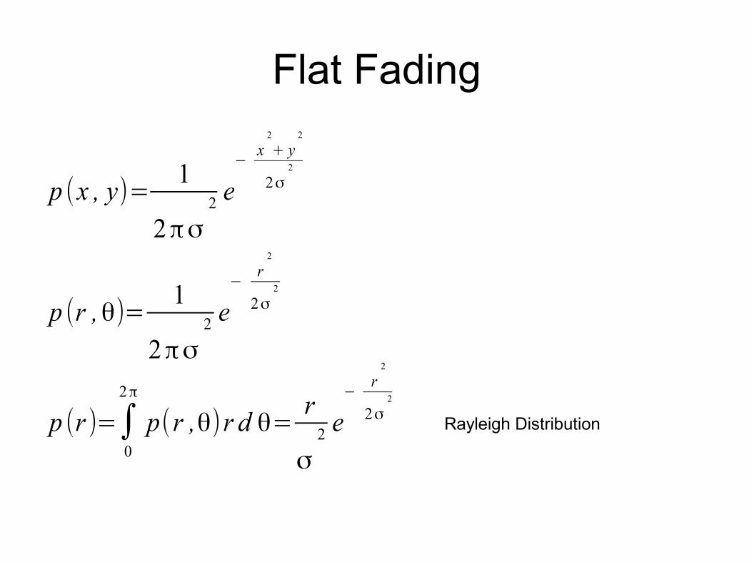
Flat Fading
p (x , y)=1
2πσ2 e
−x
2
+ y2
2σ2
p (r ,θ)=1
2πσ2 e
−r
2
2σ2
p (r )=∫0
2π
p(r ,θ)r d θ=r
σ2 e
−r
2
2σ2
Rayleigh Distribution
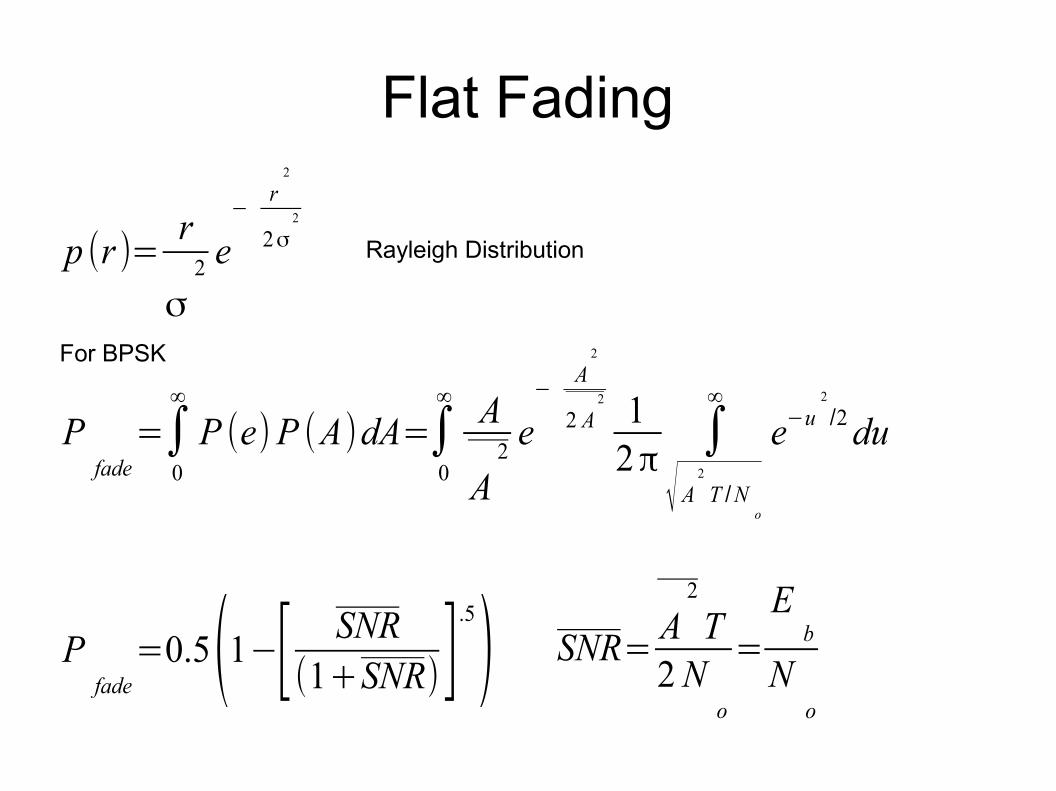
Flat Fading
p (r )=r
σ2 e
−r
2
2σ2
Rayleigh Distribution
Pfade
=∫0
∞
P (e)P (A)dA=∫0
∞ A
A2e
−A
2
2 A2 1
2π∫
√ A2
T /No
∞
e−u2
/2du
For BPSK
Pfade
=0.5(1−[ SNR(1+SNR)]
.5
) SNR=A
2
T2 N
o
=
Eb
No
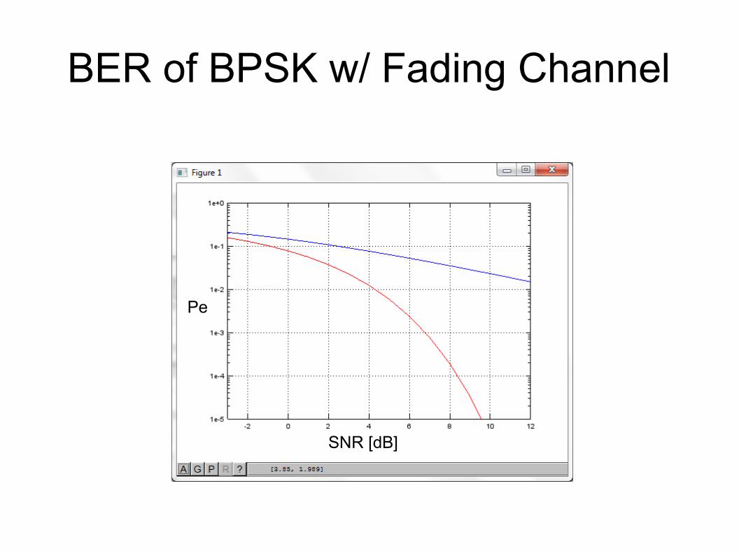
BER of BPSK w/ Fading Channel
Pe
SNR [dB]
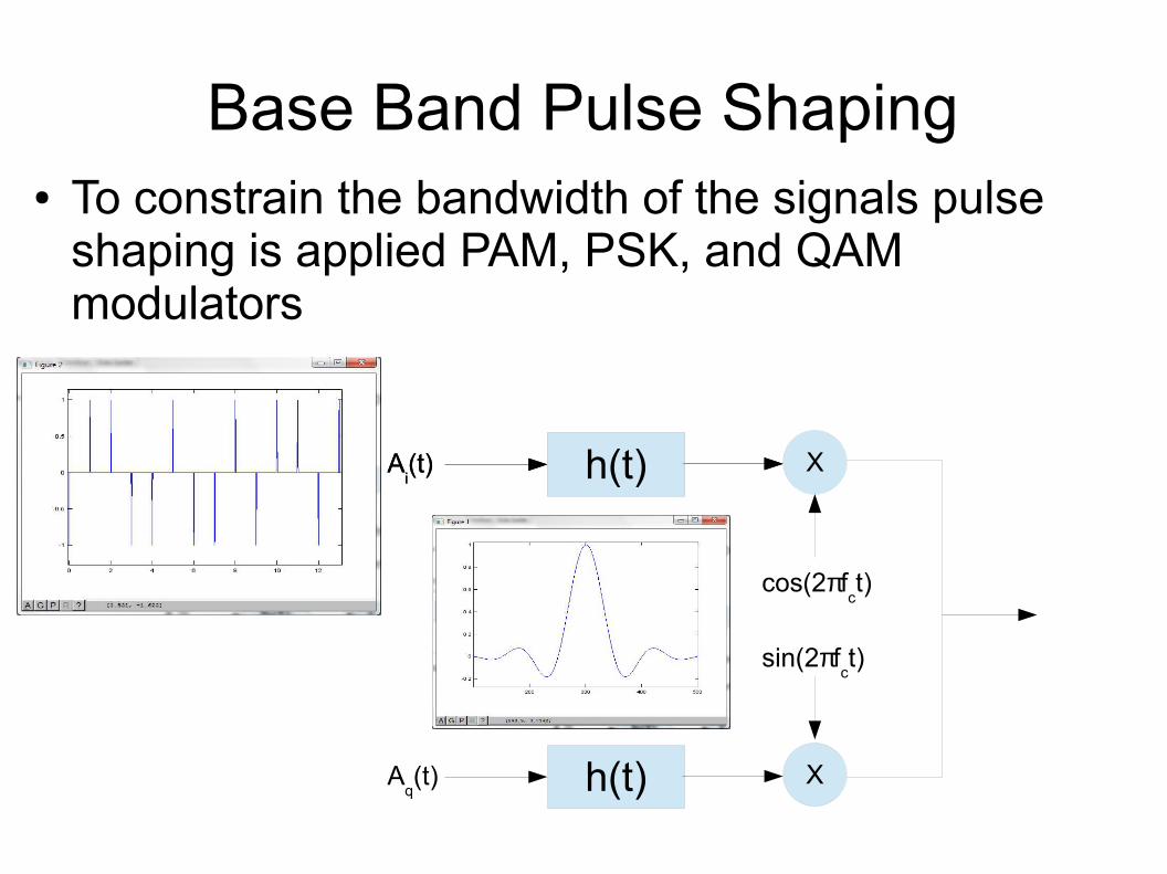
Base Band Pulse Shaping● To constrain the bandwidth of the signals pulse
shaping is applied PAM, PSK, and QAM modulators
Xh(t)
cos(2πfct)
Ai(t)
X
sin(2πfct)
h(t)Aq(t)
h(t)Ai(t)
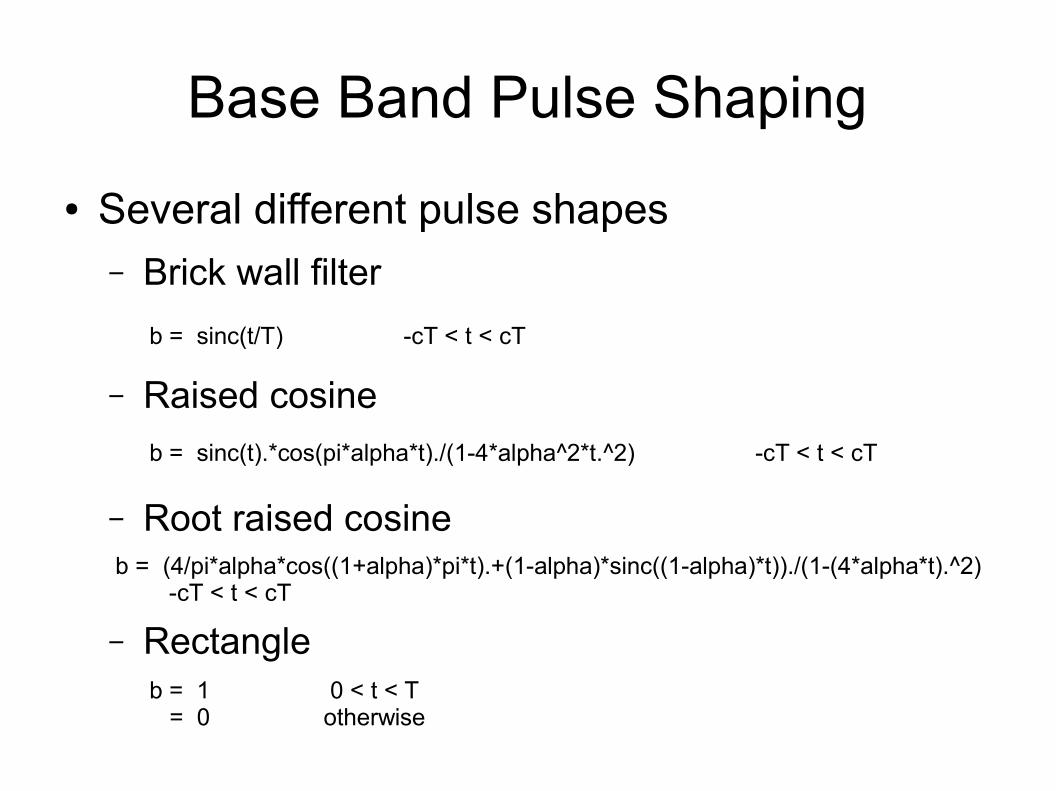
Base Band Pulse Shaping
● Several different pulse shapes– Brick wall filter
– Raised cosine
– Root raised cosine
– Rectangle
b = sinc(t/T) -cT < t < cT
b = sinc(t).*cos(pi*alpha*t)./(1-4*alpha^2*t.^2) -cT < t < cT
b = (4/pi*alpha*cos((1+alpha)*pi*t).+(1-alpha)*sinc((1-alpha)*t))./(1-(4*alpha*t).^2) -cT < t < cT
b = 1 0 < t < T = 0 otherwise
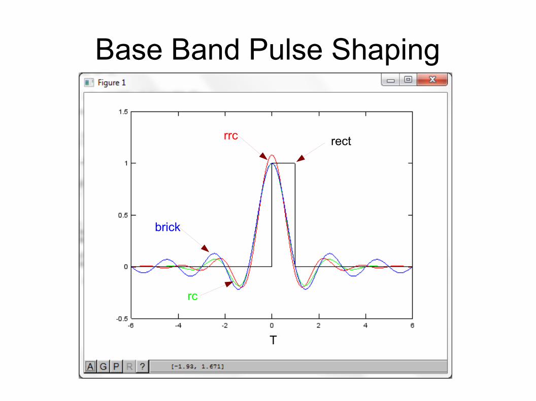
Base Band Pulse Shaping
rrc
brick
rect
rc
T
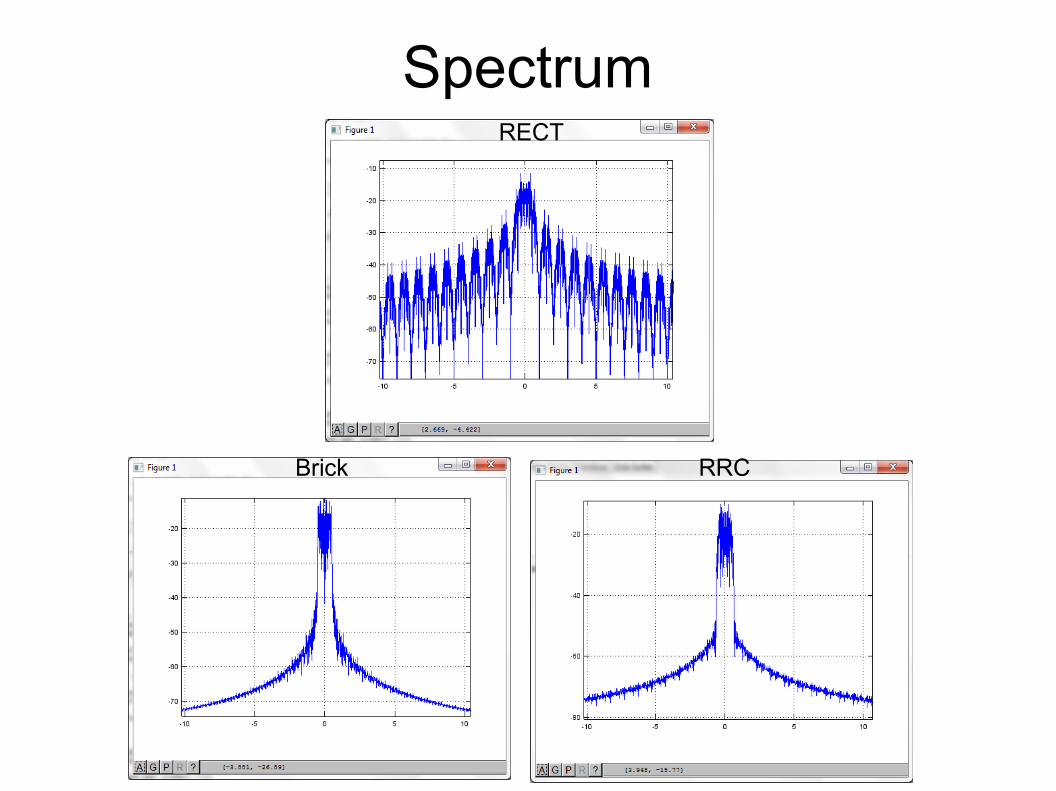
Spectrum
Brick RRC
RECT
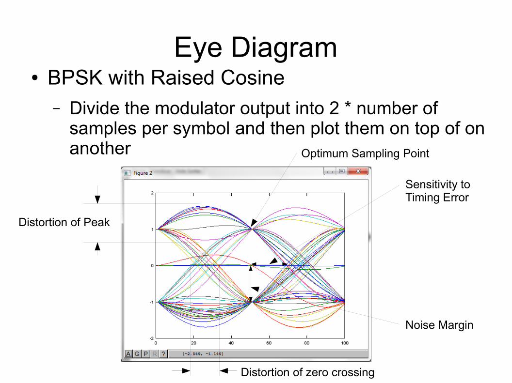
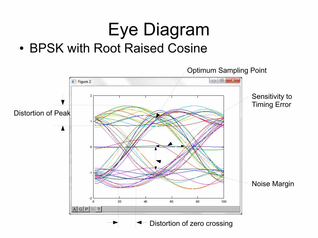
Eye Diagram● BPSK with Raised Cosine
– Divide the modulator output into 2 * number of samples per symbol and then plot them on top of on another
Noise Margin
Distortion of zero crossing
Distortion of Peak
Sensitivity toTiming Error
Optimum Sampling Point
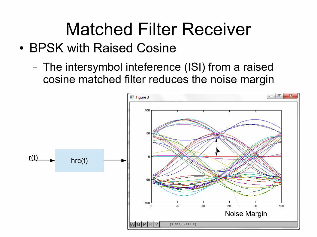
Matched Filter Receiver● BPSK with Raised Cosine
– The intersymbol inteference (ISI) from a raised cosine matched filter reduces the noise margin
Noise Margin
hrc(t)r(t)
Eye Diagram● BPSK with Root Raised Cosine
Noise Margin
Distortion of zero crossing
Distortion of Peak
Sensitivity toTiming Error
Optimum Sampling Point
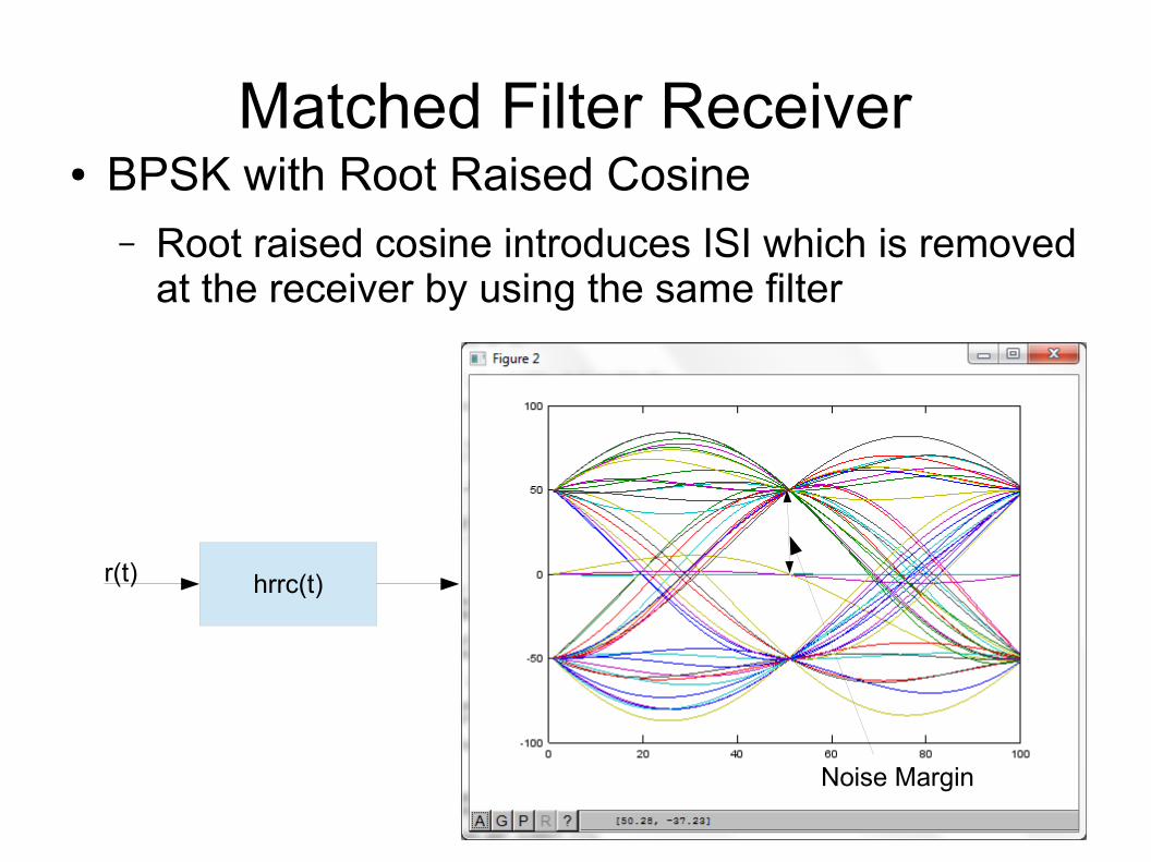
Matched Filter Receiver● BPSK with Root Raised Cosine
– Root raised cosine introduces ISI which is removed at the receiver by using the same filter
Noise Margin
hrrc(t)r(t)
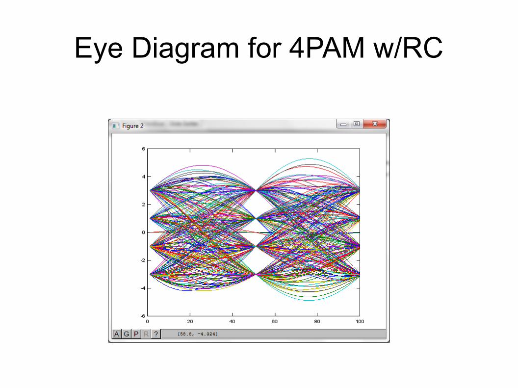
Eye Diagram for 4PAM w/RC
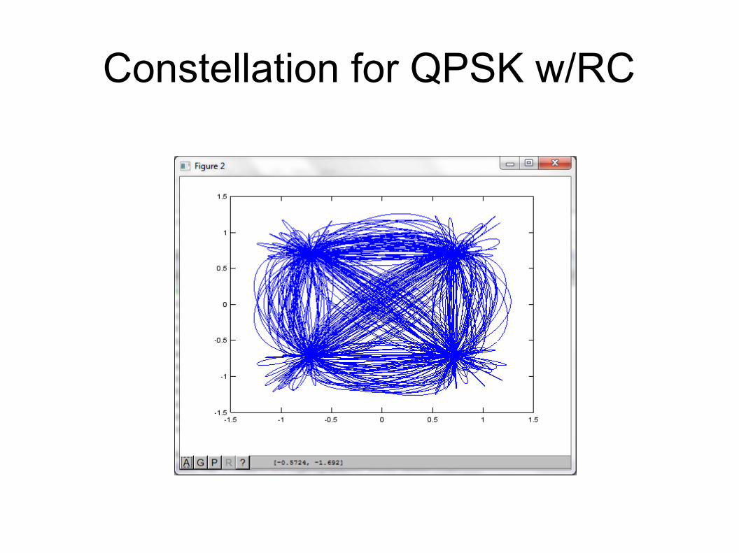
Constellation for QPSK w/RC
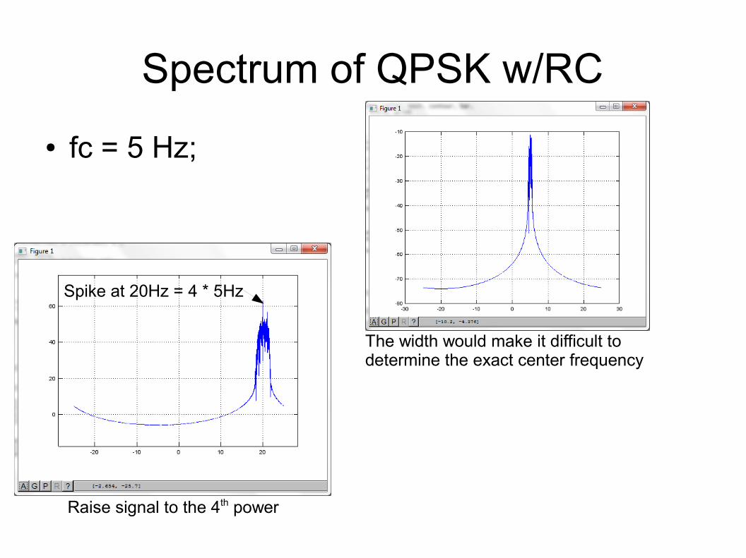
Spectrum of QPSK w/RC
● fc = 5 Hz;
The width would make it difficult to determine the exact center frequency
Raise signal to the 4th power
Spike at 20Hz = 4 * 5Hz
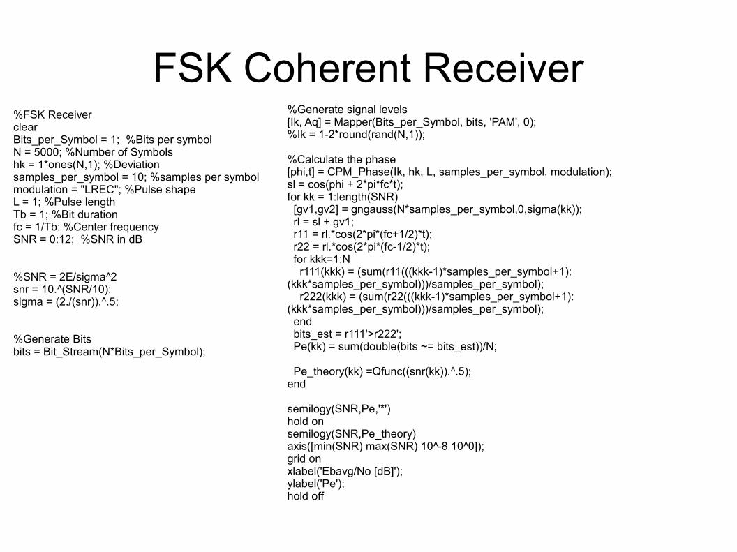
FSK Coherent Receiver%FSK ReceiverclearBits_per_Symbol = 1; %Bits per symbolN = 5000; %Number of Symbolshk = 1*ones(N,1); %Deviationsamples_per_symbol = 10; %samples per symbolmodulation = "LREC"; %Pulse shapeL = 1; %Pulse lengthTb = 1; %Bit durationfc = 1/Tb; %Center frequencySNR = 0:12; %SNR in dB
%SNR = 2E/sigma^2snr = 10.^(SNR/10);sigma = (2./(snr)).^.5;
%Generate Bitsbits = Bit_Stream(N*Bits_per_Symbol);
%Generate signal levels[Ik, Aq] = Mapper(Bits_per_Symbol, bits, 'PAM', 0);%Ik = 1-2*round(rand(N,1));
%Calculate the phase[phi,t] = CPM_Phase(Ik, hk, L, samples_per_symbol, modulation);sl = cos(phi + 2*pi*fc*t);for kk = 1:length(SNR) [gv1,gv2] = gngauss(N*samples_per_symbol,0,sigma(kk)); rl = sl + gv1; r11 = rl.*cos(2*pi*(fc+1/2)*t); r22 = rl.*cos(2*pi*(fc-1/2)*t); for kkk=1:N r111(kkk) = (sum(r11(((kkk-1)*samples_per_symbol+1):(kkk*samples_per_symbol)))/samples_per_symbol); r222(kkk) = (sum(r22(((kkk-1)*samples_per_symbol+1):(kkk*samples_per_symbol)))/samples_per_symbol); end bits_est = r111'>r222'; Pe(kk) = sum(double(bits ~= bits_est))/N; Pe_theory(kk) =Qfunc((snr(kk)).^.5);end
semilogy(SNR,Pe,'*')hold onsemilogy(SNR,Pe_theory)axis([min(SNR) max(SNR) 10^-8 10^0]);grid onxlabel('Ebavg/No [dB]');ylabel('Pe');hold off
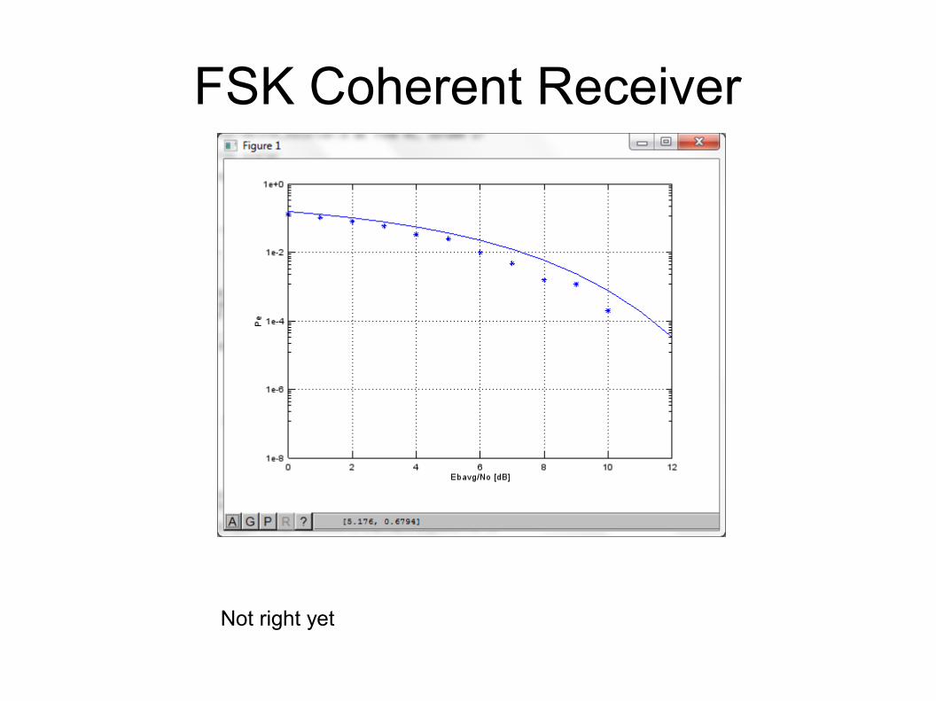
FSK Coherent Receiver
Not right yet
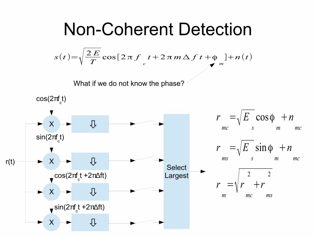
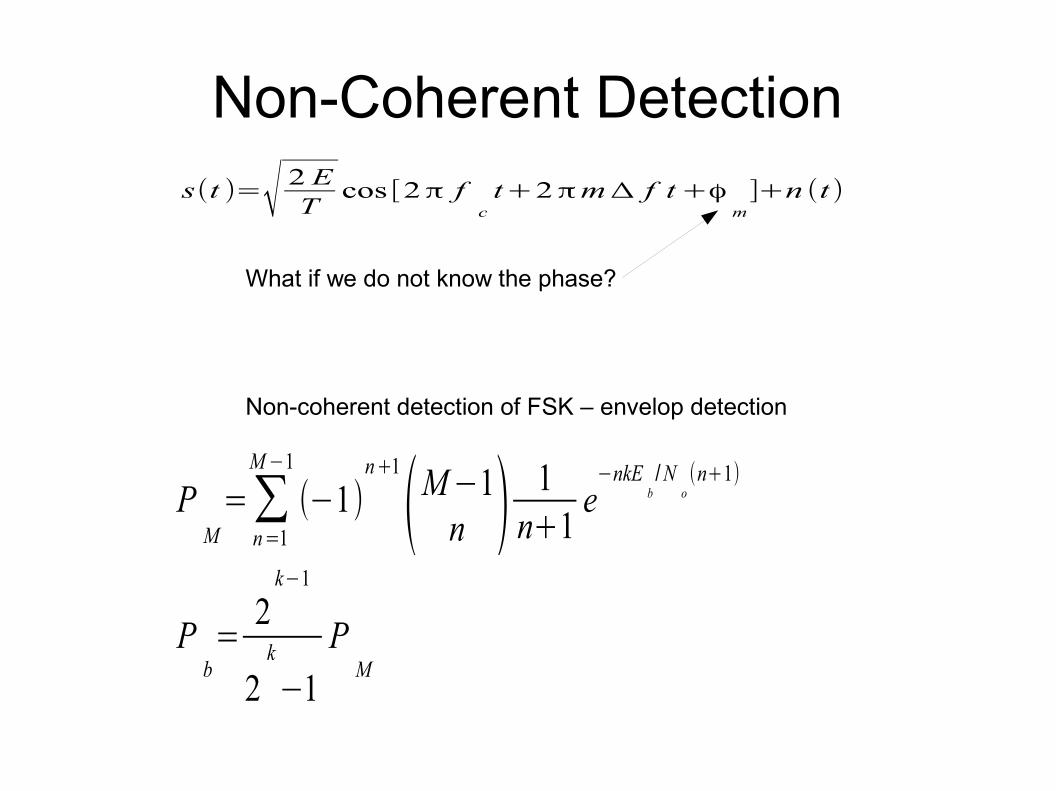
Non-Coherent Detections(t )=√ 2 E
Tcos [2π f
ct+2πmΔ f t+ϕ
m]+n (t)
What if we do not know the phase?
X
cos(2πfct)
X
X
SelectLargest
r(t)
sin(2πfct)
X
cos(2πfct +2π∆ft)
sin(2πfct +2π∆ft)
rmc
=√Escosϕ
m+n
mc
rms
=√Essinϕ
m+n
mc
rm=√r
mc
2
+rms
2
Non-Coherent Detections(t )=√ 2 E
Tcos [2π f
ct+2πmΔ f t+ϕ
m]+n (t)
What if we do not know the phase?
PM=∑
n=1
M −1
(−1)n+1
(M−1n ) 1
n+1e
−nkEb/N
o(n+1)
Non-coherent detection of FSK – envelop detection
Pb=
2k−1
2k
−1P
M
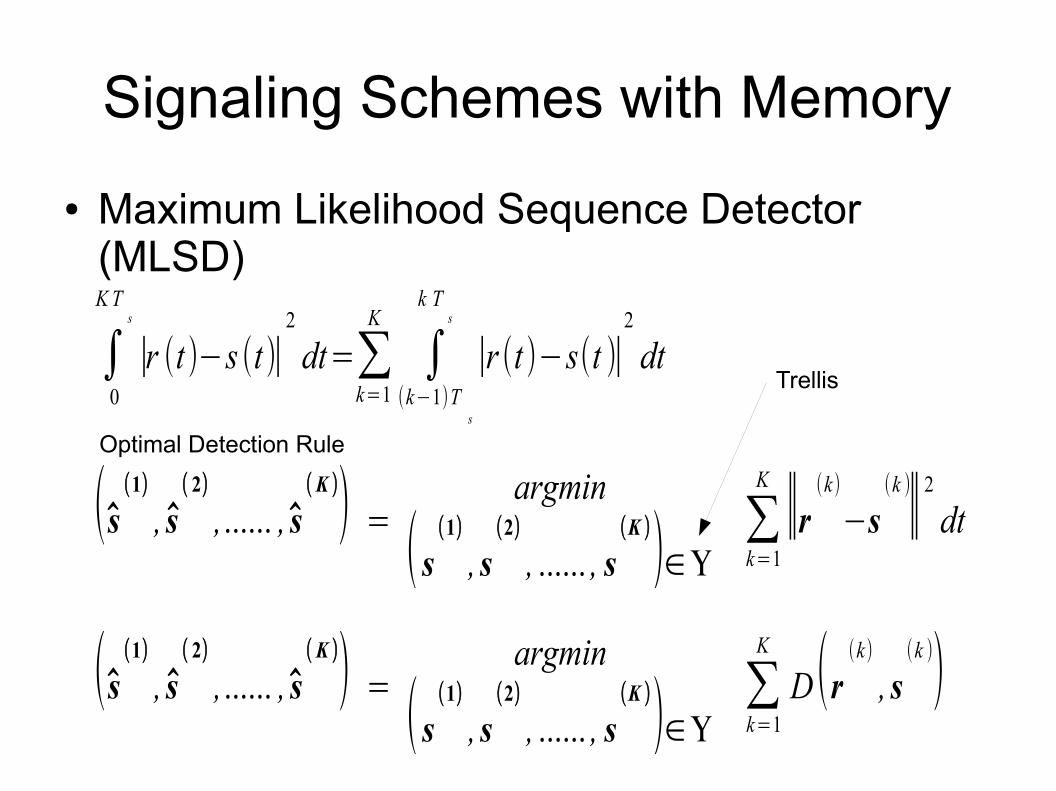
Signaling Schemes with Memory
● Maximum Likelihood Sequence Detector (MLSD)
∫0
KTs
∣r (t)−s (t)∣2
dt=∑k=1
K
∫(k−1)T
s
k Ts
∣r (t )−s(t )∣2
dt
Optimal Detection Rule
(s(1)
, s( 2)
,...... , s(K )) =
argmin
(s(1)
, s(2)
, ...... , s(K )
)∈Υ∑k=1
K
∣∣r(k)
−s(k )∣∣2
dt
(s(1)
, s( 2)
,...... , s(K )) =
argmin
(s(1)
, s(2)
, ...... , s(K )
)∈Υ∑k=1
K
D(r(k)
, s(k ))
Trellis
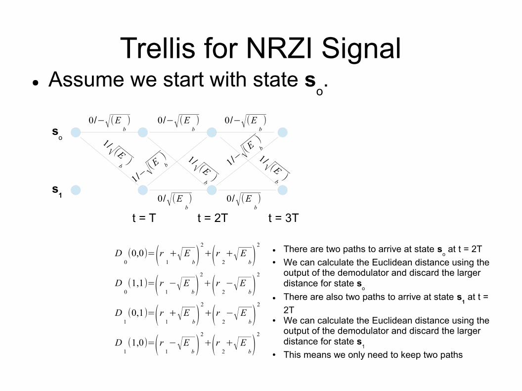
Trellis for NRZI Signal● Assume we start with state s
o.
0/−√(Eb)
so
s1
1/√ (Eb
) 1/√ (Eb
)
1/√ (Eb
)
0/−√(Eb)
0/√(Eb)
0/−√(Eb)
0/√(Eb)
1/− √(
E b
)1/− √(
E b
)
t = T t = 2T t = 3T
D0(0,0)=(r 1
+√Eb)
2
+(r 2+√E
b)2
D0(1,1)=(r 1
−√Eb)
2
+(r 2−√E
b)2
● There are two paths to arrive at state so at t = 2T
● We can calculate the Euclidean distance using the output of the demodulator and discard the larger distance for state s
o
● There are also two paths to arrive at state s1 at t =
2T● We can calculate the Euclidean distance using the
output of the demodulator and discard the larger distance for state s
1
● This means we only need to keep two paths
D1(0,1)=(r 1
+√Eb)
2
+(r 2−√E
b)2
D1(1,0)=(r 1
−√Eb )
2
+(r 2+√E
b)2
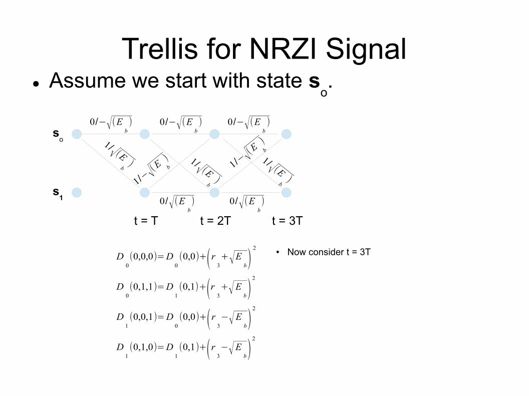
Trellis for NRZI Signal● Assume we start with state s
o.
D0(0,0,0)=D
0(0,0)+(r 3
+√Eb)
2
D0(0,1,1)=D
1(0,1)+(r 3
+√Eb)
2
● Now consider t = 3T
D1(0,0,1)=D
0(0,0)+(r 3
−√Eb)
2
D1(0,1,0)=D
1(0,1)+(r 3
−√Eb)
2
0/−√(Eb)
so
s1
1/√ (Eb
) 1/√ (Eb
)
1/√ (Eb
)
0/−√(Eb)
0/√(Eb)
0/−√(Eb)
0/√(Eb)
1/− √(
E b
)1/− √(
E b
)
t = T t = 2T t = 3T