elevator and escalator rescue training lesson 2008 … · - 2 - contents introduction 3 types of...
TRANSCRIPT
DALLAS FIRE-RESCUE
ELEVATOR and ESCALATOR RESCUE
TRAINING LESSON
2008
- 2 -
CONTENTS INTRODUCTION 3 TYPES OF ELEVATORS 4 COMPONENTS 8 RESCUE PROCEDURES 17
OTHER ELEVATOR EMERGENCIES 31 ESCALATORS 34 GLOSSARY 36
- 3 -
INTRODUCTION Although the concept of elevators transporting people is relatively simple, extrication of trapped occupants can often be difficult. Consider the following possible conditions:
• An elevator may have stopped between floors. • Loss of electrical power has resulted in a dark elevator with no ventilation. • Passengers may be hysterical, panicked, or in need of medical care.
These conditions are further complicated by the fact that elevator technology constantly changes. There are numerous elevator manufacturers, each having produced a variety of elevators. It is not uncommon for a single elevator to have features and special equipment offered by several manufacturers, resulting in a wide variety of elevators with unique characteristics. Elevator technology is constantly improving. The guidelines presented in this document are not intended to cover all problems that may be encountered – rather, they are provided in an effort to consider the more common ones, and to provide procedures for firefighters to utilize during elevator emergencies. The safety of firefighters and citizens should be at the forefront of any rescue operation. We are not elevator mechanics, but firefighters working in an open elevator shaft. Keep that philosophy in mind, and everyone should return home safely. Company officers are encouraged to get out into the district and review elevator components during inspections. Coordinate elevator operational visits with building maintenance or elevator service representatives. Identify Knox Box locations and what keys are available. Preplanning is the key.
- 4 -
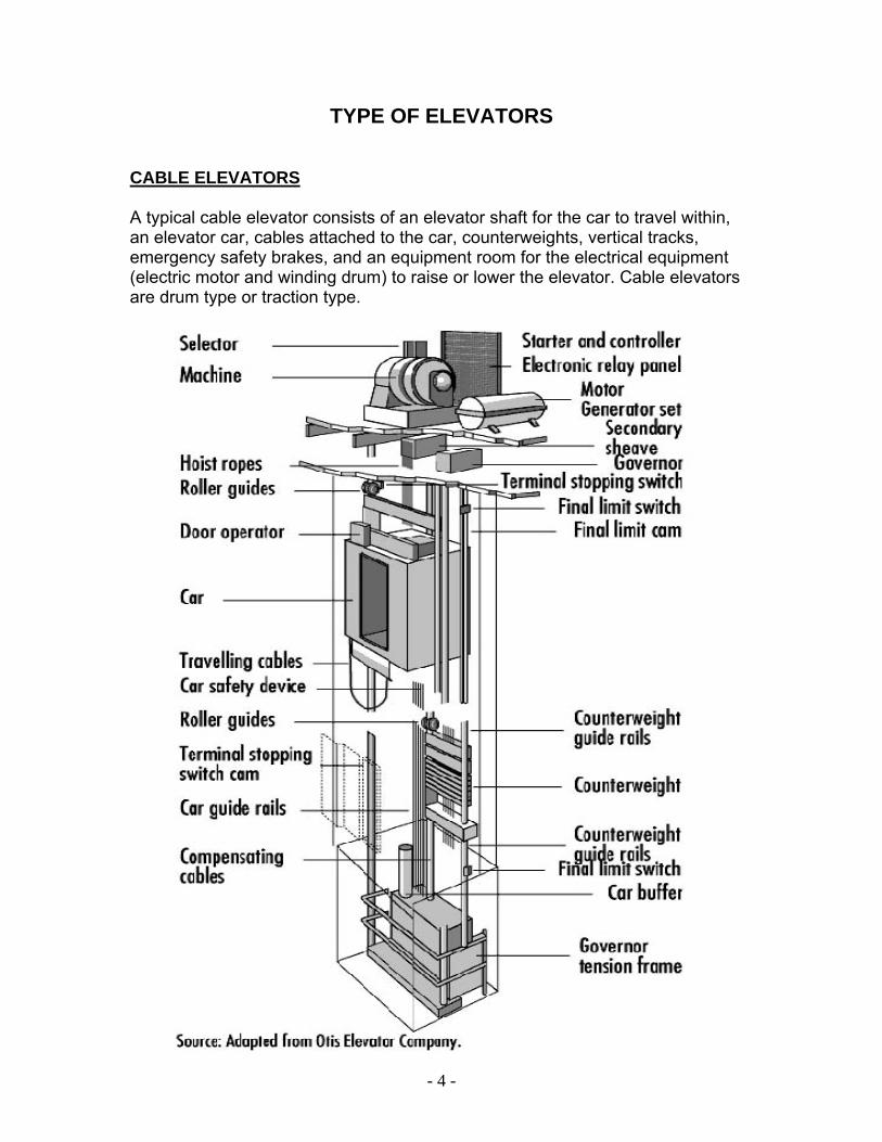
TYPE OF ELEVATORS CABLE ELEVATORS A typical cable elevator consists of an elevator shaft for the car to travel within, an elevator car, cables attached to the car, counterweights, vertical tracks, emergency safety brakes, and an equipment room for the electrical equipment (electric motor and winding drum) to raise or lower the elevator. Cable elevators are drum type or traction type.
- 5 -
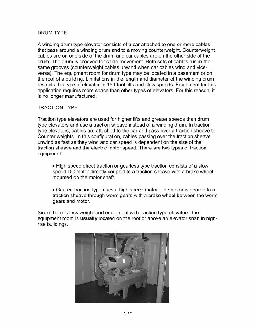
DRUM TYPE A winding drum type elevator consists of a car attached to one or more cables that pass around a winding drum and to a moving counterweight. Counterweight cables are on one side of the drum and car cables are on the other side of the drum. The drum is grooved for cable movement. Both sets of cables run in the same grooves (counterweight cables unwind when car cables wind and vice-versa). The equipment room for drum type may be located in a basement or on the roof of a building. Limitations in the length and diameter of the winding drum restricts this type of elevator to 150-foot lifts and slow speeds. Equipment for this application requires more space than other types of elevators. For this reason, it is no longer manufactured. TRACTION TYPE Traction type elevators are used for higher lifts and greater speeds than drum type elevators and use a traction sheave instead of a winding drum. In traction type elevators, cables are attached to the car and pass over a traction sheave to Counter weights. In this configuration, cables passing over the traction sheave unwind as fast as they wind and car speed is dependent on the size of the traction sheave and the electric motor speed. There are two types of traction equipment:
• High speed direct traction or gearless type traction consists of a slow speed DC motor directly coupled to a traction sheave with a brake wheel mounted on the motor shaft. • Geared traction type uses a high speed motor. The motor is geared to a traction sheave through worm gears with a brake wheel between the worm gears and motor.
Since there is less weight and equipment with traction type elevators, the equipment room is usually located on the roof or above an elevator shaft in high-rise buildings.
- 6 -
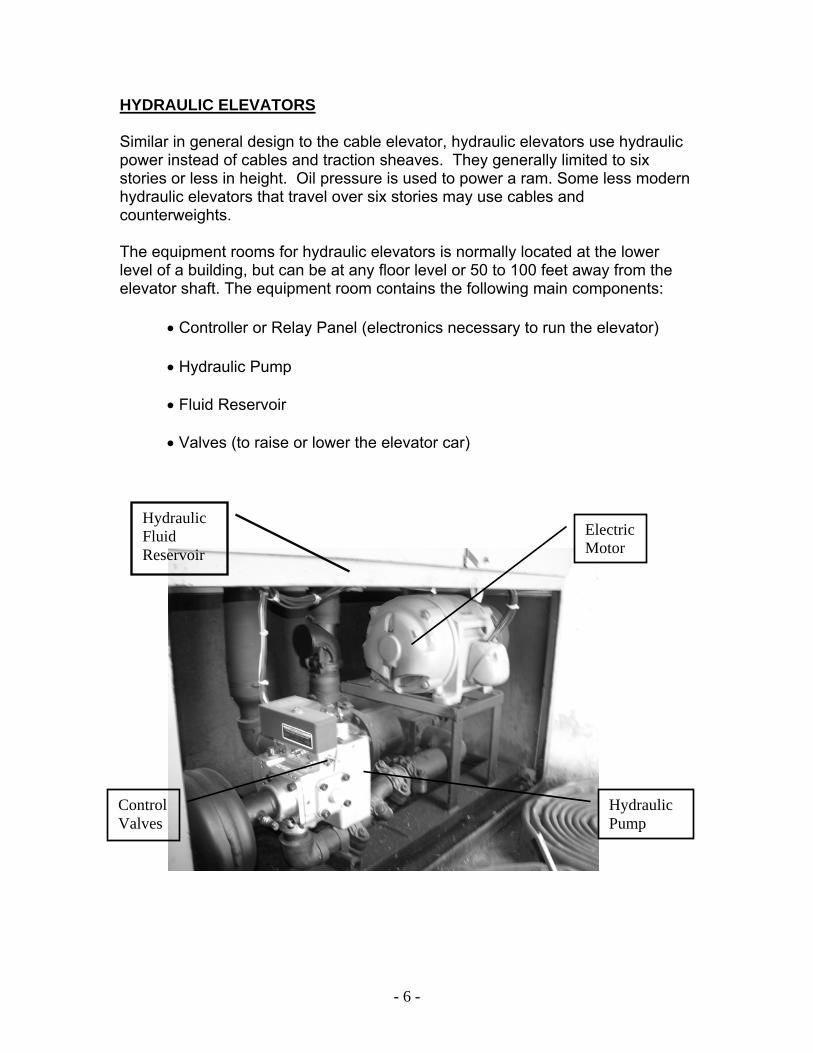
HYDRAULIC ELEVATORS Similar in general design to the cable elevator, hydraulic elevators use hydraulic power instead of cables and traction sheaves. They generally limited to six stories or less in height. Oil pressure is used to power a ram. Some less modern hydraulic elevators that travel over six stories may use cables and counterweights. The equipment rooms for hydraulic elevators is normally located at the lower level of a building, but can be at any floor level or 50 to 100 feet away from the elevator shaft. The equipment room contains the following main components:
• Controller or Relay Panel (electronics necessary to run the elevator) • Hydraulic Pump • Fluid Reservoir • Valves (to raise or lower the elevator car)
Control Valves
Hydraulic Pump
Electric Motor
Hydraulic Fluid Reservoir
- 7 -
The hydraulic fluid supply tank can contain 200 – 1000 gallons of combustible hydraulic fluid. The submersible pump located in some hydraulic tanks can malfunction and the fluid can become overheated to the point of generating smoke. This can become a source of fire alarm activations in buildings. Keep in mind that a hydraulic elevator can still move if there is a leak in the hydraulic system. During prolonged operations, it may become necessary to shut-off of the hydraulic valves in addition to removing the power to the unit. PASSENGER ELEVATORS Passenger elevators (cable and hydraulic) are designed to quickly move passengers to different levels within a multi-story building. Modern passenger elevators are completely automated and are under the control of an electronic computer which constantly evaluates the needs and demands of the system. Computers constantly make adjustments, move cars, and work to meet current demands. Cars are sent to the area of greatest need and when cars are not needed, they are allowed to rest or sleep. Passenger elevators are normally faster than freight elevators and often use express elevators that can not stop at all floors. FREIGHT ELEVATORS Freight elevators (cable and hydraulic) are generally less complicated and serve a different purpose than passenger elevators. Larger than passenger elevators, freight elevators can be as large as 12 feet by 14 feet and have a carrying capacity of up to three tons. Generally, freight elevators are separate from the main lobby of a building and can have a street, alley, or loading dock access. Not being under computer control, freight elevators are simpler to operate and control than passenger elevators. They normally service an entire building from the lowest to highest level. Freight elevators are normally slower than passenger elevators and can stop at all floors unless a special override control is activated.
MACHINE ROOM-LESS ELEVATORS
The newest member of the elevator family is the Machine Room-Less Elevators (MRL). In MRL elevators the mechanical drive equipment is located within the hoistway walls. Many of these systems utilize high-tensile strength steel-corded drive belts for traction, rather than the traditional steel hoist ropes. When these systems are encountered, having a qualified elevator mechanic on-scene is an invaluable resource during a detailed rescue operation.
- 8 -
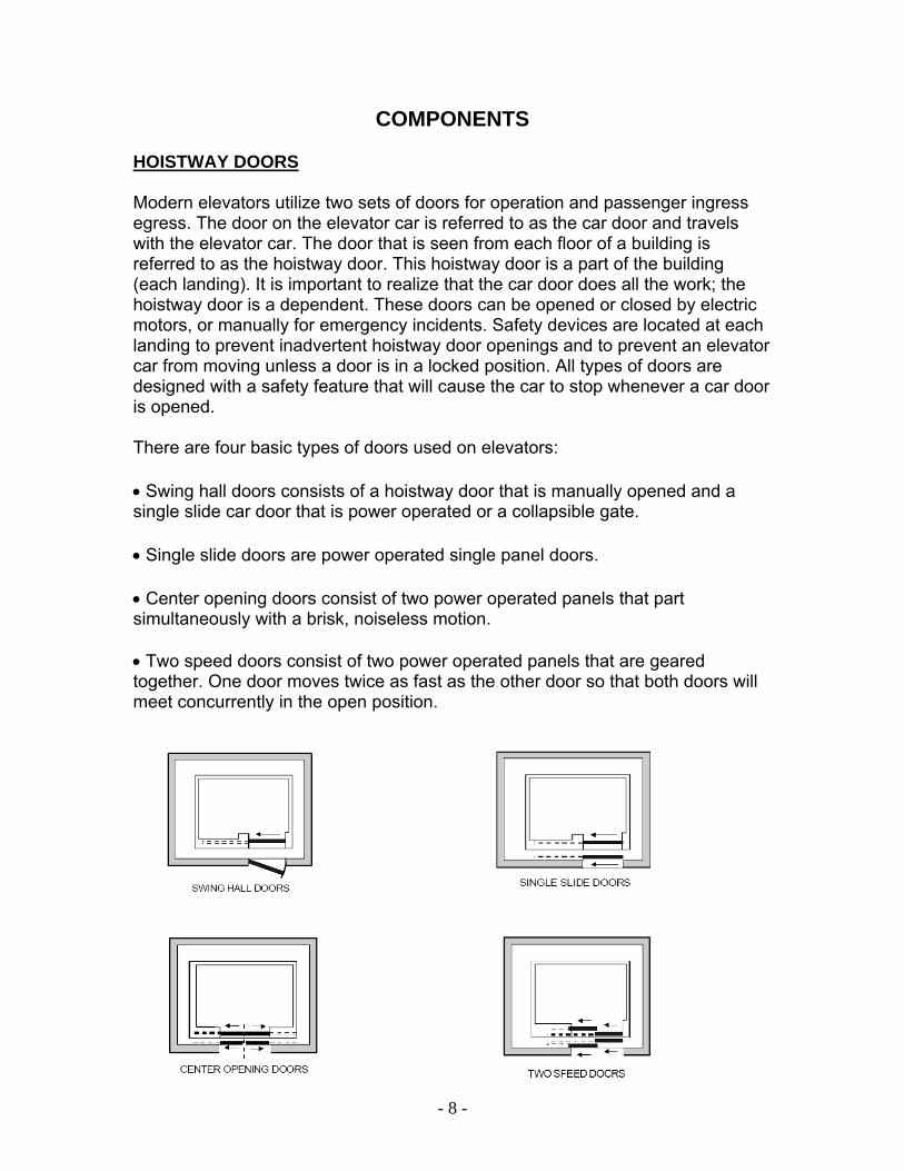
COMPONENTS HOISTWAY DOORS Modern elevators utilize two sets of doors for operation and passenger ingress egress. The door on the elevator car is referred to as the car door and travels with the elevator car. The door that is seen from each floor of a building is referred to as the hoistway door. This hoistway door is a part of the building (each landing). It is important to realize that the car door does all the work; the hoistway door is a dependent. These doors can be opened or closed by electric motors, or manually for emergency incidents. Safety devices are located at each landing to prevent inadvertent hoistway door openings and to prevent an elevator car from moving unless a door is in a locked position. All types of doors are designed with a safety feature that will cause the car to stop whenever a car door is opened. There are four basic types of doors used on elevators: • Swing hall doors consists of a hoistway door that is manually opened and a single slide car door that is power operated or a collapsible gate. • Single slide doors are power operated single panel doors. • Center opening doors consist of two power operated panels that part simultaneously with a brisk, noiseless motion. • Two speed doors consist of two power operated panels that are geared together. One door moves twice as fast as the other door so that both doors will meet concurrently in the open position.
- 9 -
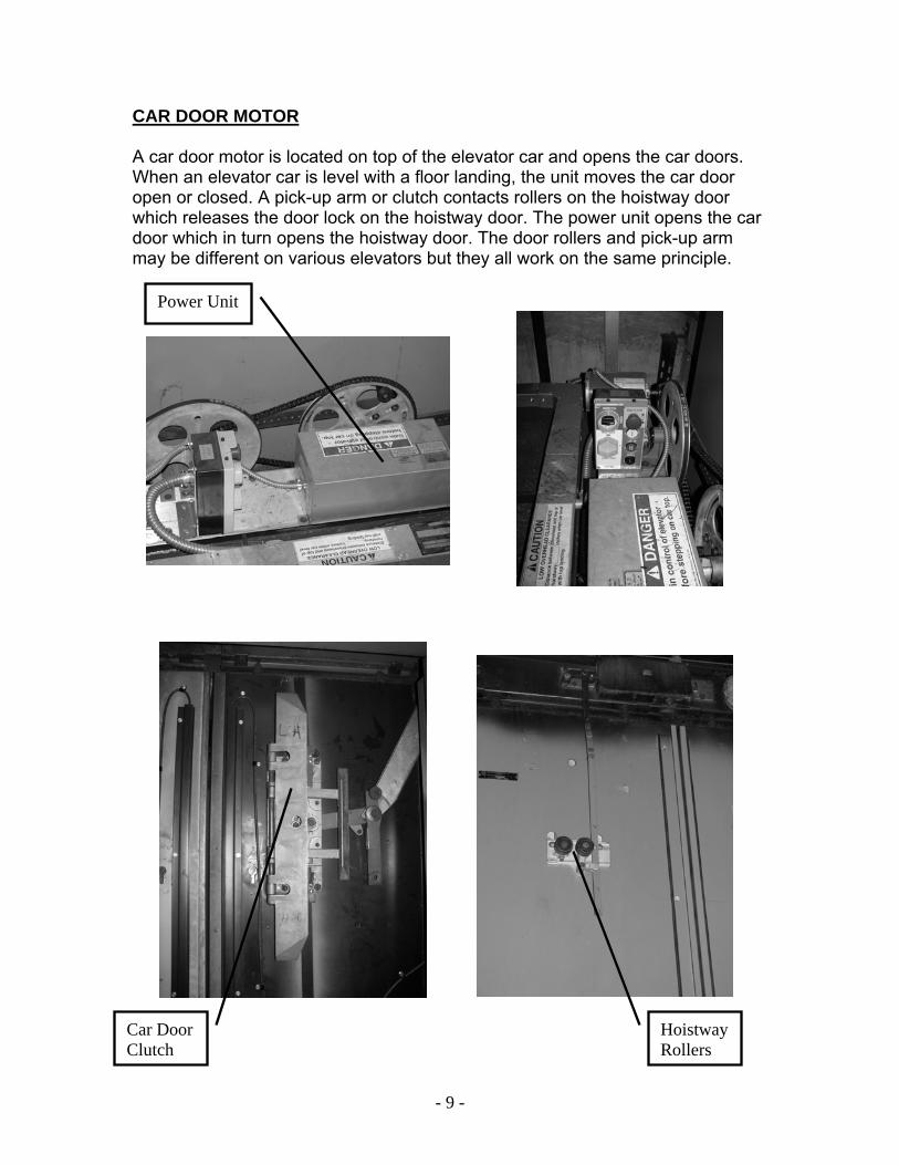
CAR DOOR MOTOR A car door motor is located on top of the elevator car and opens the car doors. When an elevator car is level with a floor landing, the unit moves the car door open or closed. A pick-up arm or clutch contacts rollers on the hoistway door which releases the door lock on the hoistway door. The power unit opens the car door which in turn opens the hoistway door. The door rollers and pick-up arm may be different on various elevators but they all work on the same principle.
Power Unit
Hoistway Rollers
Car Door Clutch
- 10 -
HOISTWAY DOOR LOCKS Hoistway doors are equipped with a locking mechanism to prevent the opening of a door and exposure to a open shaft. When the elevator car is within 18 inches of the landing a clutch on the back of the car door contacts rollers on the hoistway door. This releases the hoistway door lock on top of the door. When the car door motor activates the doors the clutch freely grabs and moves the
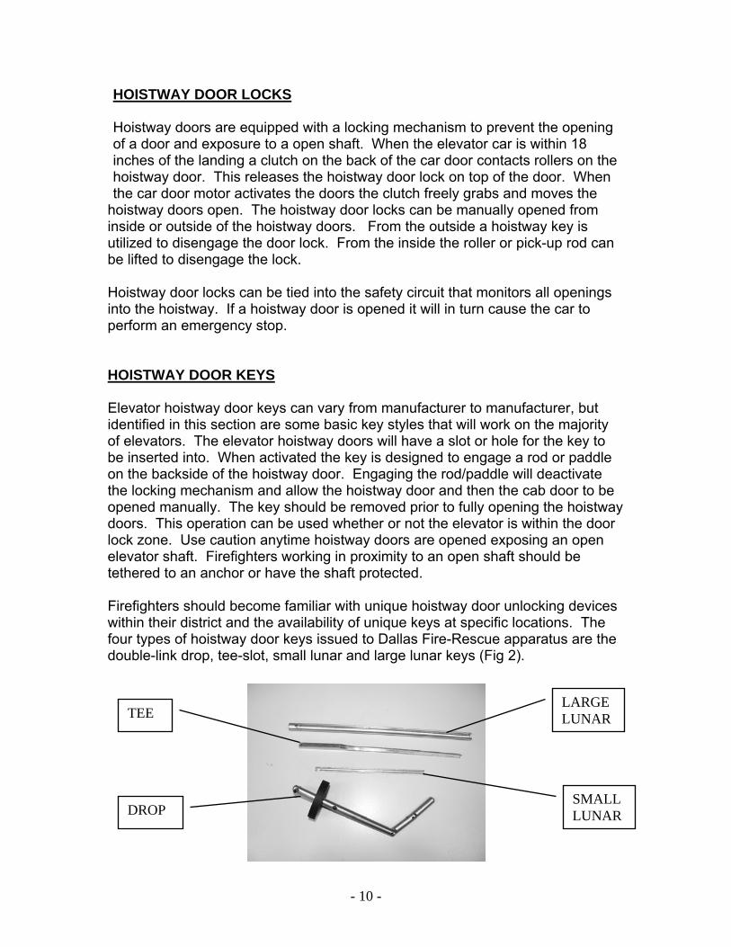
hoistway doors open. The hoistway door locks can be manually opened from inside or outside of the hoistway doors. From the outside a hoistway key is utilized to disengage the door lock. From the inside the roller or pick-up rod can be lifted to disengage the lock. Hoistway door locks can be tied into the safety circuit that monitors all openings into the hoistway. If a hoistway door is opened it will in turn cause the car to perform an emergency stop. HOISTWAY DOOR KEYS Elevator hoistway door keys can vary from manufacturer to manufacturer, but identified in this section are some basic key styles that will work on the majority of elevators. The elevator hoistway doors will have a slot or hole for the key to be inserted into. When activated the key is designed to engage a rod or paddle on the backside of the hoistway door. Engaging the rod/paddle will deactivate the locking mechanism and allow the hoistway door and then the cab door to be opened manually. The key should be removed prior to fully opening the hoistway doors. This operation can be used whether or not the elevator is within the door lock zone. Use caution anytime hoistway doors are opened exposing an open elevator shaft. Firefighters working in proximity to an open shaft should be tethered to an anchor or have the shaft protected. Firefighters should become familiar with unique hoistway door unlocking devices within their district and the availability of unique keys at specific locations. The four types of hoistway door keys issued to Dallas Fire-Rescue apparatus are the double-link drop, tee-slot, small lunar and large lunar keys (Fig 2).
Car Door Clutch
TEE
DROP SMALL LUNAR
LARGE LUNAR
- 11 -
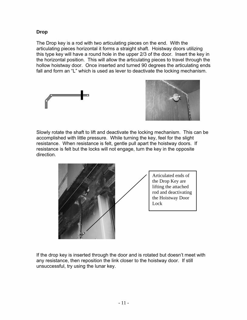
Drop The Drop key is a rod with two articulating pieces on the end. With the articulating pieces horizontal it forms a straight shaft. Hoistway doors utilizing this type key will have a round hole in the upper 2/3 of the door. Insert the key in the horizontal position. This will allow the articulating pieces to travel through the hollow hoistway door. Once inserted and turned 90 degrees the articulating ends fall and form an “L” which is used as lever to deactivate the locking mechanism.
Slowly rotate the shaft to lift and deactivate the locking mechanism. This can be accomplished with little pressure. While turning the key, feel for the slight resistance. When resistance is felt, gentle pull apart the hoistway doors. If resistance is felt but the locks will not engage, turn the key in the opposite direction. If the drop key is inserted through the door and is rotated but doesn’t meet with any resistance, then reposition the link closer to the hoistway door. If still unsuccessful, try using the lunar key.
Articulated ends of the Drop Key are lifting the attached rod and deactivating the Hoistway Door Lock
- 12 -
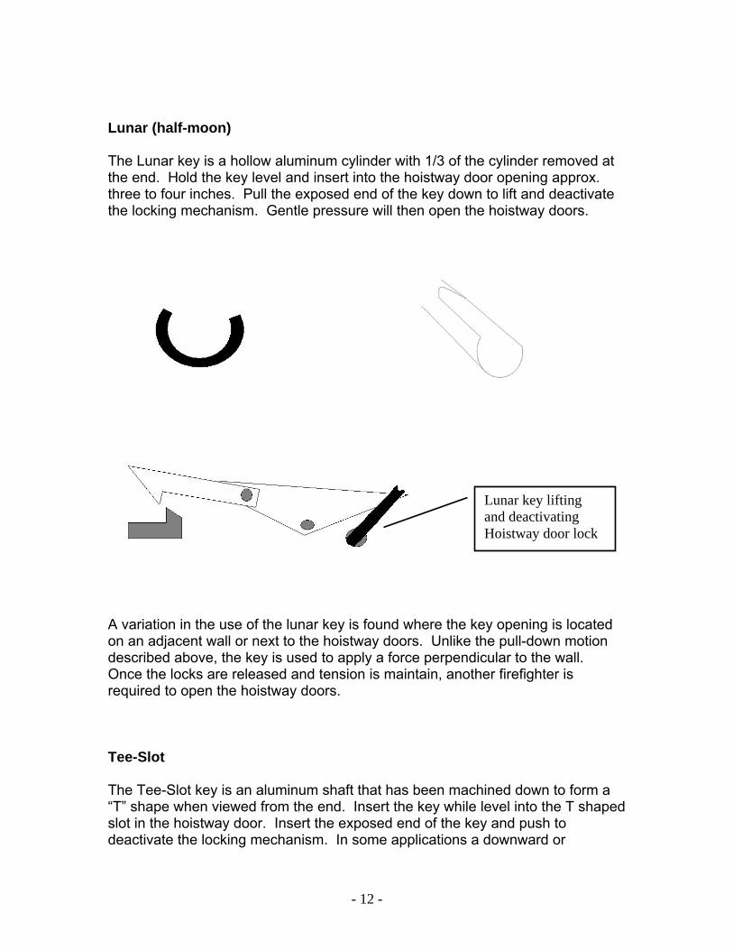
Lunar (half-moon) The Lunar key is a hollow aluminum cylinder with 1/3 of the cylinder removed at the end. Hold the key level and insert into the hoistway door opening approx. three to four inches. Pull the exposed end of the key down to lift and deactivate the locking mechanism. Gentle pressure will then open the hoistway doors. A variation in the use of the lunar key is found where the key opening is located on an adjacent wall or next to the hoistway doors. Unlike the pull-down motion described above, the key is used to apply a force perpendicular to the wall. Once the locks are released and tension is maintain, another firefighter is required to open the hoistway doors. Tee-Slot The Tee-Slot key is an aluminum shaft that has been machined down to form a “T” shape when viewed from the end. Insert the key while level into the T shaped slot in the hoistway door. Insert the exposed end of the key and push to deactivate the locking mechanism. In some applications a downward or
Lunar key lifting and deactivating Hoistway door lock

- 13 -
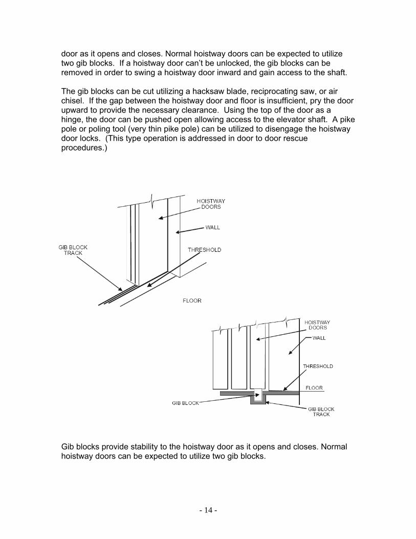
sideward motion may be required to unlock the doors. Gentle pressure will open the hoistway doors. Officers are advised to maintain elevator rescue tools in a common and accessible location. Hoistway door keys can be attached to a ring and clip, or maintained in an “elevator rescue” tool kit. Either will ensure keys are kept together and provide a means to secure the keys once the doors are opened. GIB BLOCKS The top of all modern elevator hoistway doors hang on rollers and the bottom is equipped with gib blocks. Gib blocks are made of various plastic materials and are approximately 3” wide X 1”high X ½” thick. Hoistway doors generally have blocks every 18-inches across the underside of the door panel. They ride in tracks that are in the floor landing. Gib blocks provide stability to the hoistway
- 14 -
door as it opens and closes. Normal hoistway doors can be expected to utilize two gib blocks. If a hoistway door can’t be unlocked, the gib blocks can be removed in order to swing a hoistway door inward and gain access to the shaft. The gib blocks can be cut utilizing a hacksaw blade, reciprocating saw, or air chisel. If the gap between the hoistway door and floor is insufficient, pry the door upward to provide the necessary clearance. Using the top of the door as a hinge, the door can be pushed open allowing access to the elevator shaft. A pike pole or poling tool (very thin pike pole) can be utilized to disengage the hoistway door locks. (This type operation is addressed in door to door rescue procedures.) Gib blocks provide stability to the hoistway door as it opens and closes. Normal hoistway doors can be expected to utilize two gib blocks.
- 15 -
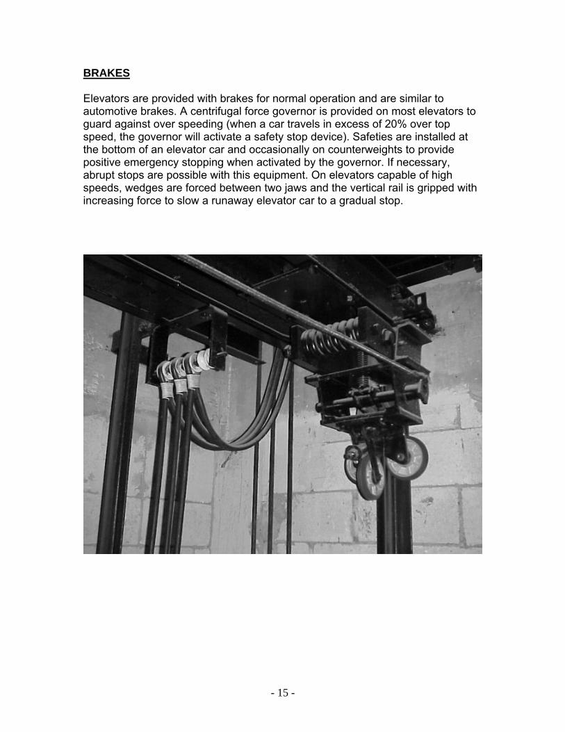
BRAKES Elevators are provided with brakes for normal operation and are similar to automotive brakes. A centrifugal force governor is provided on most elevators to guard against over speeding (when a car travels in excess of 20% over top speed, the governor will activate a safety stop device). Safeties are installed at the bottom of an elevator car and occasionally on counterweights to provide positive emergency stopping when activated by the governor. If necessary, abrupt stops are possible with this equipment. On elevators capable of high speeds, wedges are forced between two jaws and the vertical rail is gripped with increasing force to slow a runaway elevator car to a gradual stop.
- 16 -
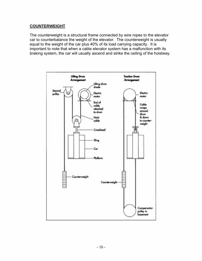
COUNTERWEIGHT The counterweight is a structural frame connected by wire ropes to the elevator car to counterbalance the weight of the elevator. The counterweight is usually equal to the weight of the car plus 40% of its load carrying capacity. It is important to note that when a cable elevator system has a malfunction with its braking system, the car will usually ascend and strike the ceiling of the hoistway.
- 17 -
RESCUE PROCEDURES Prior to initiating elevator rescue procedures, dispatch and on scene information should be carefully evaluated. When an alarm is received, knowledge of the type and height of occupancies in the geographical area of dispatch will indicate the probable type of elevator (hydraulic or cable), applications (industrial-commercial, apartments, multi-story office buildings, high rise, etc.), and the time of day (indicator of the potential of trapped victims). When dispatched to an elevator rescue the following equipment should be carried into the structure by the first arriving company: Hoistway Door Keys Portable Radios PPE Coat, Helmet, & Gloves Halligan Tool & Axe Flashlights Short / Folding Ladder Knox Key Rabbit Tool Life Rope Bag On scene information should consist of the following minimum considerations:
• Is there an inoperative elevator?
• Does the inoperative elevator contain trapped occupant(s) and what is the occupant(s) condition?
• Has an elevator repair person been notified, and if so, what is their
estimated time of arrival? The occupants are only “locked in a box” and are safe unless we endanger them. Based on the conditions and the mechanics ETA waiting on the mechanic may be the best course of action.
• What is the location of the inoperative elevator? (Between floors or at a
landing) contact the security desk or observe lobby panel to assist in locating elevators.
• What is the type of elevator? (hydraulic or cable) (passenger of freight)
• Where is the elevator equipment room? (normally, above for a cable
elevator and below for a hydraulic elevator)
- 18 -
Once on scene there are guidelines for rescue to be considered. Remember the hazard control sequence: anticipate, identify, evaluate, alert, mitigate, and monitor. Various safe operations can be utilized to remove trapped passengers from an inoperative elevator. Use of a particular operation should be based on the safety of the operation, condition of the trapped occupants, and the expertise of the personnel. Elevator rescues should progress from simply resetting the power to more complex operations.
1) Resetting Electrical Power 2) Fire service Recall (Phase 1) 3) Utilizing Hoistway Door Key 4) Forcing Hoistway Doors 5) Moving an Elevator 6) Rope Rescue 7) Breaching Elevator Shafts
GENERAL GUIDELINES FOR RESCUES When it has been determined there is an inoperative elevator with trapped occupants, the following considerations should be initially implemented:
Position firefighters equipped with portable radios in the elevator equipment room and on the closest landing outside the inoperable elevator.
Elevator equipment room objectives:
•Obtain access to main power switches and elevator equipment. Firefighters in equipment room should check the electrical circuits (main switch, fuses, etc.) to verify if power is on or off to the elevator. •Occasionally, circuits are tripped due to overheating and can be safely reset. Coordinate with firefighters on landing prior to resetting any electrical equipment.

- 19 -
•Try to identify electrical shutoffs for cars in multiple elevator banks by car or shaft number. •If a 110 circuit can be identified for the lights and fan in the elevator; notify the incident commander. In some circumstances, it would be advantageous to leave these circuits on and shut down only the drive circuits. The occupants are already trapped in a stranded elevator car and removing the lighting and ventilation will not improve their situation. Safety of the operation will be the deciding factor regarding electrical power. •Once electrical power has been shut-down; a firefighter with radio is required to maintain control of the power during the rescue operation. If power is returned by other employees or mechanics it will jeopardize the safety of the operation. •Remember there may be up to 600 volts AC in an elevator machine room. Observe warning signs and leave forcible entry tools outside the door.
Outside inoperative elevator objectives: (elevator rescue procedures will be coordinated from this location).
• Establish voice contact with the trapped elevator victims and determine if they are in need of medical assistance, or if conditions are stable. If conditions are stable, inform the passengers they are safe and will be removed from the inoperative elevator in a short period of time. It is also advantageous to keep trapped passengers informed of operations that are being utilized to remove them. If in need of assistance determine condition of victims and what assistance will be needed. Call for Rescue to stand-by if medical needs are in question.
• Have the trapped passengers verify the status of the Emergency Stop Button. Remember that if an elevator is stalled due to a malfunction, (one that can be quickly corrected, i.e. overheated relay, loss of power from an activated main switch, etc.), it is necessary for the Emergency Stop Button to be disengaged before power will be returned to an inoperative elevator, (placed in the normal/run position.)
• Instruct the passengers to push the Door Open Button (if so equipped) and slightly wiggle the car door.
- 20 -
• If the elevator car is within a few inches of the landing floor, and the power is off in the equipment room, instruct the passengers to try to manually open the car door. This may require some effort as the car door operates the hoistway door through a clutch mechanism. Moving the car door will release the latch on the hoistway door and allow the door to be opened.
• If there is power to the elevator, coordinate turning the power off for at least 30 seconds and then back on again. This can reactivate the elevator by allowing relays to reset (at least 30 seconds is necessary to clear any previous programming in the elevator computer). If the elevator car is within a few inches of the landing, the door may be opened. Anytime firefighters have opened a hoistway door and operating around an open shaft, firefighters will be tethered to an anchor utilizing ropes or the opening will be protected by utilizing a short ladder for a rail.
NOTE: DO NOT attempt to rescue trapped passengers from an inoperative elevator unless the power to the elevator has been disconnected. This requires that a person be assigned to the main power switch until the rescue is completed. RESETTING ELECTRICAL POWER If there is power to the elevator, coordinate turning the power off for at least 30 seconds and then back on again. This can reactivate the elevator by allowing relays to reset (at least 30 seconds is necessary to clear any previous programming in the elevator computer).
•Advise victims in elevator that power is going to be temporarily disconnected to reset the system.
•Control room crew will coordinate the resetting the power with firefighters outside the stalled elevator. Be prepared that if the elevator car is within a few inches of the landing, the door may open when the system restarts.

- 21 -
FIRE SERVICE RECALL To place an elevator in “Recall” or Phase 1 mode, you will need the elevator control key. Depending on the occupancy the structure may or may not be required to have this key available within a Knox Box. A Knox Box is required in high-rise structures in accordance with the City of Dallas Fire Code, Section 10.302. The box should contain enough fire service keys to operate each elevator. There is no standard fire service control key. The type and style can vary for each manufacturer, but the control panel function and design is regulated by the State of Texas. During pre-fire planning, T.I.S., and occupancy inspections elevator service key information should be noted. Refer to departmental T.I.S. manual or contact FPE&I for guidance if the key requirements and application are in question. If a fire service elevator control key is available, insert the key into the lobby key switch. The lobby control switch is a three-position switch provided at the main floor and labeled “OFF”, “BYPASS”, and “ON”. When the key is turned to the “ON” position, all cars must return to the main floor and “park” with the doors open. Elevators without a landing at the main floor must return to the landing closest to the main floor or other approved landing. If a hoistway door lock has not been securely latched, the elevator control panel will stop the car. Activation of the Phase 1 recall will also override these safety switches and lower the car. Once the car has arrived at the main floor, the occupants can simply evacuate the elevator. The power to the elevator should be shut-off and the fire service switch returned to the “OFF” position. The “BYPASS” position is used to override any automated recall resulting from a fire alarm or smoke sensor. If equipped with a Phase 2 system, the fire service key can be removed and utilized inside the car. All switches for Phase 1 and Phase 2 operation are keyed alike. Insert the key into the fire service switch inside the car and the elevator can be manually operated. The car switch will be labeled “ON”, “OFF”, and “HOLD” (Some older elevators will have “BYPASS” instead of “HOLD”). In the “ON” position the car is under the sole control of the firefighter inside the car. Operational instructions should be located adjacent to the switch. In the “OFF” position the system is under normal operation and the “HOLD” position will cause the car to hold at its current location. State guidelines and addition information on elevator Phase 1 & Phase 2 operations can be found in the American Society of Mechanical Engineers publication A17.2-2007. If the determination is made to utilize an adjacent car for rescue, USAR should be requested to assist. During an adjacent car rescue, rescuers and victims are exposed to open elevator shafts and appropriate precautions should be maintained.
- 22 -
UTILIZING HOISTWAY DOOR CAR DOOR TO HOISTWAY DOOR RESCUE Door to door is the most frequently utilized and preferred form of manual elevator rescue. If the cab is within 18” of the floor landing and the power is disconnected it provides for a very safe and stable form of removal. Disengaging the locking mechanism can open the hoistway doors and provide access to the inoperative car.
1. Determine type of hoistway key needed (Drop, Lunar, and Tee). Look for a Knox Box adjacent to the elevator doors in the main lobby. The Knox Box may contain additional keys and access to the elevator room. 2. If equipped, instruct victims to engage “Elevator Stop Button” in car. 3. Confirm equipment room crew has disconnected elevator power supply. 4. Ensure crew members operating around any open shaft are tethered to an anchor or the shaft is protected. 5. Open hoistway doors using doors keys. 6. Car doors will freely move if within operational range of floor (18”). If separation is greater than 18”, car door will need to be disengaged. Locate the car door disengagement lever and activate. Once the lever is activated the car doors will freely move. 7. Protect victims from any open elevator shaft and remove them from elevator. 8. Close and secure cab & hoistway doors. 9. Place elevator out-of-service and notify building representative.
CEILING EXIT TO HOISTWAY DOOR If the hoistway door on a floor can’t be utilized, access can be obtained from the floor above. For this type of rescue the car must be equipped with a ceiling exit hatch. Cars in Observation or open elevator shafts will not have this feature. It should also be noted that this type of removal will be difficult for large or non-ambulatory victims. Prior to this operation it must be determined if the car is in danger of being overloaded. An elevator and brake system is designed to
- 23 -
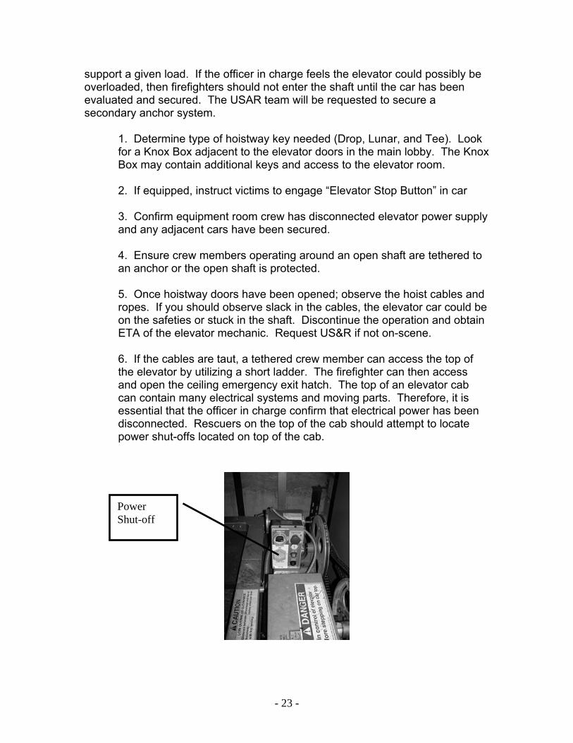
Power Shut-off
support a given load. If the officer in charge feels the elevator could possibly be overloaded, then firefighters should not enter the shaft until the car has been evaluated and secured. The USAR team will be requested to secure a secondary anchor system.
1. Determine type of hoistway key needed (Drop, Lunar, and Tee). Look for a Knox Box adjacent to the elevator doors in the main lobby. The Knox Box may contain additional keys and access to the elevator room. 2. If equipped, instruct victims to engage “Elevator Stop Button” in car 3. Confirm equipment room crew has disconnected elevator power supply and any adjacent cars have been secured. 4. Ensure crew members operating around an open shaft are tethered to an anchor or the open shaft is protected. 5. Once hoistway doors have been opened; observe the hoist cables and ropes. If you should observe slack in the cables, the elevator car could be on the safeties or stuck in the shaft. Discontinue the operation and obtain ETA of the elevator mechanic. Request US&R if not on-scene. 6. If the cables are taut, a tethered crew member can access the top of the elevator by utilizing a short ladder. The firefighter can then access and open the ceiling emergency exit hatch. The top of an elevator cab can contain many electrical systems and moving parts. Therefore, it is essential that the officer in charge confirm that electrical power has been disconnected. Rescuers on the top of the cab should attempt to locate power shut-offs located on top of the cab.
- 24 -
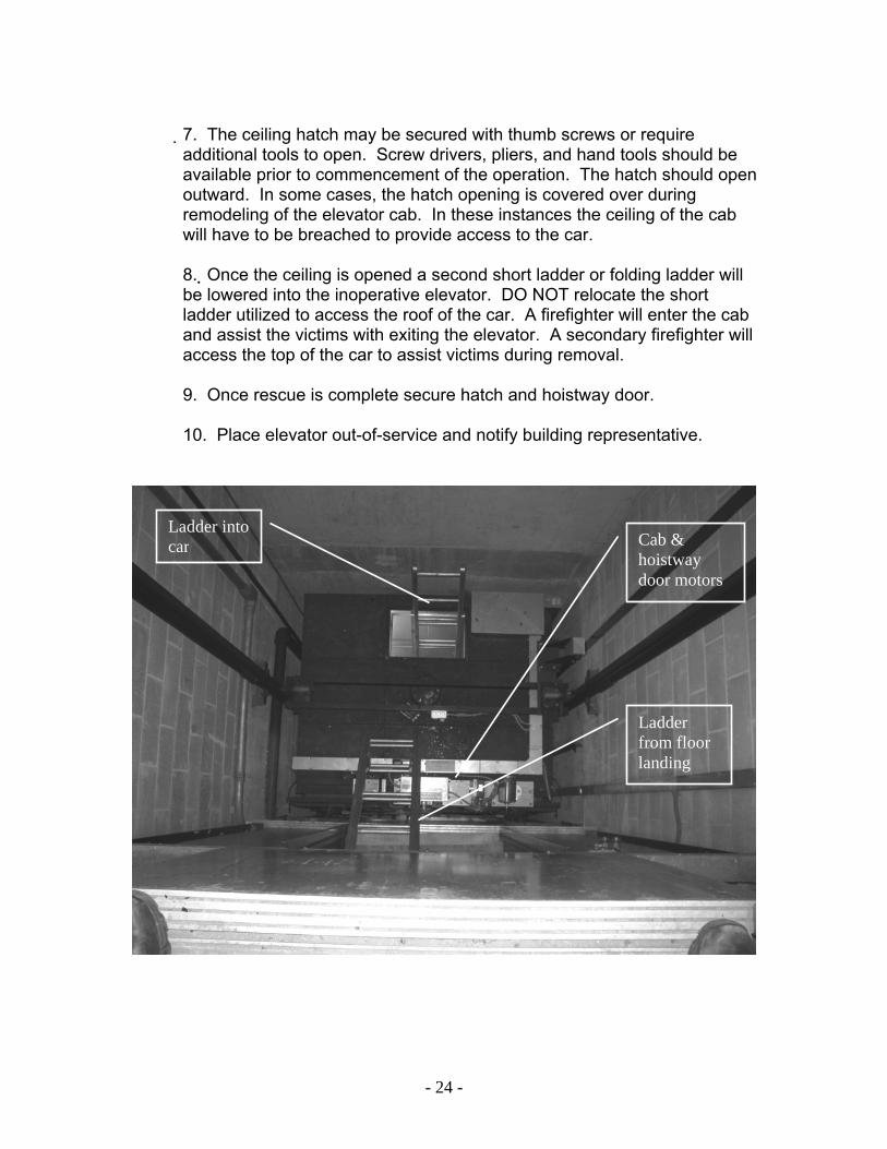
7. The ceiling hatch may be secured with thumb screws or require additional tools to open. Screw drivers, pliers, and hand tools should be available prior to commencement of the operation. The hatch should open outward. In some cases, the hatch opening is covered over during remodeling of the elevator cab. In these instances the ceiling of the cab will have to be breached to provide access to the car. 8. Once the ceiling is opened a second short ladder or folding ladder will be lowered into the inoperative elevator. DO NOT relocate the short ladder utilized to access the roof of the car. A firefighter will enter the cab and assist the victims with exiting the elevator. A secondary firefighter will access the top of the car to assist victims during removal. 9. Once rescue is complete secure hatch and hoistway door.
10. Place elevator out-of-service and notify building representative.
Ladder into car Cab &
hoistway door motors
Ladder from floor landing
- 25 -
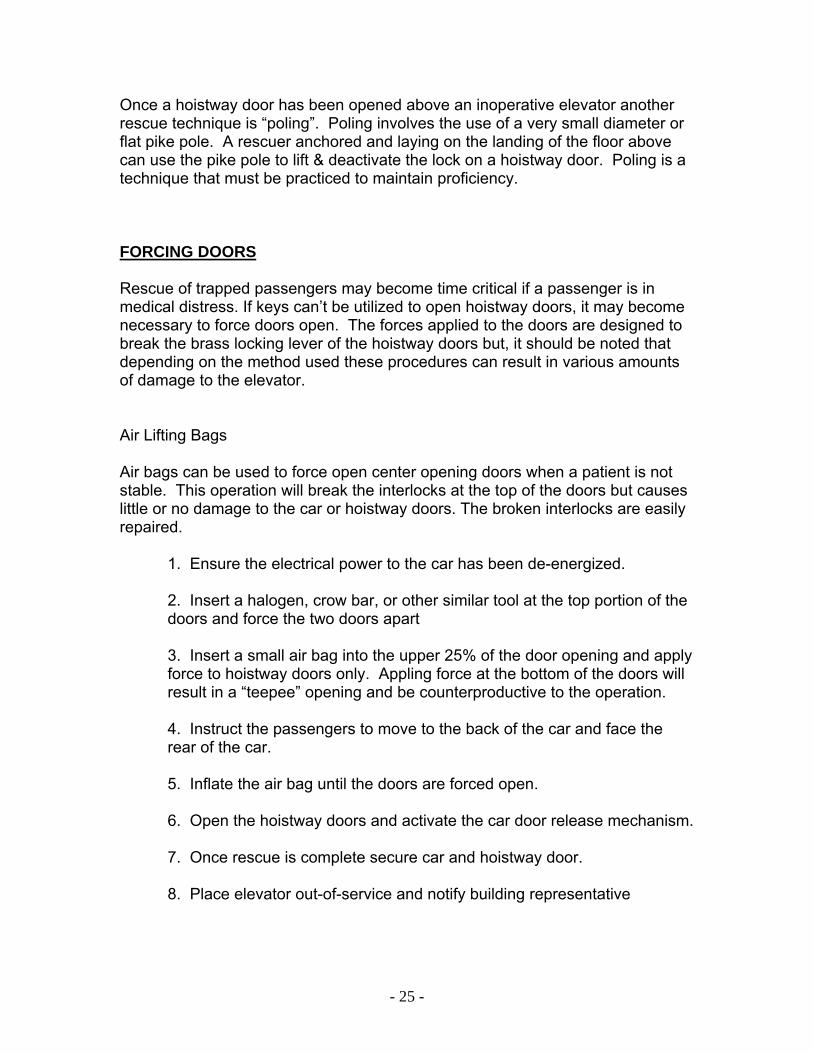
Once a hoistway door has been opened above an inoperative elevator another rescue technique is “poling”. Poling involves the use of a very small diameter or flat pike pole. A rescuer anchored and laying on the landing of the floor above can use the pike pole to lift & deactivate the lock on a hoistway door. Poling is a technique that must be practiced to maintain proficiency. FORCING DOORS Rescue of trapped passengers may become time critical if a passenger is in medical distress. If keys can’t be utilized to open hoistway doors, it may become necessary to force doors open. The forces applied to the doors are designed to break the brass locking lever of the hoistway doors but, it should be noted that depending on the method used these procedures can result in various amounts of damage to the elevator. Air Lifting Bags Air bags can be used to force open center opening doors when a patient is not stable. This operation will break the interlocks at the top of the doors but causes little or no damage to the car or hoistway doors. The broken interlocks are easily repaired.
1. Ensure the electrical power to the car has been de-energized. 2. Insert a halogen, crow bar, or other similar tool at the top portion of the doors and force the two doors apart 3. Insert a small air bag into the upper 25% of the door opening and apply force to hoistway doors only. Appling force at the bottom of the doors will result in a “teepee” opening and be counterproductive to the operation. 4. Instruct the passengers to move to the back of the car and face the rear of the car. 5. Inflate the air bag until the doors are forced open. 6. Open the hoistway doors and activate the car door release mechanism. 7. Once rescue is complete secure car and hoistway door. 8. Place elevator out-of-service and notify building representative
- 26 -
Hydraulic Spreaders Hydraulic Spreaders can be used to force open hoistway doors when a patient is not stable. This operation will cause considerable damage to the hoistway doors and/or elevator cab. All options should be considered prior to this type of operation.
1. Ensure the electrical power to the car has been de-energized. 2. Instruct the passengers to move to the back of the car and face the rear of the car. 3. Insert the hydraulic spreaders between the hoistway doors and force the two doors apart. If possible place a small piece of cribbing between spreader tips and door to distribute force. Place the spreader tips on the upper 2/3 of the hoistway doors.
Airbag Insertion Point
- 27 -
4. Open the hoistway doors and activate the car door release mechanism. 5. Once rescue is complete secure car and hoistway door. 6. Place elevator out-of-service and notify building representative
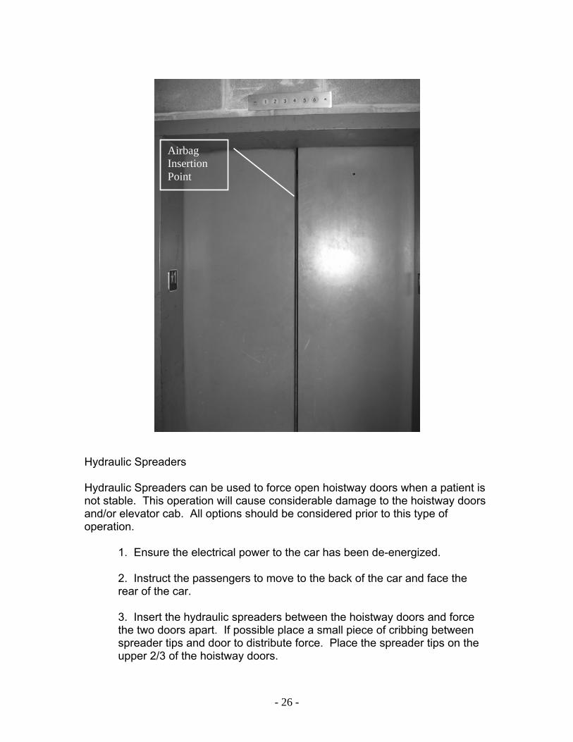
MOVING AN ELEVATOR As a moving elevator approaches a landing, the pick-up arm on the elevator car will engage rollers on the hoistway doors and disengage the hoistway door locks. A stalled elevator car in a blind shaft can be manually lowered to a landing in order to disengage the locks and remove victims. On most elevators the hoistway doors will disengage if the car is either eighteen inches above or below the floor level. The major difference in rescuing trapped passengers from a hydraulic or cable elevator is the method used to lower the elevator to floor level. Moving a hydraulic elevator will not be attempted until the elevator mechanic is on-location and coordinating the operation. The following is an overview of this type of operation with a hydraulic elevator. HYDRAULIC ELEVATORS
1. Ensure the electrical power to the car has been disconnected.
Locking Lever
Locking Lever

- 28 -
2. Instruct the passengers to move to the back of the car.
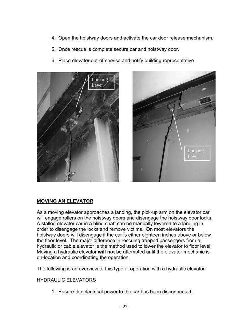
3. The elevator mechanic in the elevator equipment room will locate the bleeder lowering valve. The bleeder valves are located on the hydraulic power unit in the equipment room. There are generally three valves on this unit, one to raise the car, one to lower the car, and one that will level the car to a floor landing. Most bleeder valves have a manual lowering screw built into the valve and are marked ML, MAN, or MANUAL near the lowering screw. No valve should be fully opened. Open the bleeder valve SLOWLY, just enough to hear the sound of fluid flowing, and the elevator car will slowly lower. Firefighters outside the elevator car must relay information and status reports to the firefighters in the control room with the mechanic. 4. When firefighters outside the elevator observe the car is level or within six inches of the floor landing, advise the mechanic in the control room to discontinue bleeding the hydraulic fluid. The valve will be rotated in the opposite direction until the valve is seated. This will stop the car.
Manual Lowering Valve
- 29 -
5. Firefighters on the landing will manually open the hoistway and car doors. Quite often the mechanism on the car door that engages the hoistway door to facilitate its opening fails. This leaves the car door open and the hoistway door closed. It should be realized that when this occurs the easiest fix is to direct the passengers to move the latching mechanism (metal rod) upward. The latching mechanism connects the hoistway door rollers to the hoistway door latch. 6. Once rescue is complete secure cab and hoistway door. 7. Place elevator out-of-service and notify building representative.
CABLE ELEVATORS Cable elevators will not be lowered manually for rescue of occupants. Officers are advised to attempt other means of rescue and consult with the elevator mechanic. If the rescue operation is in question, request US&R to respond to the incident. ADJACENT CAR RESCUES When an inoperative elevator shares a common shaft with an operational elevator, it is possible to affect a rescue from an adjacent elevator. Due to the operation being conducted in an open elevator shaft, USAR should be requested prior to implementing the rescue operation. ROPE RESCUE Technical rope rescue can be utilized to rescue victims in an inoperative elevator in a blind shaft. Ambulatory and non-ambulatory victims can be rescued by utilizing a Stokes Basket. Trained firefighters can be lowered to the stalled elevator, secure the victims, and have them hauled to a safe landing. USAR teams should be requested to perform this type of rescue. BREACHING ELEVATOR SHAFTS Occasionally, an express elevator car may be stalled in a blind section of an elevator shaft, and as a final resort it will be necessary to breach an elevator shaft wall. Elevators of more sophisticated design have access panels from blind floors. These panels may be every three floors or 80-feet apart. Panels can be
- 30 -
helpful but should not be depended upon, as they may be hidden or covered. Shaft panels are on the side of the elevator shaft that the car door is located on. These panels can be removed and used in several ways:
• Locate car by looking into shaft through a panel. If close enough, the car doors can be forced open and passengers removed through the panel. • Panels can permit entry into the elevator shaft and access to the emergency exit on the roof of a car. • If there are no shaft panels and it is necessary to breach the elevator shaft wall, USAR will be requested prior to this type of rescue being utilized. The breach opening(s) should be made on the elevator car door side of the shaft and as near the car door as possible. The wall opening should be large enough to expose the entire elevator car door opening.
Remember, breaching requires personnel, labor, time, property damage, planning and coordination. Other forms of rescue should be evaluated prior to commencing breaching operations.
- 31 -
OTHER ELEVATOR EMERGENCIES CAUGHT OR PINNED BY ELEVATOR CAR Victim extrication requires the combined resources of firefighters and the elevator mechanic. The firefighters bring field experience, ingenuity, and tools. The elevator mechanic brings technical expertise and knowledge not only of the entire system but also knowledge of the specific elevator equipment involved in the incident. The medical condition of the victim caught by the car or counterweight must be determined. This will become a factor in what type of extrication is preformed and the EMS needs on-scene. Hand tools and levers can provide some relief for a hand or foot, but a whole body or limb requires more in-depth operations. USAR teams will be requested to assist in complex extrication operations. The USAR team can provide additional personnel and specialized tools for the extrication. During extrication operations rescuers and the victim should be tethered to an anchor. The following is a guideline for these type of extrications. • Secure the elevator by fastening it on both sides with slings from come-along type units and lifting straps rated for this heavyweight work. They can be fastened onto the rail guide brackets above the car and attached to the crosshead beam area. • To gain a small amount of movement; insert long steel pry bars into the space on either side of the entrapment. It is a fact that elevators crush very effectively, and the entrapped part may be freed readily. • If that didn’t provide the needed movement, then the elevator mechanic may be able to remove the guide wheels on the affected side to provide a limited amount of movement. This would allow the car to be moved slightly back into the shaft, to provide relief. • Further movement can be obtained on a cable elevator by having the elevator mechanic cut the guide rail opposite the affected side, above and below the elevator. This will allow the car to be pushed backward in the shaft. Do not loosen or remove the guides of a hydraulic elevator. The added movement of the car places dangerous stresses on the cylinder system.
- 32 -
ELEVATOR FIRES Fires occur in elevator cars as a contents fire, these cause smoke problems on multiple floors. Fires also occur in the elevator equipment room, elevator pit, and in the cab door motors. Due to the many complex issues with fighting elevator fires and this document addressing the rescue aspect of elevator emergencies, only general causes of fire and the effects on the car will be addressed. ELEVATOR CAR Elevator car fires are rare. The cause of the fire is usually not the car itself but trash or prohibited items stored in an abandoned car. An intense fire can warp the hoistway door and expose the hallway. Damage to the guide rails and cables could place the car in danger of falling. The incident commander and safety officer should be made aware of the elevator car involvement. Precautions should be taken to protect firefighters from a possible falling car. EQUIPMENT ROOM When a fire occurs in an elevator equipment room, the probable seat of the fire will be the driving motor or overheated hydraulic fluid. Disconnecting the main and auxiliary power switches will stop car movement and de-energize the driving motor. Whenever possible, the use of water on elevator equipment should be avoided and dry powder extinguishers used. The removal of passengers from the shut down elevator car should be completed in a routine manner and the room ventilated. ELEVATOR PIT Although there is little to burn in an elevator shaft, there is the presence of grease and lint. However, the main source of fuel is debris in the pit. The principal hazard of any fire in an elevator shaft is the smoke created by the fire. Smoke can cause problems by extending to an elevator car with passengers or to other levels in the multi-story building.
If the fire is under the car, the car should be brought to the lowest landing possible to reduce the spread of smoke. If the fire is in the upper portion of the shaft, the car should be stopped and evacuated and the elevator shaft opened as near to the fire as possible. Remember, the use of water should be avoided or used sparingly and power should be shut down as soon as practical. When multiple elevators share a common shaft, all elevators in the elevator shaft involved with fire should be stopped and evacuated.

- 33 -
CAB DOOR MOTOR Signs of this type of situation are the characteristic “electrical” odor in the car. passengers should be removed from all the elevators in the bank. The elevators should be powered down and secured. The ceiling of the cab can be inspected from the ceiling hatch or by opening the hoistway doors on the floor above. POWER OUTAGE During the 1965 East Coast power outage, thousands of elevators were stalled. The greatest problem was panic to trapped passengers in dark inoperative elevator cars. When there is a sudden loss of power, all power switches should be placed in the off position and passengers rescued with appropriate measures. It may be necessary to force doors, or breach walls. Some buildings have auxiliary power which can be used to move elevators until normal power is restored.

- 34 -
ESCALATORS
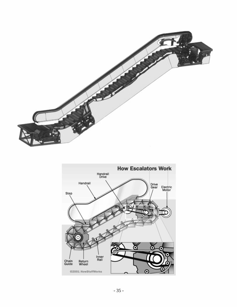
Escalators are a simple and common means of transportation. They consist of steps, a driving motor, and gearing to form a continuous belt or track running on a set of gears. An escalator traveling between 90 to 120 feet per minute can carry as many as 5000 passengers per hour. Each escalator in a building is an individual installation with separate machinery and controls. A stop button that may be located externally and adjacent to the top and bottom of each unit. Stop buttons stop the escalator slowly and are provided for emergency operation. An escalator cannot be restarted without the use of a key-operated switch located in a covered compartment at the bottom of the escalator. There are occasional emergencies such as children inserting their fingers and toes between the stop treads and guard plates, shoes that are capable of wedging between the treads, and trapped fingers due to persons attempting to pick up dropped articles. Generally, most injuries are not serious. A moving escalator can be stopped by activating the stop button. By clearing the escalator of all passengers, the treads can be moved backwards by hand pressure. Some older installations may require the use of a halligan or pry bar to push the treads backwards. When pushed backwards, trapped fingers or toes can be easily removed and the victim removed from the escalator. Because of a victim’s position and/or the extent of injuries, it may be necessary to remove the cover plate that covers the step treads at the landing. When landing plate removal is necessary, the plate screws should be completely removed from the plate and the plate lifted straight up rather than backwards or away from the victim. Following removal of the victim, place the escalator out of service. With power removed the escalator becomes an ordinary staircase. If a victim can’t be freed following these procedures, request USAR response to the incident. USAR apparatus are equipped with specialty tools and equipment for this type operation. Request needed medical resources.
- 35 -
- 36 -
GLOSSARY
Alarm Bell: Used to notify occupants of a building there is an elevator problem. A bell is activated by use of an emergency switch on most elevators. Blind Shaft: The part of an elevator shaft that for 3 or more consecutive floors has no hoistway doors to access the floors. Buffers: Buffers smoothly decelerate an elevator car and support it at rest as it passes the lowest floor landing. Car: The moveable part of an elevator used to move passengers. Construction is identical for cable or hydraulic cars except cable cars will have a reinforced top beam due to cable connections. This beam has to be able to carry the load of the car and passengers. Hydraulic elevators have a reinforced bottom joist due to the hydraulic ram connected to the bottom of the car. This beam has to be able to carry the load of the car and passengers. Car Door: The door on the elevator car. Counterbalance Weights: All cable elevators are counterbalanced. Hydraulic elevators over six stories in height also need to be counterbalanced. Counterbalance weights are normally on the back of the elevator shaft. However, due to construction of a building, oversize cars, and other similar factors, the weights may be on the side of the elevator shaft. Door Roller or Release Roller: Generally on the hoistway doors. Activation of this roller will open the door latch, lock, or interlock. Elevator Shaft: A shaft that contains an elevator car and appropriate equipment. Emergency Exit: Most elevators are equipped with a ceiling emergency exit. When there is a bank of elevators, a side emergency exit may be in the side of the car.
- 37 -
Emergency Stop Switch: A manually operated switch that will shut off the electric power to an elevator. The switch is red and may be labeled stop and run, or emergency. Emergency Switch (PUSH IN CASE OF FIRE): Override switch on photo electric light beam for closing the car doors. This switch can be used to close the doors when smoke from a fire keeps the doors from closing. Equipment Room: The equipment room for cable elevators is normally located on the top floor or roof of a building. In rare occasions, it is in the basement. Equipment rooms for hydraulic elevators are normally located at the lower level of a building, but can be at any floor level or 50 to 100 feet away from the elevator shaft. Express Elevators: An elevator car that has no hoistway doors to access three or more consecutive floors. Gib Block: Guides on the bottom of hoistway doors that provide stability for opening and closing. Governor: A mechanical device on cable elevators. If a car is traveling downward too fast, it automatically activates a mechanism on the car and causes the safeties to grip the guide rails and stop the car. If a car is traveling upward too fast, it will cause the electric motor to be shut off and slow the movement of the car and set the brakes on the motor, stopping the car. Hoistway Door: The door that is seen from each floor of a building. Hoistway Door Lock (Interlock): Generally located on the beam over the elevator shaft opening, but may also be on the side of an elevator shaft opening. This device locks the hoistway doors in a closed position. Lowering Valve: Valve on hydraulic elevator equipment used to lower a car. If there is no manual lowering screw in the valve, there will be a globe valve in the system that can be used to lower an elevator car. This is the valve that is used by an elevator mechanic to lower a car.
- 38 -
Main Switch: Main power switch located in the machine room. Pick-Up Arm Clutch, Vane, Cam, or Bayonet: Located on the hoistway door of an elevator and actuates the door roller that operates the door latch. It is generally, 14 inches long on hydraulic elevators, and 36 inches long on cable elevators. Pit Area: Area at the bottom of the elevator shaft. Power Door Operator: Located on top of an elevator car or at each floor landing. Comprised of an electric motor that opens and closes the doors. Power Unit: Electric motor to operate hydraulic pump or move cables, located in a equipment room. Push Button Station: Located at each floor landing and close to the hoistway door opening. Relays: Activates the movement of an elevator car and its doors. Located in relay panels or control panels in an equipment room. Safeties: Mechanical device on the bottom of cable elevator cars that is activated by the governor if the downward car speed is too fast. Safeties grip the guide rails and stop the car. Sleeping Elevator, or Parked Car: When an elevator car is not in use. Traction Sheave: Large pulley to provide movement of cables driven by the motor.