elevator controller for i ms biomedical …bme200/elevator_control_f06/reports/final_design... ·...
TRANSCRIPT

ELEVATOR CONTROLLER FOR INDIVIDUAL WITH MS Biomedical Engineering Design 201/301
University of Wisconsin - Madison
Sara Karle – Co-Team Leader Ashley Matsick – Co-Team Leader
Michele Lorenz – Communications
Alison Boumeester – BSAC
Peter Strohm – BWIG
Client: John Fleming, MD Department of Neurology, UW Medical School
Advisor: John Webster, PhD
Professor Emeritus, Department of Biomedical Engineering
DECEMBER 12, 2006

2
TABLE OF CONTENTS
Abstract 3
Statement of design problem 3
Background and motivation 3-4
Design constraints
Adaptive controls 4-5
Mounting arm 5-7
Weatherproof housing 8
Evaluation of alternative solutions
Adaptive controls 8-9
Mounting arm 9-13
Final design
Adaptive controls 13-16
Mounting arm 16-17
Weatherproof housing 17-18
Conclusions: Ethical considerations and future development 18-19
References 20
Appendix A: Product design specifications 21-22
Appendix B: Project costs (Fall 2006) 23
3
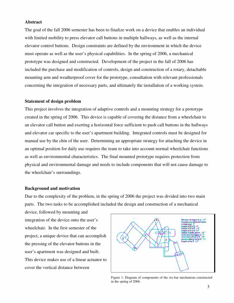
Figure 1. Diagram of components of the six-bar mechanism constructed in the spring of 2006.
Abstract
The goal of the fall 2006 semester has been to finalize work on a device that enables an individual
with limited mobility to press elevator call buttons in multiple hallways, as well as the internal
elevator control buttons. Design constraints are defined by the environment in which the device
must operate as well as the user’s physical capabilities. In the spring of 2006, a mechanical
prototype was designed and constructed. Development of the project in the fall of 2006 has
included the purchase and modification of controls, design and construction of a rotary, detachable
mounting arm and weatherproof cover for the prototype, consultation with relevant professionals
concerning the integration of necessary parts, and ultimately the installation of a working system.
Statement of design problem
This project involves the integration of adaptive controls and a mounting strategy for a prototype
created in the spring of 2006. This device is capable of covering the distance from a wheelchair to
an elevator call button and exerting a horizontal force sufficient to push call buttons in the hallways
and elevator car specific to the user’s apartment building. Integrated controls must be designed for
manual use by the chin of the user. Determining an appropriate strategy for attaching the device in
an optimal position for daily use requires the team to take into account normal wheelchair functions
as well as environmental characteristics. The final mounted prototype requires protection from
physical and environmental damage and needs to include components that will not cause damage to
the wheelchair’s surroundings.
Background and motivation
Due to the complexity of the problem, in the spring of 2006 the project was divided into two main
parts. The two tasks to be accomplished included the design and construction of a mechanical
device, followed by mounting and
integration of the device onto the user’s
wheelchair. In the first semester of the
project, a unique device that can accomplish
the pressing of the elevator buttons in the
user’s apartment was designed and built.
This device makes use of a linear actuator to
cover the vertical distance between
4
Background and motivation continued
buttons and a six bar mechanism to cover the horizontal distance to the buttons (Figure 1). The
device is powered by a 12 volt battery, and requires two separate switches for operation. The
device has been tested on the buttons in the user’s elevator and sufficient force is produced to
engage the buttons. The portion of the project that remained to be accomplished this semester
included docking of the device on the user’s chair, incorporation of adaptive controls to allow the
user to operate the device, and a weatherproof covering to protect the entire device.
Our client, Dr. Fleming, currently treats a patient with multiple sclerosis (MS). This patient was
fully mobile earlier in life, but has since been diagnosed with MS. The early stages of the disease
consisted of attacks followed by partial recovery, but now MS has progressed and left him
paralyzed from the neck down. He lives independently in a second-floor apartment by making use
of infrared technology produced by SiCare; this system allows him to operate many household
appliances with his voice alone. The user can control his lights, fan, TV, DVD player, and change
the channels and volume on the latter devices by speaking the appropriate command. Similarly, he
can nudge a switch mounted on his wheelchair to open the main apartment door.
When the user leaves his apartment, he travels around using the Madison Metro bus service, and is
thus very mobile. The rate-limiting step, however, is his inability to press the elevator buttons in his
apartment complex to move between his apartment and the building exit. He is dependent on others
to press the elevator call button in the hallway as well as the appropriate floor button in the elevator.
When no one is available in the apartment to assist him, he is unable to travel between his home and
any exterior environments. Our device aims to provide the user with a means by which he can press
the elevator buttons to get around independently (Karle et al. 2006).
Design constraints
Adaptive controls
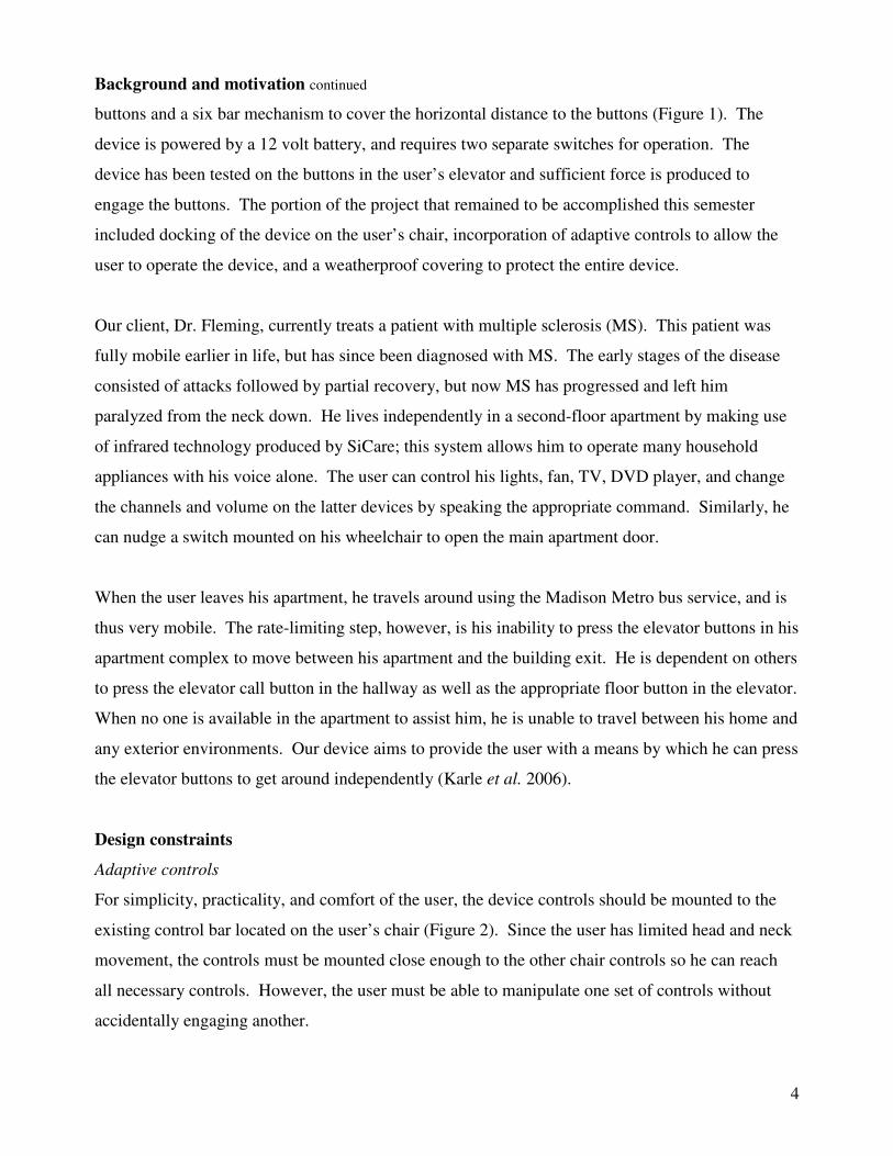
For simplicity, practicality, and comfort of the user, the device controls should be mounted to the
existing control bar located on the user’s chair (Figure 2). Since the user has limited head and neck
movement, the controls must be mounted close enough to the other chair controls so he can reach
all necessary controls. However, the user must be able to manipulate one set of controls without
accidentally engaging another.
5
Figure 2. Photograph of the user’s control bar that currently has his chin joystick (left) and tilt control (right) installed within the optimal range for use.
Design constraints: Adaptive controls continued
A minimum amount of space must exist between
existing chair controls and any new elevator controls
to ensure this. The controls must be mounted far
enough to the left on the control bar so that the user
can see the device while contacting a control,
enabling him to visually align to device with the
desired elevator button. For safety reasons, the
controls must be made weatherproof so that they
continue to function in variable weather conditions without endangering the user or compromising
the function of the controls. Finally, the size and weight of the controls and control housing must
be minimized in order to conserve the user’s field of vision and reduce physical stress applied to the
control bar.
In order to control the device’s bidirectional linear actuator and pull solenoid, two types of switches
are required. The bidirectional linear actuator runs on 12 V DC and draws a current of at most one
amp. Since the motor is bidirectional, the switch must be able to reverse the current direction in
addition to having an off position. This switch must have a way to hold an on position so that the
user can run the linear actuator up or down as far as needed without repeatedly engaging the switch.
The solenoid also runs on 12 V DC, but it draws a higher current of 5 amps. The solenoid switch
need only be a momentary contact switch since the solenoid is required to extend outward for just a
short period of time. To minimize the addition of parts to the power chair, the device and controls
must be powered by the existing 12 V DC batteries on the user’s chair. Therefore both of these
switches and any other circuit elements must be able to handle 12 V DC running through them, as
well as the corresponding current levels.
Mounting arm
In order for the constructed prototype to function in the user’s specific environment, it must be
connected to the wheelchair and situated in the proper position. Many different constraints impose
requirements on the design and construction of the mounting arm, most significantly those dictated
by the wheelchair geometry and functions.

6
Figure 4. Illustration of normal chair width (between armrests) and maximum chair width allowing wheelchair to pass through doorways.
Figure 3. Photo of the user’s wheelchair; the stationary base is signified by the black bracket and the tilting seat by the white bracket. The only location that would support a wrap-around bracket is denoted by the white arrow. The point of rotation for the chair’s footrests is illustrated by the light blue arrow.
Design constraints: Mounting arm continued
Before further issues could be addressed, the mounting location had to be determined by evaluating
the accessibility, size, and orientation in space of possible sites. The seat angle of the chair is highly
variable due to an existing control that allows the user to change the setting based on comfort. The
majority of the wheelchair’s structure is contained in the seat; in order to mount the device on a
permanently stationary component, the mounting site must be on the base of the chair (Figure 3).
Another important requirement was discovered
when the group discussed normal chair operation
with the user; an important daily function is the
rotation of the chair’s footrests away from each
other (Figure 3). If any component of the
mounting arm assembly extends forward into the
rotary path of the footrests, it needs to be capable
of either translation or rotation to avoid causing
restriction of footrest motion. The position of
the device during use requires stability, however,
so a locking mechanism is required in order to
keep the arm from translating or rotating at the
wrong time.
Based on where the mounting arm would be optimally attached to
the wheelchair (on the stationary bar of the chair base), a
horizontal component is necessary to move the mounted device
out away from the wheelchair. In order to clear the armrests and
footrests, the center of the device must be at least 5.5 inches away
from the outside surface of the stationary bar. The total distance
added to the chair past the armrests, however, may not exceed 7
inches; movement of the chair through the narrowest doorway in
the user’s apartment building would be hindered if any part
extended too far out from the side of the chair (Figure 4).

7
Figure 6. Illustration of stationary bar (A) on wheelchair base, rubber button presser (B) on prototype, alarm button (C) and third floor button (D) with relational heights indicated to demonstrate the proposed location of the prototype with respect to the stationary bar. The bottom surface of the prototype must be approximately 13.25 inches above the ground. Thus, any component supporting the weight of the device must be 0.45 inches below the top surface of (A).
Figure 5. Top view of user’s typical wheelchair position inside the elevator. The distance (F) from the left-hand wall to the center of the buttons is 18.5 inches; from the same wall to the mounting position on the stationary bar is a distance (G) of 22.2 inches.
Design constraints continued
When the user pulls into the elevator, he turns his chair and moves forward until his toes are
touching the left-hand wall (Figure 5). Mounting the device directly perpendicular to the proposed
site on the stationary bar will not position the device far
enough forward to allow the user access the elevator car
buttons. The distance from the left-hand wall to the center of
the buttons is 18.5 inches, while the distance from the end of
the chair footrests to the proposed mounting site is 22.2 inches
(Figure 5). Moving the device to a position more optimally
aligned with the buttons requires one of the mounting arm
components to extend forward at least 7.2 inches in the
direction of the chair’s footrests. An extension of this size
provides sufficient distance to line the center of the device up
with the center of the buttons and includes several inches of
extra material to support the entire base are of the device.
Within the elevator car and in the hallways of the user’s apartment building, the lowest necessary
button activates an alarm system in the elevator cab in case of emergency. This button is located 35
inches above the floor, and is exactly 12 inches from the
highest button in the building (the third floor button
within the elevator cab). The device is approximately
21.75 inches from the base surface to the rubber button
presser, leaving 13.25 inches between the base and the
floor. Due to the height of the stationary bar, it was
determined that the base of the device must be 0.45
inches lower than the bar’s top surface (Figure 6).
Finally, due to the experimental nature of this
project and the expectation that components will need to
be maintained or replaced, all components of the
mounting arm need to be removable from one another,
the chair, and the device.
8
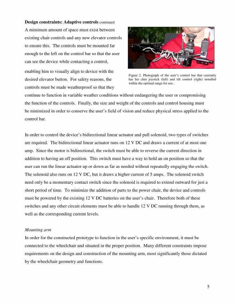
Figure 7. Components included in the purchase of the Sip and Puff switch distributed by Enabling Devices.
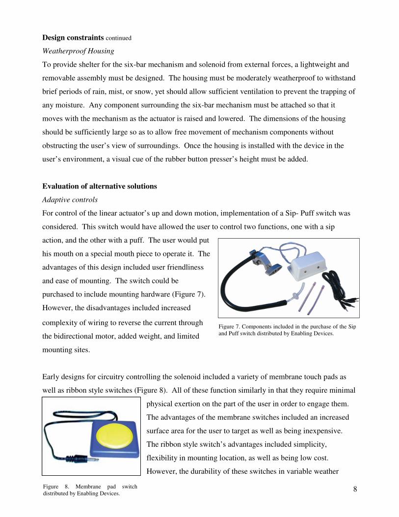
Figure 8. Membrane pad switch distributed by Enabling Devices.
Design constraints continued
Weatherproof Housing
To provide shelter for the six-bar mechanism and solenoid from external forces, a lightweight and
removable assembly must be designed. The housing must be moderately weatherproof to withstand
brief periods of rain, mist, or snow, yet should allow sufficient ventilation to prevent the trapping of
any moisture. Any component surrounding the six-bar mechanism must be attached so that it
moves with the mechanism as the actuator is raised and lowered. The dimensions of the housing
should be sufficiently large so as to allow free movement of mechanism components without
obstructing the user’s view of surroundings. Once the housing is installed with the device in the
user’s environment, a visual cue of the rubber button presser’s height must be added.
Evaluation of alternative solutions
Adaptive controls
For control of the linear actuator’s up and down motion, implementation of a Sip- Puff switch was
considered. This switch would have allowed the user to control two functions, one with a sip
action, and the other with a puff. The user would put
his mouth on a special mouth piece to operate it. The
advantages of this design included user friendliness
and ease of mounting. The switch could be
purchased to include mounting hardware (Figure 7).
However, the disadvantages included increased
complexity of wiring to reverse the current through
the bidirectional motor, added weight, and limited
mounting sites.
Early designs for circuitry controlling the solenoid included a variety of membrane touch pads as
well as ribbon style switches (Figure 8). All of these function similarly in that they require minimal
physical exertion on the part of the user in order to engage them.
The advantages of the membrane switches included an increased
surface area for the user to target as well as being inexpensive.
The ribbon style switch’s advantages included simplicity,
flexibility in mounting location, as well as being low cost.
However, the durability of these switches in variable weather
9
Evaluation of alternative solutions continued
conditions was questionable, as well as whether or not the user could reasonably use these to
operate the device.
For weatherproofing the circuit components, purchasing switches that come already weatherproofed
was considered, as well as purchasing special switch coverings which could be used in conjunction
with a mounting surface to attach the controls to the user’s control bar. The advantage of a pre-
weatherproofed switch is that the manufacturer has already ensured it will function in a variety of
climate conditions. However, this greatly limited the selection of switches to choose from, which
compromised user friendliness and mounting options. The advantage of special switch cover plates
was that multiple switches could be encased and mounted together in one mounting surface. The
disadvantage was that only certain switches fit into these special covers, so the controls became less
user friendly and it was required that additional weight be added to the control bar.
Mounting Arm
In order to address the requirements of the mounting arm, three designs were drafted. The
requirements for this arm included several aspects: an extension perpendicular to the wheelchair, an
extension parallel to the wheelchair, a bracket to attach the arm to the wheelchair, and a way to
move the device into a position that eliminated interference with the movement of the wheelchair
leg rests. Also, the entire system had to be removable from the wheelchair, and no design could
damage or alter any existing part of the wheelchair. Based on feasibility of construction, how well
each design addressed the requirements, and required materials, a final design was chosen based on
an amalgam of the three proposed designs.
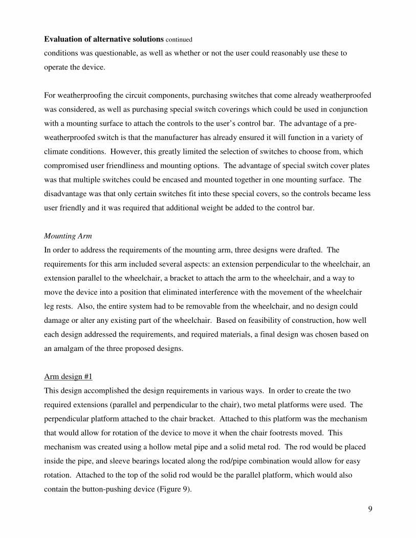
Arm design #1
This design accomplished the design requirements in various ways. In order to create the two
required extensions (parallel and perpendicular to the chair), two metal platforms were used. The
perpendicular platform attached to the chair bracket. Attached to this platform was the mechanism
that would allow for rotation of the device to move it when the chair footrests moved. This
mechanism was created using a hollow metal pipe and a solid metal rod. The rod would be placed
inside the pipe, and sleeve bearings located along the rod/pipe combination would allow for easy
rotation. Attached to the top of the solid rod would be the parallel platform, which would also
contain the button-pushing device (Figure 9).
10
Figure 9. Components of the first mounting arm design.
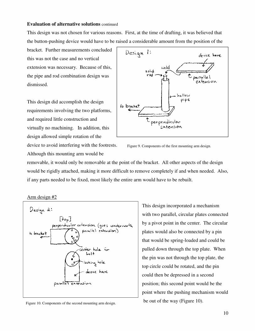
Figure 10. Components of the second mounting arm design.
Evaluation of alternative solutions continued
This design was not chosen for various reasons. First, at the time of drafting, it was believed that
the button-pushing device would have to be raised a considerable amount from the position of the
bracket. Further measurements concluded
this was not the case and no vertical
extension was necessary. Because of this,
the pipe and rod combination design was
dismissed.
This design did accomplish the design
requirements involving the two platforms,
and required little construction and
virtually no machining. In addition, this
design allowed simple rotation of the
device to avoid interfering with the footrests.
Although this mounting arm would be
removable, it would only be removable at the point of the bracket. All other aspects of the design
would be rigidly attached, making it more difficult to remove completely if and when needed. Also,
if any parts needed to be fixed, most likely the entire arm would have to be rebuilt.
Arm design #2
This design incorporated a mechanism
with two parallel, circular plates connected
by a pivot point in the center. The circular
plates would also be connected by a pin
that would be spring-loaded and could be
pulled down through the top plate. When
the pin was not through the top plate, the
top circle could be rotated, and the pin
could then be depressed in a second
position; this second point would be the
point where the pushing mechanism would
be out of the way (Figure 10).
11
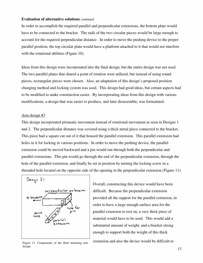
Figure 11. Components of the third mounting arm design.
Evaluation of alternative solutions continued
In order to accomplish the required parallel and perpendicular extensions, the bottom plate would
have to be connected to the bracket. The radii of the two circular pieces would be large enough to
account for the required perpendicular distance. In order to move the pushing device to the proper
parallel position, the top circular plate would have a platform attached to it that would not interfere
with the rotational abilities (Figure 10).
Ideas from this design were incorporated into the final design, but the entire design was not used.
The two parallel plates that shared a point of rotation were utilized, but instead of using round
pieces, rectangular pieces were chosen. Also, an adaptation of this design’s proposed position
changing method and locking system was used. This design had good ideas, but certain aspects had
to be modified to make construction easier. By incorporating ideas from this design with various
modifications, a design that was easier to produce, and later disassemble, was formulated.
Arm design #3
This design incorporated prismatic movement instead of rotational movement as seen in Designs 1
and 2. The perpendicular distance was covered using a thick metal piece connected to the bracket.
This piece had a square cut out of it that housed the parallel extension. This parallel extension had
holes in it for locking in various positions. In order to move the pushing device, the parallel
extension could be moved backward and a pin would run through both the perpendicular and
parallel extensions. This pin would go through the end of the perpendicular extension, through the
hole of the parallel extension, and finally be set in position by turning the locking screw in a
threaded hole located on the opposite side of the opening in the perpendicular extension (Figure 11).
Overall, constructing this device would have been
difficult. Because the perpendicular extension
provided all the support for the parallel extension, in
order to have a large enough surface area for the
parallel extension to rest on, a very thick piece of
material would have to be used. This would add a
substantial amount of weight, and a bracket strong
enough to support both the weight of this thick
extension and also the device would be difficult to

12
Figure 12. Components of the first bracket design.
Evaluation of alternative solutions continued
make given the small space available for a bracket to be placed. Also, square holes are difficult to
make, so if this design were to be changed by using a rod and a circular hole, multiple problems
would arise concerning the mounting of the device on the parallel extension. Overall, the level of
machining and construction required for this design would not have been feasible to complete in the
given time.
The major advantage of this design is the fact that all pieces could be removed easily. Any repairs
could be made to individual pieces, whereas the previous two designs did not have this advantage.
When drafting the final design, this aspect was made a priority, and this design provided inspiration
for that.
Bracket design #1
The proposed bracket for this design utilized a U-shaped metal piece that contained a bolt through
the bottom two pieces of the “U” in order to provide a way to tighten around the stationary bar of
the chair (Figure 12). This would make the bracket
easily removable from the chair, and very simple to
manufacture. Because the bolt only had to go
through the bottom two pieces, thickness of material
wasn’t important: this bracket could be made
lightweight while still supporting the mounting arm
created. This design was chosen for the final design
because of its simplicity and the little material it
required. If this bracket ever had to be replaced,
substantial machining would not have to be
completed, making this bracket easily replaceable.
The disadvantage of this design is that it will not hold
well under great amounts of stress. However, the forces created by our device will be relatively
small and should not cause mechanical failure of the bracket.
Bracket design #2
This design used two pieces to clamp around the tubing on the wheelchair. Each piece consisted of
a C-shape with a flange on both the top and bottom. These flanges provided a point for a bolt to
13
Figure 13. Components of the second bracket design.
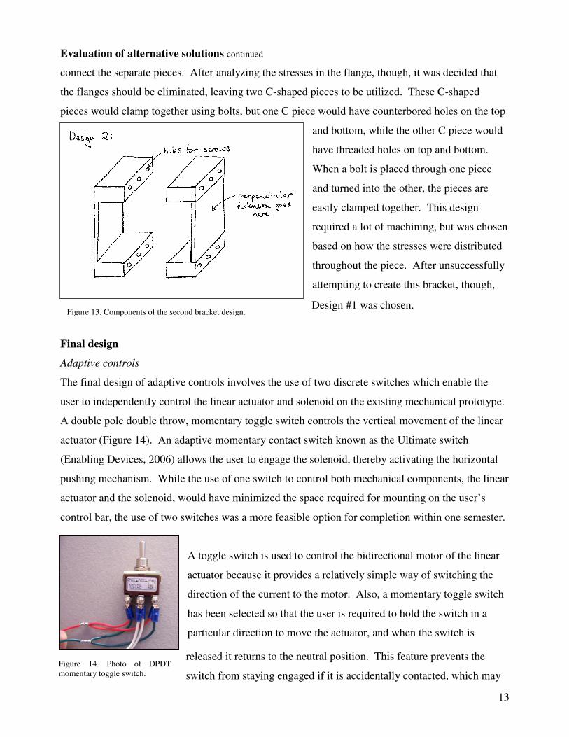
Figure 14. Photo of DPDT momentary toggle switch.
Evaluation of alternative solutions continued
connect the separate pieces. After analyzing the stresses in the flange, though, it was decided that
the flanges should be eliminated, leaving two C-shaped pieces to be utilized. These C-shaped
pieces would clamp together using bolts, but one C piece would have counterbored holes on the top
and bottom, while the other C piece would
have threaded holes on top and bottom.
When a bolt is placed through one piece
and turned into the other, the pieces are
easily clamped together. This design
required a lot of machining, but was chosen
based on how the stresses were distributed
throughout the piece. After unsuccessfully
attempting to create this bracket, though,
Design #1 was chosen.
Final design
Adaptive controls
The final design of adaptive controls involves the use of two discrete switches which enable the
user to independently control the linear actuator and solenoid on the existing mechanical prototype.
A double pole double throw, momentary toggle switch controls the vertical movement of the linear
actuator (Figure 14). An adaptive momentary contact switch known as the Ultimate switch
(Enabling Devices, 2006) allows the user to engage the solenoid, thereby activating the horizontal
pushing mechanism. While the use of one switch to control both mechanical components, the linear
actuator and the solenoid, would have minimized the space required for mounting on the user’s
control bar, the use of two switches was a more feasible option for completion within one semester.
A toggle switch is used to control the bidirectional motor of the linear
actuator because it provides a relatively simple way of switching the
direction of the current to the motor. Also, a momentary toggle switch
has been selected so that the user is required to hold the switch in a
particular direction to move the actuator, and when the switch is
released it returns to the neutral position. This feature prevents the
switch from staying engaged if it is accidentally contacted, which may

14
Figure 15. Diagram illustrating wire connections on momentary toggle switch.
Figure 16. Photo of toggle switch (right) before modifications were made.
Figure 17. Photo of modified toggle switch (left) and Ultimate switch (right).
Final design continued
lead to burnout of the motor. The toggle switch has a rating of 250 V AC at 15 amps and 125 V AC
at 25 amps. Each wire connecting to a terminal of the toggle switch is secured in a wire crimp,
which is subsequently screwed onto the terminal. The
arrangement of wire connections to the terminals allows for
reversal of the current direction (Figure 15). The wires
coming from the actuator that split to contact two different
switch terminals consist of one short wire soldered into a
longer wire.
The toggle switch, if mounted on the user’s chair as it is
manufactured, does not have a long enough lever arm to
allow the user to contact it (Figure 16). Therefore, a 5”
extension is added onto the existing lever arm to span the
distance from the control bar to within the user’s range of
motion (Figure 17). This is accomplished by securing a hollow aluminum rod (3/8” diameter) on
top of a rubber boot with epoxy. This rubber boot screws tightly onto the threaded portion of the
toggle switch, serving two purposes. First, it allows for attachment of the extension rod, and
second, it covers the toggle switch to create a weatherproof barrier. A rubber stopper is affixed to
the top of the extension rod, providing a large,
comfortable surface which the user can contact to
manipulate the switch. A hole is bored into the rubber
stopper to allow for tight insertion of the extension rod,
and the two components are secured together with
epoxy.
The Ultimate switch, which is used to control the
solenoid, is also a momentary contact switch, so it will
not stay engaged if it is accidentally contacted. The design of the Ultimate switch allows for
activation by pressing the lever arm in any direction, and requires minimal force to bend the lever.
The lever arm only needs to be tilted five degrees in any direction to engage. Therefore, the user is
able to activate the solenoid by contacting it in whatever direction is easiest. Also, this switch is

15
Figure 19. Diagram of switch housing base indicating holes for switch cords.
Figure 18. Photo of Ultimate switch installed in plastic housing case.
Final design continued
designed with a lever arm of approximately 5”, which places the switch at a comfortable distance
from the user’s chin when it is mounted beneath the control rod.
As purchased, the electrical connection to the Ultimate switch consists of a 1/8”mono plug. In
order to connect the switch to the battery and solenoid, a conversion must be made using a 1/8”
stereo phone jack. An in-line, solder-type stereo phone jack allows two wires to be soldered to two
discrete terminals. Therefore, when the plug on the Ultimate switch is plugged into the phone jack,
current is able to run into the Ultimate switch through one wire and out through the other.
Both the toggle switch and the Ultimate switch are mounted on the
user’s chair in a plastic housing box. This housing box consists of a
rectangular, open topped base and a matching rectangular lid which is
attached using screws in pre-drilled holes. The width of the box allows
the toggle switch and Ultimate switch to be inserted tightly side by side,
such that the body of the Ultimate switch runs the length of the box
(Figure 18). Holes are drilled into the base of the housing box that allow
the wires from both switches to exit. The particular position of the hole
for the Ultimate switch is important, as the position of the switch in the
box is determined by this parameter (Figure 19).
The lid to of the box is similarly machined to allow the two switches to exit the top of the box
(Figure 20). The Ultimate switch has a rubber cylinder surrounding the interface between the lever
arm and the body of the switch containing
the electrical components. The diameter of
the hole for the Ultimate switch is drilled
such that the rubber cylinder fits tightly
through the lid, creating a weatherproof seal
between the switch and the housing. A
small notch is also cut out from the side of
the lid to the hole allowing the lever arm of
the Ultimate switch to be slid into

16
Figure 20. Diagram of switch housing lid indicating holes for switch shafts and locations of mounting straps.
Figure 21. Photo of mounting straps on switch housing.
Final design continued
its hole. Once the Ultimate switch is in place, the notch is replaced with a matching piece of plastic
and secured in place with epoxy. Similarly, the toggle switch protrudes from the lid through a
hole with a diameter that prevents the
switch from moving once it is secured
in place by the provided nuts. The
rubber boot with attached extension rod
is subsequently screwed onto the
threaded portion of the toggle switch,
sealing off the junction between the lid
and the switch.
The entire housing box is attached beneath the user’s control rod using two 3/8” copper straps.
These straps are fastened to the lid with two screws each, and arch over the top of the control rod,
which has a diameter of 3/8”. The straps are
connected to the lid by screws which have been
threaded through pilot holes (Figure 21). The
arched portions of the straps are lined with sheet
rubber to prevent rotation of the housing box
around the control rod. Both straps are positioned
on the side of the box containing the toggle switch,
because the depth of the Ultimate switch does not
allow enough space for screws to come through lid
above it. The housing box is mounted such that the
narrow side of the box faces the user, minimizing the area removed from the user’s field of vision.
Also, according to the user’s preference, this positions the toggle switch so that it is pressed
forwards and backwards rather than side to side.
In summary, the physical modifications to the toggle switch and the electrical modifications of the
Ultimate switch provide a unique, yet simple solution which allows the user to control the elevator
button pushing device created last spring. The containment of the switches in a housing box makes
17
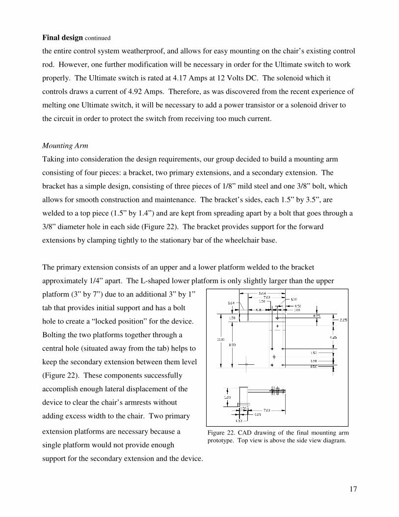
Figure 22. CAD drawing of the final mounting arm prototype. Top view is above the side view diagram.
Final design continued
the entire control system weatherproof, and allows for easy mounting on the chair’s existing control
rod. However, one further modification will be necessary in order for the Ultimate switch to work
properly. The Ultimate switch is rated at 4.17 Amps at 12 Volts DC. The solenoid which it
controls draws a current of 4.92 Amps. Therefore, as was discovered from the recent experience of
melting one Ultimate switch, it will be necessary to add a power transistor or a solenoid driver to
the circuit in order to protect the switch from receiving too much current.
Mounting Arm
Taking into consideration the design requirements, our group decided to build a mounting arm
consisting of four pieces: a bracket, two primary extensions, and a secondary extension. The
bracket has a simple design, consisting of three pieces of 1/8” mild steel and one 3/8” bolt, which
allows for smooth construction and maintenance. The bracket’s sides, each 1.5” by 3.5”, are
welded to a top piece (1.5” by 1.4”) and are kept from spreading apart by a bolt that goes through a
3/8” diameter hole in each side (Figure 22). The bracket provides support for the forward
extensions by clamping tightly to the stationary bar of the wheelchair base.
The primary extension consists of an upper and a lower platform welded to the bracket
approximately 1/4” apart. The L-shaped lower platform is only slightly larger than the upper
platform (3” by 7”) due to an additional 3” by 1”
tab that provides initial support and has a bolt
hole to create a “locked position” for the device.
Bolting the two platforms together through a
central hole (situated away from the tab) helps to
keep the secondary extension between them level
(Figure 22). These components successfully
accomplish enough lateral displacement of the
device to clear the chair’s armrests without
adding excess width to the chair. Two primary
extension platforms are necessary because a
single platform would not provide enough
support for the secondary extension and the device.
18
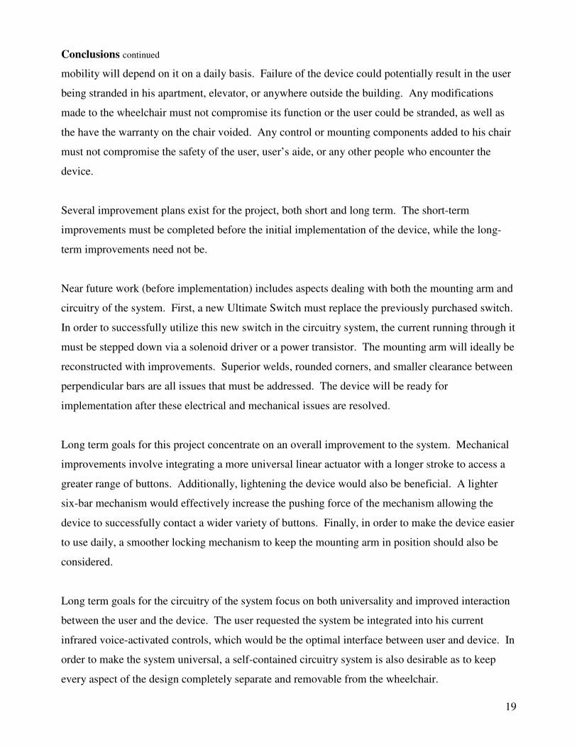
Figure 24. Front view of weatherproof case
demonstrating the role of the rubber O-rings that prevent sideways
movement (white arrows).
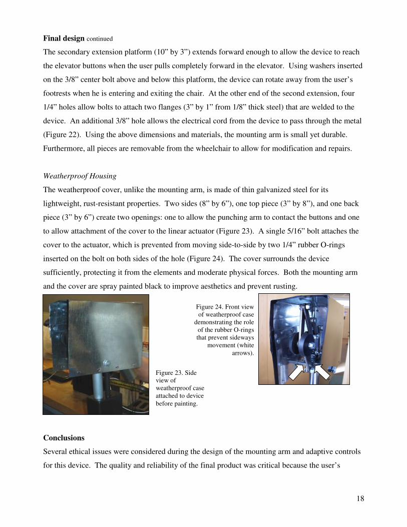
Figure 23. Side view of weatherproof case attached to device before painting.
Final design continued
The secondary extension platform (10” by 3”) extends forward enough to allow the device to reach
the elevator buttons when the user pulls completely forward in the elevator. Using washers inserted
on the 3/8” center bolt above and below this platform, the device can rotate away from the user’s
footrests when he is entering and exiting the chair. At the other end of the second extension, four
1/4” holes allow bolts to attach two flanges (3” by 1” from 1/8” thick steel) that are welded to the
device. An additional 3/8” hole allows the electrical cord from the device to pass through the metal
(Figure 22). Using the above dimensions and materials, the mounting arm is small yet durable.
Furthermore, all pieces are removable from the wheelchair to allow for modification and repairs.
Weatherproof Housing
The weatherproof cover, unlike the mounting arm, is made of thin galvanized steel for its
lightweight, rust-resistant properties. Two sides (8” by 6”), one top piece (3” by 8”), and one back
piece (3” by 6”) create two openings: one to allow the punching arm to contact the buttons and one
to allow attachment of the cover to the linear actuator (Figure 23). A single 5/16” bolt attaches the
cover to the actuator, which is prevented from moving side-to-side by two 1/4” rubber O-rings
inserted on the bolt on both sides of the hole (Figure 24). The cover surrounds the device
sufficiently, protecting it from the elements and moderate physical forces. Both the mounting arm
and the cover are spray painted black to improve aesthetics and prevent rusting.
Conclusions
Several ethical issues were considered during the design of the mounting arm and adaptive controls
for this device. The quality and reliability of the final product was critical because the user’s
19
Conclusions continued
mobility will depend on it on a daily basis. Failure of the device could potentially result in the user
being stranded in his apartment, elevator, or anywhere outside the building. Any modifications
made to the wheelchair must not compromise its function or the user could be stranded, as well as
the have the warranty on the chair voided. Any control or mounting components added to his chair
must not compromise the safety of the user, user’s aide, or any other people who encounter the
device.
Several improvement plans exist for the project, both short and long term. The short-term
improvements must be completed before the initial implementation of the device, while the long-
term improvements need not be.
Near future work (before implementation) includes aspects dealing with both the mounting arm and
circuitry of the system. First, a new Ultimate Switch must replace the previously purchased switch.
In order to successfully utilize this new switch in the circuitry system, the current running through it
must be stepped down via a solenoid driver or a power transistor. The mounting arm will ideally be
reconstructed with improvements. Superior welds, rounded corners, and smaller clearance between
perpendicular bars are all issues that must be addressed. The device will be ready for
implementation after these electrical and mechanical issues are resolved.
Long term goals for this project concentrate on an overall improvement to the system. Mechanical
improvements involve integrating a more universal linear actuator with a longer stroke to access a
greater range of buttons. Additionally, lightening the device would also be beneficial. A lighter
six-bar mechanism would effectively increase the pushing force of the mechanism allowing the
device to successfully contact a wider variety of buttons. Finally, in order to make the device easier
to use daily, a smoother locking mechanism to keep the mounting arm in position should also be
considered.
Long term goals for the circuitry of the system focus on both universality and improved interaction
between the user and the device. The user requested the system be integrated into his current
infrared voice-activated controls, which would be the optimal interface between user and device. In
order to make the system universal, a self-contained circuitry system is also desirable as to keep
every aspect of the design completely separate and removable from the wheelchair.
20
Conclusions continued
In conclusion, the physical modifications to the toggle switch and the electrical modifications of the
Ultimate switch provide a unique, yet simple solution, which allows the user to control the elevator
button pushing device created last spring. In order to mount the device to the user’s chair, a
bracket, along with parallel and perpendicular extensions, were fashioned to attach to the stationary
base of the chair. The combination of adaptive controls and mounting system will increase the
user’s mobility by allowing him to use the elevator to enter and exit his apartment.
References
“Enabling Devices: Online catalog.” 2006. Enabling Devices. 10 Sept 2006. <http://enablingdevices.com>
Karle, S., Lorenz, M., Maslonkowski, E., Matsick, A. “Elevator Controller for Individual with Multiple Sclerosis.” Department of Biomedical Engineering, University of Wisconsin-Madison: May 2006.

21
Appendix A: PDS
ELEVATOR CONTROLLER FOR INDIVIDUAL WITH MULTIPLE SCLEROSIS Product Design Specification
Team Members:
Sara Karle (Co-Team Leader) Ashley Matsick (Co-Team Leader) Michele Lorenz (Communicator)
Alison Boumeester (BSAC) Peter Strohm (BWIG)
Primary Contact:
John O. Fleming, MD Professor, Vice Chair, Neurology Professor, Medical Microbiology and Immunology,
University of Wisconsin Medical School - Department of Neurology, H6/564 CSC Phone: 608-263-5421
Email: [email protected]
Last update: December 12, 2006 Problem Statement/Function:
Our project involves the integration of adaptive controls into a prototype created in the spring of 2006. This device is capable of covering the distance from a wheelchair to an elevator call button, then exerting a horizontal force sufficient to push the call buttons in both the standard elevator car and the corresponding hallway. The controls to be integrated must be operable by stimulus generated by movement no lower than the user’s neck. The device should be attached to the wheelchair in such a way that mobility and other wheelchair functions are not compromised. The final mounted prototype should be protected from physical and environmental damage by a weatherproof enclosure.
Client Requirements: - The device must be attached on the left hand side of the wheelchair - Adaptive controls must allow user to operate device using stimulus generated at the neck or above - Device does not need to be universal with respect to the elevator controls in other buildings - Device and controls must be weatherproof and protected - Width added to the wheelchair cannot hinder maneuverability - Must not obstruct user’s ability to enter and exit the chair
Design Requirements:
1) Physical and Operational Characteristics a) Performance
- Used multiple times daily - Two unique sets of controls (one involving toggle options and the other a momentary contact switch) must move the actuator vertically and engage the solenoid, respectively - Device should not draw an excessive amount of power from the wheelchair battery - Docking of device on chair must not block rotation of chair’s foot rests
b) Safety - Can not alter normal wheelchair or elevator operations - Device must be mounted in such a way that all elevator buttons can be reached - Device controls should not compromise ease of use of current wheelchair controls - Physical components should not endanger nearby people and objects

22
- Entire device should be removable from chair c) Accuracy & Reliability
- Should be able to move to a specific button based on the input of the user - Should provide visual feedback about the position of the pushing component - Sensitivity of controls should allow for at least 90% success when the user attempts to engage the device - Device should not engage without user input - Device should not remain activated if accidental contact of controls occurs
d) Life in Service - 10 years or until upgraded parts are available - Individual parts should be easily serviceable as needed - Each individual part should withstand use multiple times daily - Weatherproof covering and all components of mounting arm must be removable to allow for maintenance
e) Operating Environment - Weatherproof: temperature ranges from 20-90° Fahrenheit, humidity and rain - Must withstand vibrations and dust upheaval caused by wheelchair motion, especially over uneven/bumpy terrain
f) Ergonomics - Should not require physical interaction, with the exception of head/mouth movement - Should not require unnecessary physical stress
g) Size - Total width of chair and device may not exceed 35” and should be significantly less to avoid unnecessary maneuvering by the user - Additional dimensions of device and mounting arm should not cause unnecessary adjustments to normal movement (turning corners, etc.) - Size and location of manual controls should not obstruct vision but should be large enough for easy operation - Components of mounting arm must not interfere with chair’s normal operations (i.e. Rotation of footrests)
h) Weight - Device should not compromise the existing stability of the wheelchair - Controls and housing must not add excessive weight to existing control rod
i) Materials/Aesthetics & Appearance - Exterior materials should be weatherproof - Simple user interface - Uncluttered components
2) Production Characteristics a) Quantity
- One unit needed for individual client b) Target Product Cost
- Minimize overall cost, preferably under $500 3) Miscellaneous
a) Competition - Patent searches returned no similar devices (but components may be individually patented)
b) User Preferences—Control - User prefers device be controlled using preexisting infrared signaling so voice commands can be used, however this possibility may not be feasible

23
Appendix B: Project costs (Fall 2006)
Itemized Materials List for Adaptive Controls
Item Name Quantity Cost
Ultimate Switch 1 $59.95
DPDT Toggle Switch 2 $14.78
Self- Solder Mini 1/8" Phone Jack 1 $4.00
14 gauge wire 36 feet $2.28
Toggle Switch Boot 1 $6.32
Extra Time Epoxy 1 $3.15
Flexible Tubing for Wire 7 feet $5.26
Cable ties 1 pack $2.73
Plastic Tape 1 roll $2.52
1/16" Gasket Rubber 1 pack $2.42
3/8" Copper Straps 1 pack $1.05
Black Spray Paint 1 can $4.18
Plastic Box Body 2 $1.88
Plastic Box Lid 3 $1.55
Total n/a $112.07
Itemized Materials List for Mounting Arm
Item Name Quantity Cost
1/3” x 1 ½” x 4’ Steel Piece 1 $8.43
1/8” x 3” x 3’ Steel Piece 1 $12.65
3" x 6" x 8" Galvanized Steel Box 1 $7.23
Regular Time Epoxy 1 $4.08
¼” Rubber Washers 2 *
3/8” Metal Washers 2 *
5/16” (4” Long) Bolt 1 *
¼” (3” Long) Bolt 1 *
¼” (3/4” Long) Bolts 5 *
3/8” (2” Long) Bolt 1 *
3/8” (2 ½” Long) Bolt 1 *
Small Hardware Total* n/a $14.18*
Total n/a $46.57